Anti-Luddism, Why Arduin Iron
This is a response to the post habrahabr.ru/post/241407 “System for“ Your Game ”” (he did not get into comments) - a scheme for switching on only one of several load channels with the remaining ones blocked by a single click on the corresponding channel button.
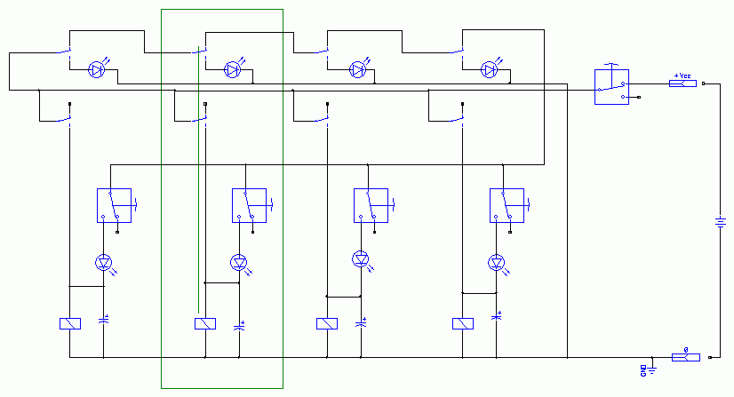
Here is my version of the same, but without a computer with Windows, arduins, and even without a microcontroller. And generally without chips. And even without transistors. The number of channels is unlimited. 5 simple cheap parts per channel.

(I drew a diagram here longer than soldered)
For each channel: relay 1 pc. + button + two [light] diodes. And + a capacitor, if the game is responsible, everything works without them, but sometimes it’s not clear. Buttons are not fixed "clock".
One channel is highlighted by a green rectangle, the simultaneously triggered contacts of one relay in this channel are indicated by a green line between the coil and contacts.
Channels (players) - as many as you like, consumption when waiting - ZERO, the reset button is on the input, it is “on” if it is a toggle switch. It is logical to finish it to the “false start” in a bunch of ways.
We select the supply voltage and the details to each other - I have a “hardware” version with both 12-volt TTI relays and 3.3-volt polar axicom (they have a built-in diode right away - it rings the inductance breaking current).
Description of work:
In standby mode, all relays are off, the diodes are off, the buttons are open, there is no current consumption. When you click on one of the buttons, the corresponding relay is turned on, which turns itself on to power directly, disconnecting its second contact from the power of all the others. Including the “own” button - this is what Conder is for - if the inductive and mechanical inertia of the solenoid and the yoke with contacts are not enough, reconnect the lower contact in the circuit after the upper one is disconnected. Usually enough, but there can be all kinds of relays - therefore, if there is no stable switching on, then add a capacitor, with RC = ~ half a second plus or minus the bast, (R relay and its response time, see datasheet). I stuck at random at 50 microfarads for 3r / pc, thanks to their long legs without wires when mounted.
Everything is soldered right on the feet of the relay, I won’t show the photo, because it looks terribly indecent.
The upper LEDs conditionally show the payload of the main function of the entire circuit, but like the lower ones, it is the diodes that are needed - for the impossibility of the reverse current through the pressed button of one player on the relay of the other, if both were pressed almost simultaneously. The “window of simultaneity” is approximately equal to the response time of the relay — look at the datasheets or measure in fact, for I fed eg. 12-volt relays with 3 finger batteries and they switched significantly longer than from native 12 volts. When pressed simultaneously, priority is obtained for the one on the left of the circuit; simultaneous inclusion of two channels is impossible.
The main disadvantage of the circuit is the large number of connecting wires if the button posts / panels are spatially spaced, and - any failure leads to the inoperability of everything.
Initially, it’s about the same:

The circuit was made for the audio input (or output) selector of some demo stand instead of the furious controller horror issued “up the hill” by a young electronics engineer (either he messed up, or he wasn’t paid and the bookmark worked - but the circuit I couldn’t work without glitches even for a couple of hours and also gave interference in the line). In it, the algorithm is the opposite: “slippers to the last” - each button connected the corresponding channel, disconnecting all the others, and it remained connected while there was power and did not press another button.
And I also have about the same “circuit” immediately on power starters and their buttons - it switches the heating zones in a certain production. Alas, there are no beautiful pictures - just an electric box with starters, wires, buttons.
I suspect that in the pre-electronic era, elevators worked in approximately the same way, and looking at how the adjusters in my house are tormented with a new smart Scherbin elevator, I strongly regret the forced, because of the 30th anniversary, replacing it with our serviceable old one.
This is not an “article”, but only a small illustration of the possibilities of simple circuits on simple details - to implement it, you don’t need a computer, textolite, iron, or a development environment — just pencil paper, a handful of parts and a soldering iron. Well, a couple of hours in transport for inventing. It was written after I saw that electronic students look at it as a quick-release - “I see the buttons, I see the output relays, where is the board with logic?” And although I consider microcontrollers to be a step for humanity comparable to motor motors, sometimes I still want to exclaim: “Gentlemen, do not oversimplify the world in vain!”
- upd:
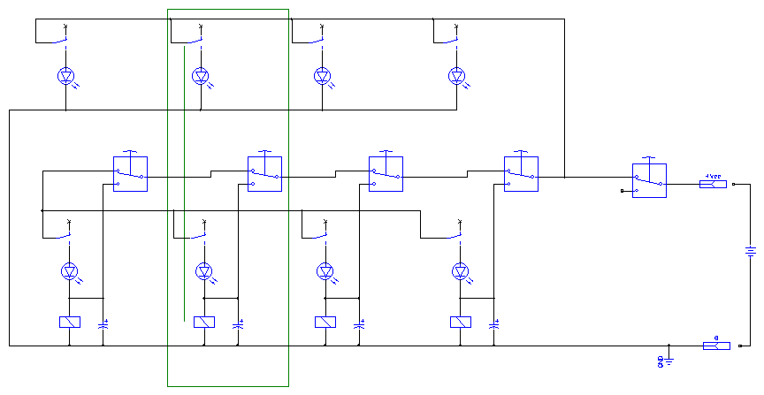
added a more symmetrical and more visual version here from the comment:

- upd2:
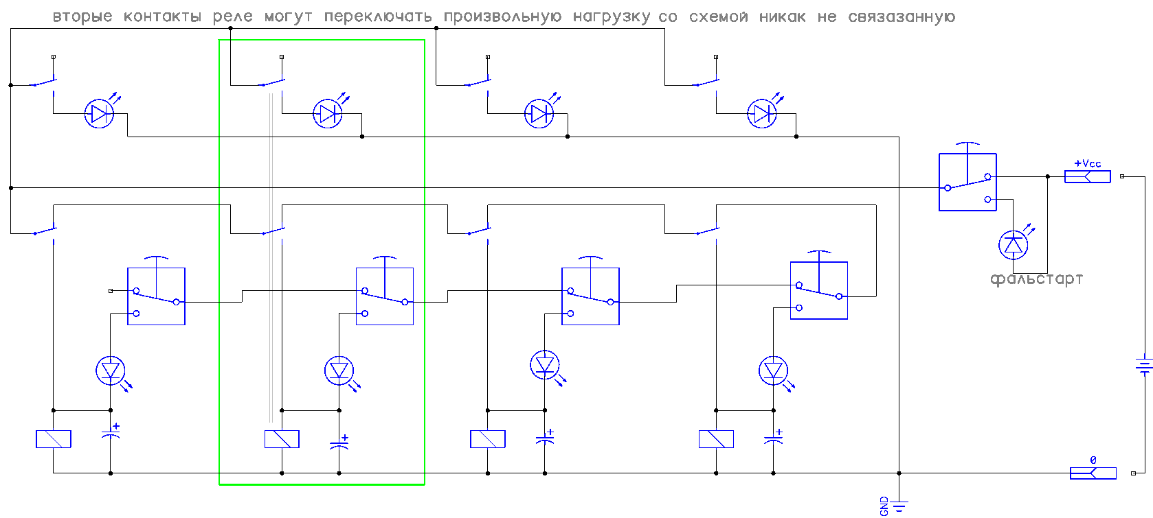
and simplified - here the game is on the fact that the relay usually has a holding current less than the switching current:

Here is my version of the same, but without a computer with Windows, arduins, and even without a microcontroller. And generally without chips. And even without transistors. The number of channels is unlimited. 5 simple cheap parts per channel.

(I drew a diagram here longer than soldered)
For each channel: relay 1 pc. + button + two [light] diodes. And + a capacitor, if the game is responsible, everything works without them, but sometimes it’s not clear. Buttons are not fixed "clock".
One channel is highlighted by a green rectangle, the simultaneously triggered contacts of one relay in this channel are indicated by a green line between the coil and contacts.
Channels (players) - as many as you like, consumption when waiting - ZERO, the reset button is on the input, it is “on” if it is a toggle switch. It is logical to finish it to the “false start” in a bunch of ways.
We select the supply voltage and the details to each other - I have a “hardware” version with both 12-volt TTI relays and 3.3-volt polar axicom (they have a built-in diode right away - it rings the inductance breaking current).
Description of work:
In standby mode, all relays are off, the diodes are off, the buttons are open, there is no current consumption. When you click on one of the buttons, the corresponding relay is turned on, which turns itself on to power directly, disconnecting its second contact from the power of all the others. Including the “own” button - this is what Conder is for - if the inductive and mechanical inertia of the solenoid and the yoke with contacts are not enough, reconnect the lower contact in the circuit after the upper one is disconnected. Usually enough, but there can be all kinds of relays - therefore, if there is no stable switching on, then add a capacitor, with RC = ~ half a second plus or minus the bast, (R relay and its response time, see datasheet). I stuck at random at 50 microfarads for 3r / pc, thanks to their long legs without wires when mounted.
Everything is soldered right on the feet of the relay, I won’t show the photo, because it looks terribly indecent.
The upper LEDs conditionally show the payload of the main function of the entire circuit, but like the lower ones, it is the diodes that are needed - for the impossibility of the reverse current through the pressed button of one player on the relay of the other, if both were pressed almost simultaneously. The “window of simultaneity” is approximately equal to the response time of the relay — look at the datasheets or measure in fact, for I fed eg. 12-volt relays with 3 finger batteries and they switched significantly longer than from native 12 volts. When pressed simultaneously, priority is obtained for the one on the left of the circuit; simultaneous inclusion of two channels is impossible.
The main disadvantage of the circuit is the large number of connecting wires if the button posts / panels are spatially spaced, and - any failure leads to the inoperability of everything.
Initially, it’s about the same:

The circuit was made for the audio input (or output) selector of some demo stand instead of the furious controller horror issued “up the hill” by a young electronics engineer (either he messed up, or he wasn’t paid and the bookmark worked - but the circuit I couldn’t work without glitches even for a couple of hours and also gave interference in the line). In it, the algorithm is the opposite: “slippers to the last” - each button connected the corresponding channel, disconnecting all the others, and it remained connected while there was power and did not press another button.
And I also have about the same “circuit” immediately on power starters and their buttons - it switches the heating zones in a certain production. Alas, there are no beautiful pictures - just an electric box with starters, wires, buttons.
I suspect that in the pre-electronic era, elevators worked in approximately the same way, and looking at how the adjusters in my house are tormented with a new smart Scherbin elevator, I strongly regret the forced, because of the 30th anniversary, replacing it with our serviceable old one.
This is not an “article”, but only a small illustration of the possibilities of simple circuits on simple details - to implement it, you don’t need a computer, textolite, iron, or a development environment — just pencil paper, a handful of parts and a soldering iron. Well, a couple of hours in transport for inventing. It was written after I saw that electronic students look at it as a quick-release - “I see the buttons, I see the output relays, where is the board with logic?” And although I consider microcontrollers to be a step for humanity comparable to motor motors, sometimes I still want to exclaim: “Gentlemen, do not oversimplify the world in vain!”
- upd:
added a more symmetrical and more visual version here from the comment:

- upd2:
and simplified - here the game is on the fact that the relay usually has a holding current less than the switching current:

