Soviet radio stations of the Cold War era
It was the longest war in our history ... But the true history of the Cold War is fraught with many unsolved riddles and secrets: political intrigues, intelligence operations, misleading people and the ambitions of the authorities. The tragedy of mistakes, a monstrous misunderstanding of thoughts of intentions and aspirations of the other side. And the less they knew, the more they hated and feared.

The Cold War is not only an era of tremendous passions, a world confrontation between East and West and the confrontation of the two superpowers, but also an era marked by advanced developments and bold achievements. It was a tough race, covering all areas of life. We touch on one of them - the masterpieces of radio Soviet espionage.
There is an opinion that, strangely enough, agents of the special services of various countries helped to prevent the heating of the "cold war" to a "hot" state. This is what Scouts and Spies. Cold War Agents. ” Zigunenko Stanislav Nikolaevich:
Due to the constant theft of scientific and industrial secrets, leaks of political information, neither side was able to gain a decisive advantage in the global arms race.Not surprisingly, espionage flourished as never before. During this period, from the speech delivered by W. Churchill in Fulton to the fall of the Berlin Wall, many eavesdropping and spy radios and devices were developed. "Hit of sales" - radio stations, spies, agents, army and special forces could not do without them.
Famous spy radio stations of the USSR
Tensor

Spy Radio, 1942
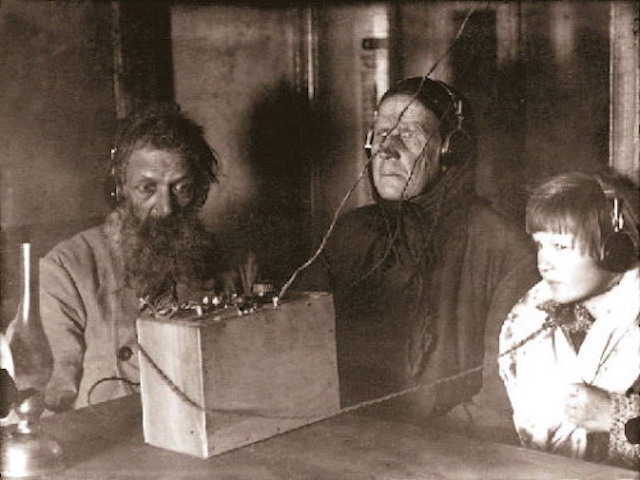
Your radiograms, Comrade Sonia were always shells, were always stronger than shells.Tensor - Tensor / Tenzor - a spy radio receiver, developed and released in the USSR (near Moscow). The device was put into operation in 1942, it was successfully used in the GRU and the NKVD during the Second World War and after it. This is an agent radio station, powered from a network and of high power, was used in cases where there was a need to establish radio communications over long distances (up to 2500 km).
The Tensor kit consisted of four aluminum blocks of the same size: a transmitter, a receiver, a power supply unit (PSU) and a power strip, with the help of cables they connected to one working radio station.
The characteristic of such a radio station:
- frequency range: 3.7 - 14.3 MHz
- transmitter: output power 20-45 W
- receiver: circuit 1-V-1
- weight: 4-7 kg
With the exception of the receiver, all the lamps, knobs of the regulators were located on top of the devices, this not only saved space, but also prevented the transmitter and power supply from overheating. All inscriptions on the cases were in English. Perhaps this was a tactical move to hide the “true nature” of the origin of the device, and some GRU agents were foreigners and did not speak Russian.
During World War II, the kit, lamps, knobs, and spare parts were stored in a canvas bag. Later, during the Cold War, the device was delivered either in a waterproof metal container or in a wooden box.
Tensor Mark 2
The design of all four main blocks of the radio station was thought out to the smallest detail. Each block (17.5 x 10.7 cm) is made in a strong metal frame with rounded corners, the covers on the top and bottom are removable. The cases are two-tone, the handles are made of bakelite or, in the earlier version, aluminum.
Tensor was in production until the end of the 1950s. After World War II, kits were distributed among GRU agents (often in Western Europe). After the Cold War, Tensor radios were discovered in Vienna and its environs (Austria).
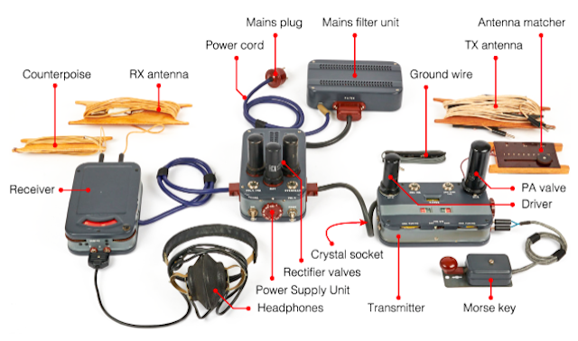
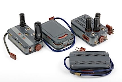
In the above image are four devices of the Tenzor radio station, “accessories”. The line filter was used to transmit voltage to the power supply unit (PSU), a 9-position rotary switch to select the required line voltage (for most Western European countries - 240V).
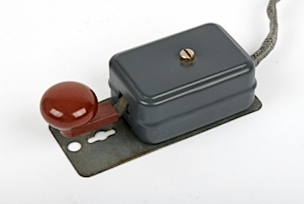
The radio station operated using a telegraph key using the Morse code. A miniature telegraph key (front right) connected directly to the transmitter. Antennas (wired) for the transmitter and receiver provided full-duplex operation of the device.
There were two well-known versions of the Tensor Mark 1 radio station.considered the first version of the kit, and was commissioned in 1942. His power supply unit contained only two 5Z4 radio tubes, a kit with an older version of the telegraph key was supplied. The handle of the voltage switch on the power supply was made of aluminum. Tensor Mark 2 . In the new version (since 1944), the power supply already had three 5Z4 radio tubes, is equipped with a new version of the telegraph key, the details are made of brown or black bakelite.

During the Cold War, the Tenzor radio set was delivered in a wooden box measuring 41 x 28 x 16 cm and weighing about 4.5 kg. Each part of the device was packaged separately, wrapped in greaseproof paper to ensure integrity and safety for a long time. Such a box was hidden in a dry place, such as an attic.
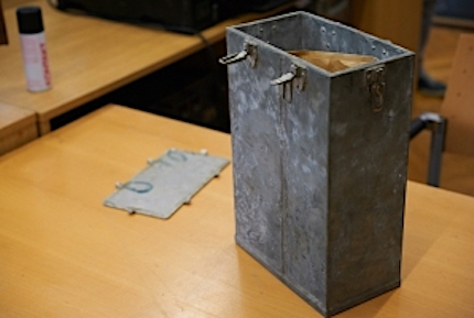
Kits that needed to be hidden in underground caches were usually packed in a sealed metal container, which protected the device from moisture and fungus. The metal container depicted in the photo was accidentally found during road works in the late 1990s (Vienna, Austria). Surprisingly, inside the “in good health” was the Tensor Mark 2 with all the details and instructions in German.
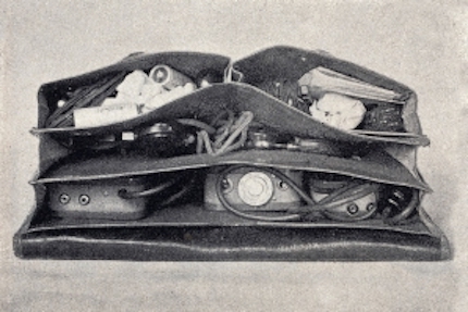
According to German military publications of 1943, the Tenzor radio station was delivered in a canvas bag. Such a bag had several compartments where the device and its spare parts fit safely.
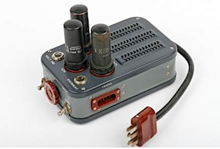
Power Supply

All other devices were connected to the power supply unit (PSU). Through a non-removable cable, voltage came through the line filter. The required voltage was selected using the front rotor, on top of the power supply three radio tubes 5Z4 were honorably seated. There were two output connectors: one for the receiver (left) and one for the transmitter (right).
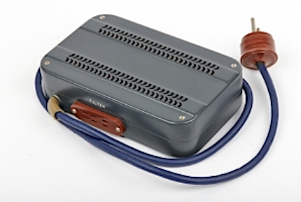
The surge protector is shown in the photo below: a device with a non-removable cable and a power plug, a connector for connecting a power supply. Four electrolytic capacitors and several resistors were used to stabilize the DC voltage, due to their considerable size, the capacitors did not fit inside the power supply, but were installed inside the mains filter.
Radio transmitter

The power cable of the transmitter was connected to the right connector on the power supply, designated as “TRANS”; The Morse telegraph key was connected to the KEY connector, which was on the right. The transmitter was freely adjustable, thanks to the use of a frequency converter, it was possible to select the frequency by installing the appropriate crystal (this is a unique feature of this transmitter, which is not found in other spy radio stations of that era) in the XTAL connector on the left.
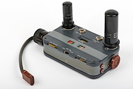
The transmitter was suitable for the frequency range from 3.7 to 14.3 MHz, divided into four bands. The transmitter was with an output power of 13 W or 30 W, this parameter was selected using the switch on the power supply.
Receiver

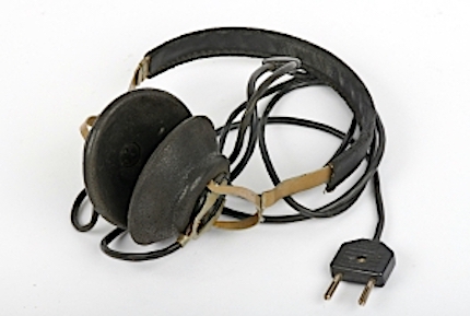
The receiver is housed in a housing that is very similar to the transmitter housing, but its lamps are inside. The receiver power cable is connected to the left connector on the “REC” power supply, the antenna is connected to the terminals at the rear, and the headphones are connected to the front.
A receiver with a (free) frequency selection mode: you can safely adjust the frequency in the range 3.3 - 15 MHz and tune to the desired one using two gear wheels on the sides of the device. Front left was the volume control. A telegraph key for transmitting Morse code characters was connected to the transmitter through two banana-type connectors.
Below in the photo are headphones made by the USSR that came with the Tensor radio station. Although there were other options for headphones.
The kit included wire antennas that were wound on a wooden base. Separate antennas and balances were provided for the transmitter and receiver to provide full duplex operation (i.e., without switching the antenna between the transmitter and receiver).


Antenna matching device The
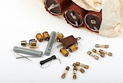
kit was equipped with a set of spare parts for repair in the field: spare valves, resistors, capacitors, bulbs, fuses.
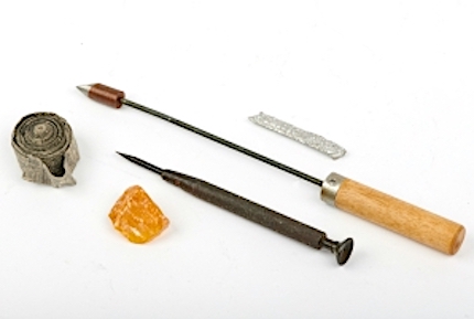
And what about tools without the same field repair: a soldering iron with a wooden handle, a piece of resin, a screwdriver and insulation tape.
The set included the instruction manual for the devices, as well as a personal set of tables and instructions for the agent, to get in touch with the Center. In the tables - detailed information in the form of graphs regarding the transmission / reception of messages, a certain time, day, week and month, frequency, call signs, etc. are indicated. Such tables were not only in printed form, but
also imprinted on film, which allowed, if necessary, to hide or reproduce information.

Communication program of the correspondent with the Center

Table of the report on the working hours of the correspondent (days of the week and day of the month)
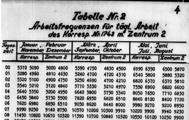
Table on the working frequency for contacting a specific correspondent
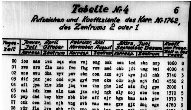
Call signs
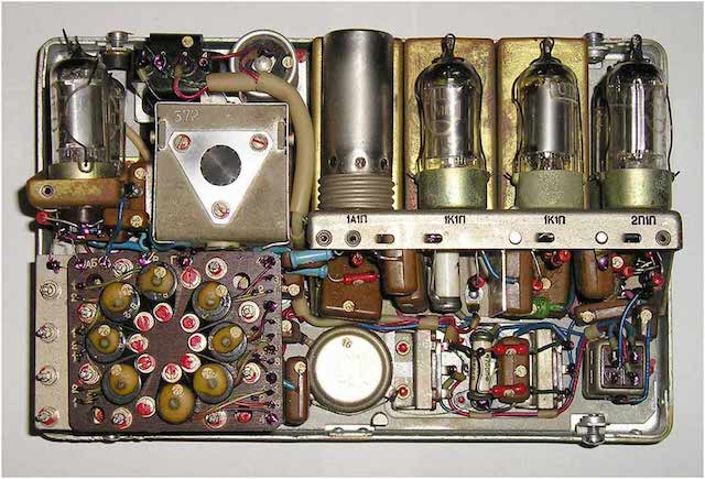
Each block filling
The transmitter was housed in a metal case, its dimensions are 17.5 x 10.5 x 4.8 cm (lamps do not count), weighing about 1100 grams (with lamps), the upper and lower case covers are removable. When the top cover was removed, the “interior” of the transmitter opened to the eyes: two frequency scales (each with four ranges), a channel selector, two indicator lamps and two lamp sockets. Circuits and passive elements are visible if you turn the device over and remove the second cover.

The receiver with dimensions of 17.5 x 10.5 x 4.7 cm and weighing about 936 grams was dressed in a metal case. Also had two removable covers. The frequency dial occupied most of the receiver, in fact it is a large wheel painted in two colors - blue and red (for different ranges).

Receiver
Metal power supply housingidentical to the transmitter and receiver cases in width and length, but it is slightly higher due to the AC transformer located in it. Half of the free space inside was occupied by a network transformer, in the other part there were three sockets for radio tubes, a power selector, indicator lamps and passive components. A feature of the power supply can be safely considered the absence of any capacitors to stabilize the DC voltage. These capacitors were located inside the mains filter, which is connected to the power supply and the outlet.

Power supply
The link between the mains and the power supply unit (PSU) - surge protector- the same dimensions as the transmitter and receiver, weighing 765 grams. Although it comes in a separate case, it is actually an integral part of the power supply, it contains electrolytic capacitors (several resistors) necessary to stabilize the DC voltage.

Line filter
The line filter is connected to the power supply via a 6-pin connector. At the time the tensor device was created, the life cycle of electrolytic capacitors was little known. Therefore, a spare set of capacitors was always present in the kit, so that in case of anything, the operator could carry out field repairs using his hands and a soldering iron. All four electrolytic capacitors with a capacity of 20µF.
Specifications

Transmitter:
- Power 13-30W (CW only)
- Frequency 3.7 - 14.3 MHz
- 4 Ranges
- Lamps 6F6, 6L6
- Size 17.5 x 10.5 x 4.6 cm (without lamps)
- Weight 1000 grams (1106 grams with lamps)
Ranges:
- Red 3.7 - 5.2 MHz
- Black 5.2 - 7.2 MHz
- Green 7.2 - 10.2 MHz
- Yellow 10.2 - 14.3 MHz
Receiver:
- Frequency 3.3 - 15 MHz
- 2 ranges
- 3 lamps 6J7
- Dimensions 17.5 x 10.5 x 4.6 cm (without lamps)
- Weight 639 grams
Power Supply:
- Could be powered by AC 90, 100, 110, 125, 140, 180, 200, 220 and 240 V
- Dimensions 17.5 x 10.5 x 6.1 cm (without lamps)
- Weight 3080 grams (with lamps)
Network filter
- Dimensions 17.5 x 10.5 x 4.5 cm
- Weight 765 g
Lamps:
Spare parts:
- 3 x Electrolytic Capacitors 20µF
- 5 x bulbs 2V / 75mA, E10
- 1 x Neon lamp
- 2 x 100 kΩ / 2 W resistors
- 1 x 1 kΩ / 1 W resistor
- 1 x Capacitor
- 4 x 1A fuse
- 4 x 2A fuse
PR-56

PR-56 or PR-56A agent portable HF receiver, used by agents of the KGB or GRU, began to be produced in 1956 (USSR). PR-56A was used in a special short-wave transmit-receive portable telegraph radio station RION. Such a radio station was designed for simplex and half-duplex two-way communication.
The dimensions of the receiver are 20.5 x 13 x 8 cm, its body is made in gray metal. Initially, the device was given the code name PR-56, after the improvement of the PR-56A. This is a superheterodyne receiver (the main amplification is carried out at an intermediate frequency), the sensitivity is 2.0 - 5.5 μV.
All PR-56 controls are located on top of the receiver. In the lower left corner is a 4-pin power connector, a little further, on the right - a headphone jack (4400 Ohms). And the interaction with the receiver was quite simple, and the build quality of the device was perfect.
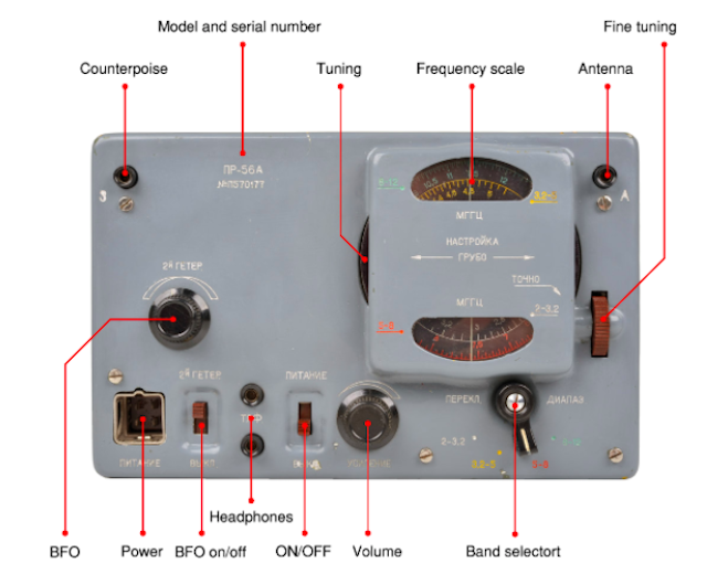
PR-56A covered the frequency range of 2-12 MHz, divided into four bands (highlighted in different colors):
- 2 - 3.2 MHz (white)
- 3.2 - 5 MHz (yellow)
- 5 - 8 MHz (red)
- 8 - 12 MHz (green)
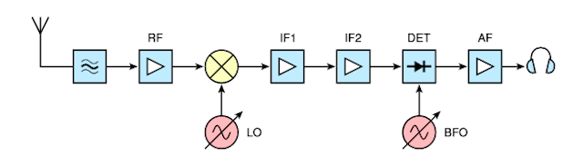
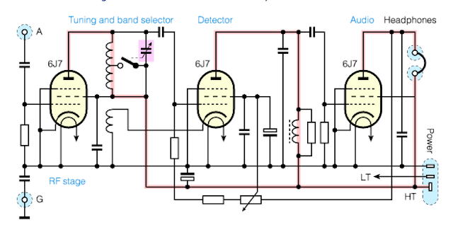
Receiver block diagram
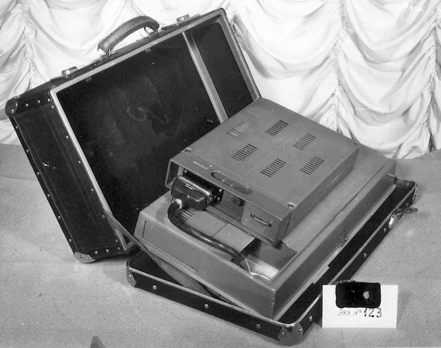
Radio station "RION"
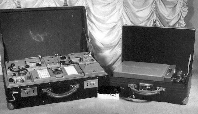
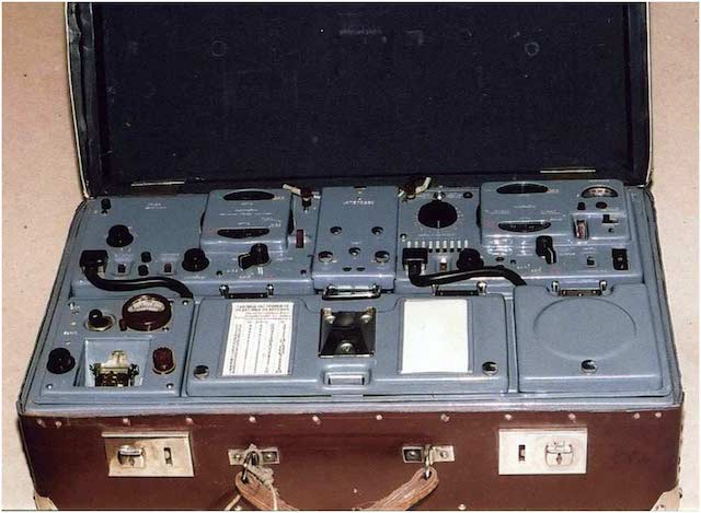
The special shortwave transceiver portable telegraph radio station `` RION '' was intended for simplex and half-duplex two-way communication. The spy device was intended for clandestine operations in foreign countries and, as a rule, went in a brown suitcase made of fiberboard, worked in the frequency range from 2.5 to 10 MHz (transmitter) and from 2 to 12 MHz (receiver PR-56). The station consisted of a PR-56A receiver, a RION transmitter, and a power supply; the remaining space in the suitcase was reserved for spare parts and cable storage.
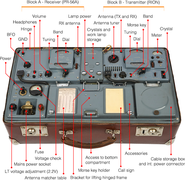
The RION radio station consisted of a PR-56 type receiver, a RION type transmitter, a cassette with a set of dry batteries, a vibration transducer, a rectifier, a receiver antenna (10 m) and a transmitter (18 m), a transmitter counterweight (15 m) with solders, a miniature telegraph key, spare lamps, backup transmitter cable, connection cables, spare vibrator. All this stuff fit in two suitcases. An inverter was placed in a smaller case for converting direct current to alternating current. Thus, the device could be powered in the field, for example, from a 12 volt battery with a capacity of at least 45 ampere-hours. The maximum voltage that can be applied to the vibration transducer is 13 volts; the minimum is 9 volts.
A set of dry batteries provided the station with normal operation for 4 sessions lasting 30 minutes each.
The RION radio station cannot be called light, in total its weight was 37 kg, such a device could work under extreme conditions, the operating temperature range was from -40 ° C to + 50 ° C (provided that there were no sudden temperature changes), 85% relative humidity was allowed at + 25 ° C.
The receiver in the RION radio station was the one previously considered in Article PR-56 or PR-56A. It was developed a year earlier than the RION station itself (1956), in addition, it was supplied separately and could be used in other spy radio stations. Initially, the PR-56 had a 3-digit serial number, but for the RION station, the serial number is indicated in the “P570xxx” format.
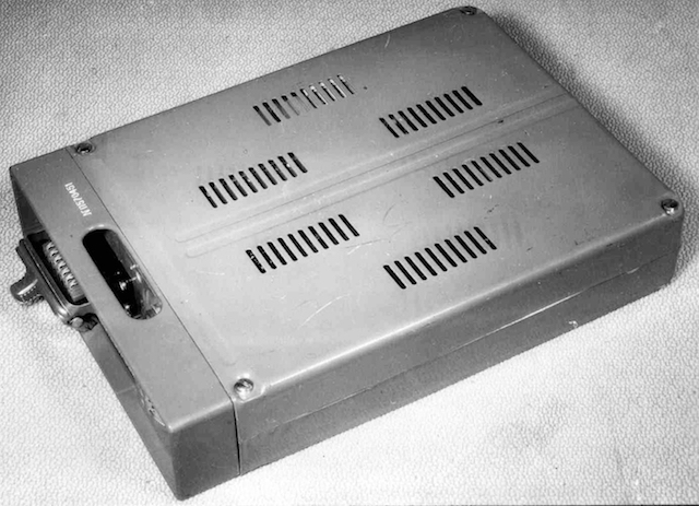
Power Supply
The RION-P-57 transmitter with a serial number in the P570xxx format was specially designed for the RION radio station and, unlike the receiver, was not used as a component of another station. He worked in the frequency range from 2.5 to 10 MHz, divided into four partial sub-bands - 2.5-3.5 MHz, 3.5-5 MHz, 5-7 MHz and 7-10 MHz, respectively. The transmitter could provide operation both in quartz stabilization mode and in self-excitation mode in the entire frequency range. The master oscillator is the main part in the transmitter circuit; it was made according to the Schönbel scheme on a 4PIL lamp; the oscillation frequency of the master oscillator was provided with a high stability by the reliable mounting of parts, the use of special heat-compensating capacitors in the master oscillator circuits.

Inverter
The service life of the RION radio station was 1000 communication sessions, each lasting no more than 2 hours. The device should have been stored in rooms with temperatures from +10 ° C to +40 ° C with an air humidity of not more than 75%. When transporting RION over long distances, all the blocks were installed in their places and fixed, the suitcases were securely closed. If the “trip” took more than 10 days, the battery pack went separately packaged.
The following articles will touch upon the equally amazing radio stations of the Cold War era developed in the USSR.
Thank you for staying with us. Do you like our articles? Want to see more interesting materials? Support us by placing an order or recommending to your friends,30% discount for Habr users on a unique analogue of entry-level servers that was invented by us for you: The whole truth about VPS (KVM) E5-2650 v4 (6 Cores) 10GB DDR4 240GB SSD 1Gbps from $ 20 or how to divide the server correctly? (options are available with RAID1 and RAID10, up to 24 cores and up to 40GB DDR4).
Dell R730xd 2 times cheaper? Only we have 2 x Intel Dodeca-Core Xeon E5-2650v4 128GB DDR4 6x480GB SSD 1Gbps 100 TV from $ 249 in the Netherlands and the USA! Read about How to Build Infrastructure Bldg. class using Dell R730xd E5-2650 v4 servers costing 9,000 euros for a penny?