We defeat the CAN bus. Part 1. Technology

Today I want to introduce you to the interesting CANNY microcontroller platform . This is an overview article in which you will learn about technology, and in subsequent articles I will tell you about working with CAN messages, CANNY integration with Arduino Mega Server, and about the possibilities that this bundle provides.
Why canny From the name of the CAN bus, which is widely used in transport and, in particular, in all modern cars as an on-board network. So, what can be done with a specialized controller connected to the CAN bus of your car?
CAN bus
Figuratively speaking, the CAN bus is the nervous system of your car. It transmits all the information about the state of the units and systems, as well as control commands, which largely determine the behavior of the car. Ignition of headlights, opening and closing doors, control of music playing in the car interior, alarm operation, etc. - all this works and is controlled by this bus.
Physically, the CAN bus is two twisted wires and is very easy to install and connect. Despite its simplicity, it, thanks to its differential nature, is well protected from various interference and interference. High reliability and a large permissible network length, up to 1000 meters, helped CAN to gain wide popularity among manufacturers of various, not only automotive equipment.
CANNY controllers
This is a whole family of specialized controllers that have built-in "native" support for working with the CAN bus. This applies to both the "iron" part, and support at the level of "software".
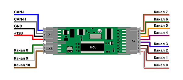
The flagship of the line is the CANNY 7 controller, the most powerful and having maximum capabilities. A large amount of memory, powerful outputs that allow you to directly control the car's relay, an intelligent short-circuit protection system, protection against inrush currents and voltage in the vehicle's on-board network - all this makes this controller an excellent solution for implementing any of your ideas and projects.
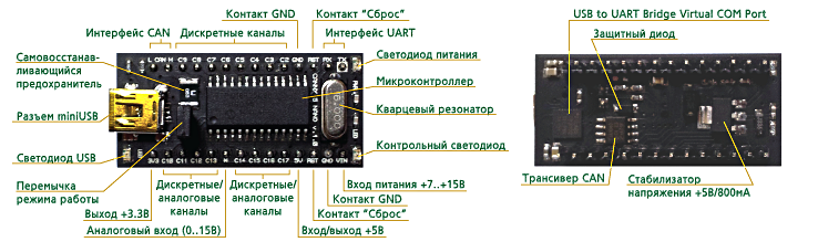
In addition to CANNY 7, there are several more models in the controller line, we will conduct our experiments with a simpler built-in model CANNY 5 Nano. It also supports working with the CAN bus, but at the same time it is similar to the familiar Arduino Nano.
Visual programming

The developed CAN bus support is not the only feature of these controllers, besides CANNY have their own programming environment, CannyLab, but not “normal”, but visual, where the whole process of writing programs comes down to manipulating the finished structural blocks, setting their parameters and connecting inputs and the outputs of these blocks in a certain sequence, in accordance with the algorithm of the problem being solved.
Not a single line of code!
Is this good or bad? In my opinion, this is a matter of habit. As a person accustomed to “traditional” programming, it was unusual for me to manipulate blocks instead of writing lines of code. On the other hand, there are many adherents of just such an approach to compiling algorithms, and it is believed that for engineers and "non-programmers" this is the most simple and affordable method of programming microcontrollers.
At least I was "fun" to make programs in this way and after a while I even began to like it. It is possible that if you continue to do this, then after a while writing the code will seem uncomfortable.
CannyLab is a free development environment and you can free download it from the developers site, it also does not require a special installation procedure - just unzip the archive file - and you can start working.
Connection
Connecting a CANNY 5 Nano to a computer is not much different from connecting Arduino controllers. If there is a Silicon Labs CP210x driver in the system, or after installing it from the downloaded CannyLab distribution, Windows creates a virtual COM port and CANNY is ready to work. In my case, it was still necessary to restart the computer, but perhaps this is a feature of my system.
Practical examples
Let's look at simple examples of how to perform actions familiar to us in the Arduino IDE in CannyLab. Let's start with the traditional LED flashing.
In the CANNY 5 controller, on the C4 pin (Channel 4) there is a test LED (analogue of the LED located on the 13th pin in Arduino). And it can also be used for indication and experiments, which we will use.
What does it take to blink an LED in the CANNY controller? There are only two things you need to do - configure the fourth channel pin as an output and apply a signal from the PWM generator to this output. We have done all these actions more than once in the Arduino IDE, let's see how it looks in CannyLab.
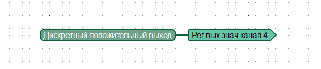
So, configure the fourth channel pin as an output
We configure the PWM generator. We set a period of 500 milliseconds, filling - 250 milliseconds (that is, 50%) and 1 (true) at the input of the Start generator and ... that's it! You do not need to do anything else - the program is ready, it remains only to fill it into the controller.

Simulation mode
Here a few words should be said about the process of simulation of the controller’s work on the computer and the filling of the developed program into the memory of the “iron” controller.

The CannyLab development environment allows you to run and debug a program without writing it to the controller's memory. In simulation mode, you can see the result of the program directly in real time and even intervene in its work.
Pouring into the controller
For the CANNY controllers to work, before filling in the program (in the terminology of the “diagram” developers), you first need to fill in the operating system “Device / System Software / Write”. This needs to be done only once, for this you need to select the file with the extension .ccx corresponding to your controller .
After the program is written and debugged, it can be downloaded to your controller. This is done simply - in the menu, select the item "Device / Chart / Record" and after a few seconds the program is written to the controller.
Next, you need to disconnect the controller from the computer’s USB port, remove the jumper on the board, and you can turn on the programmed controller, which after turning on will work according to your program.
Analog inputs
In order to better understand the principle of programming CANNY controllers in the CannyLab development environment, let's look at an example of working with the analog input in this system.
We will monitor the voltage level on the 10th pin of the controller and if it is in the range of 2.5 V ± 20%, we will light the LED built into the board.
As in the previous example, we configure the 4th pin as an output in order to be able to control the operation of the LED.

Turn on the ADC on channel 10.

Next, we use two logic blocks that give 1 to the output if the voltage is in a given range. The full range is from 0 to 4095.
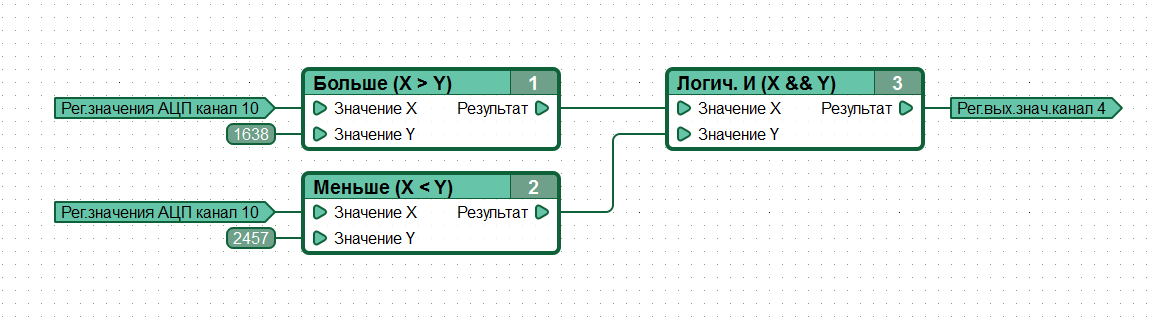
The “Logical AND” block completes the work and from its output controls the operation of the LED on the board.
That's all. What we used to do on Arduino, we easily did at CannyLab. It remains only to get comfortable in this programming environment and you can easily and naturally create your own projects on this platform.
These simple programming examples are provided so that you can understand the principle of visual programming of CANNY microcontrollers. In future work you will be helped by excellent reference documentation and developer support on the site and the system forum.
Conclusion on the introductory article of the cycle
By connecting a CANNY controller to your car, you can realize many interesting and unique ideas, for example, non-standard alarms that are not so easy to open (due to their non-standard nature) or add new functions that you dreamed about, but did not hope that it was possible to implement on practice.
If you like CannyLab-style visual programming, then CANNY controllers can be an interesting alternative to Arduino for you or work in conjunction with Arduino controllers. We will talk about this in the second article of the series, in which I will tell you about the integration of CANNY controllers with the Arduino Mega Server system .
Let me remind you that AMS now works not only on Arduino boards, but also on ESP8266 wireless Wi-Fi modules, and it will be a talk about such a bundle next time.
And as usual, stay with us, it will be interesting!