January 25, 2016 at 14:03
What's inside the "Air Quality Monitor" (analysis and analysis)
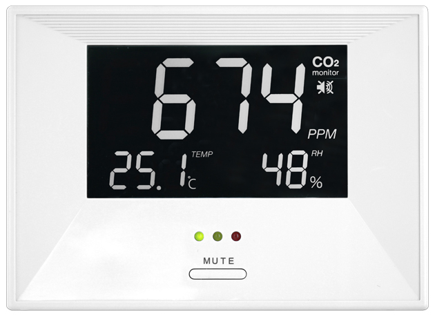
Having read a few days ago on Geektimes about the CO2 monitor from dadget , I could not pass by such an unusual device. I bought it for the intended use “here and now”, as I was concerned about the air quality in the apartment, but with an eye to integrate it into the “smart home” system in the future. That's about the last speech in the post and it will go.
I want to warn you right away that under the cut will be only photos and my assumptions, unfortunately I have no opportunity to check everything in practice.
upd:
added, not caught due to criminal negligence, general photos.
also added bonus video of the CO2 sensor
A small preliminary summary of the information that I collected before I decided to disassemble the device. Of course, Dadget did not develop this device themselves. Real manufacturer: Zyaura . On their website it is indicated that there are two modifications - ZG1683R and ZG1683RU - the latter has the ability to connect to a computer via USB to take readings. Since when connecting to a PC, my device is not defined as a device and does not interact with a computer in any way, I concluded that this is most likely the ZG1683R.
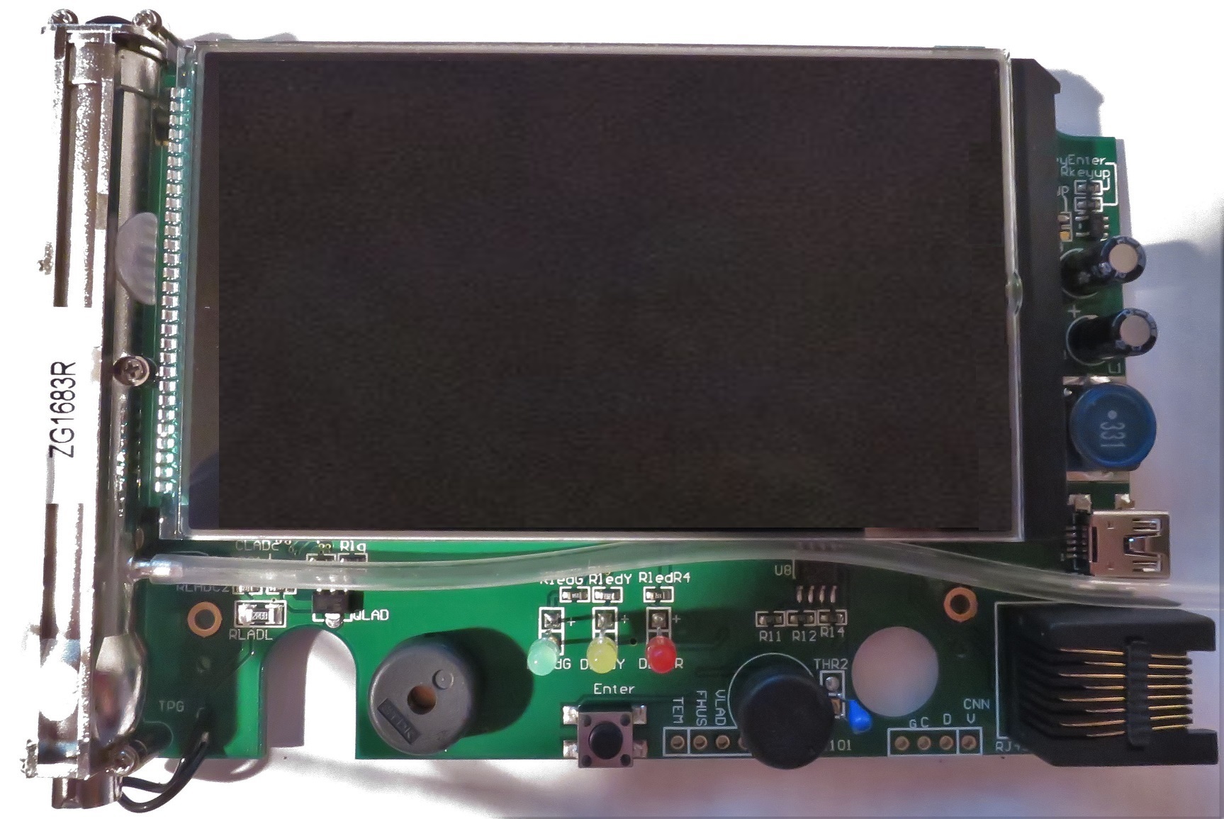
The device is disassembled by unscrewing 3 screws on the back side. Then you just need to overcome the plastic latches around the perimeter. The first thing that catches your eye: behind the plug on the case was the RJ45 connector.

The device board is well signed, for example, next to the humidity sensor, its model is indicated - this is HS1101. Unfortunately, I could not find any inscriptions on the sensor itself, but if it is really HS1101, then it seems very strange that the humidity range of the device is limited to 20% -90%, since the sensor itself can measure from 1% -99% by datasheet. The oddity of chopping off the range up to 20% is that in the winter time in the apartment, if the owner has not bothered with additional moisture, the device will always show “Lo” instead of humidity.
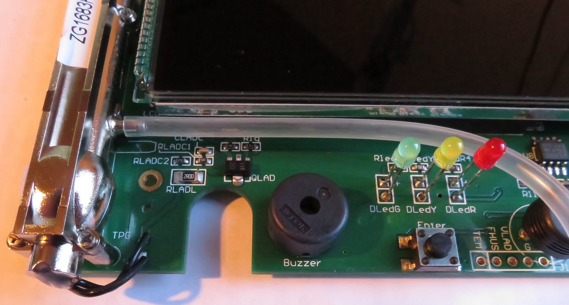
Go to USB. It can be seen that the data ± tracks from the connector go somewhere deep into the screen. Unfortunately, I did not dare to solder a huge number of screen legs to look under it, being afraid of damaging an expensive device due to its curvature. I could not determine where exactly the tracks go, but under the screen you can see the footprint under the microcircuit.

I can assume that the tracks go to it, and then you can say goodbye to USB data collection, or, as another option, they can go to some other chip, and USB data exchange is turned off by software or hardware - this is a more optimistic option .
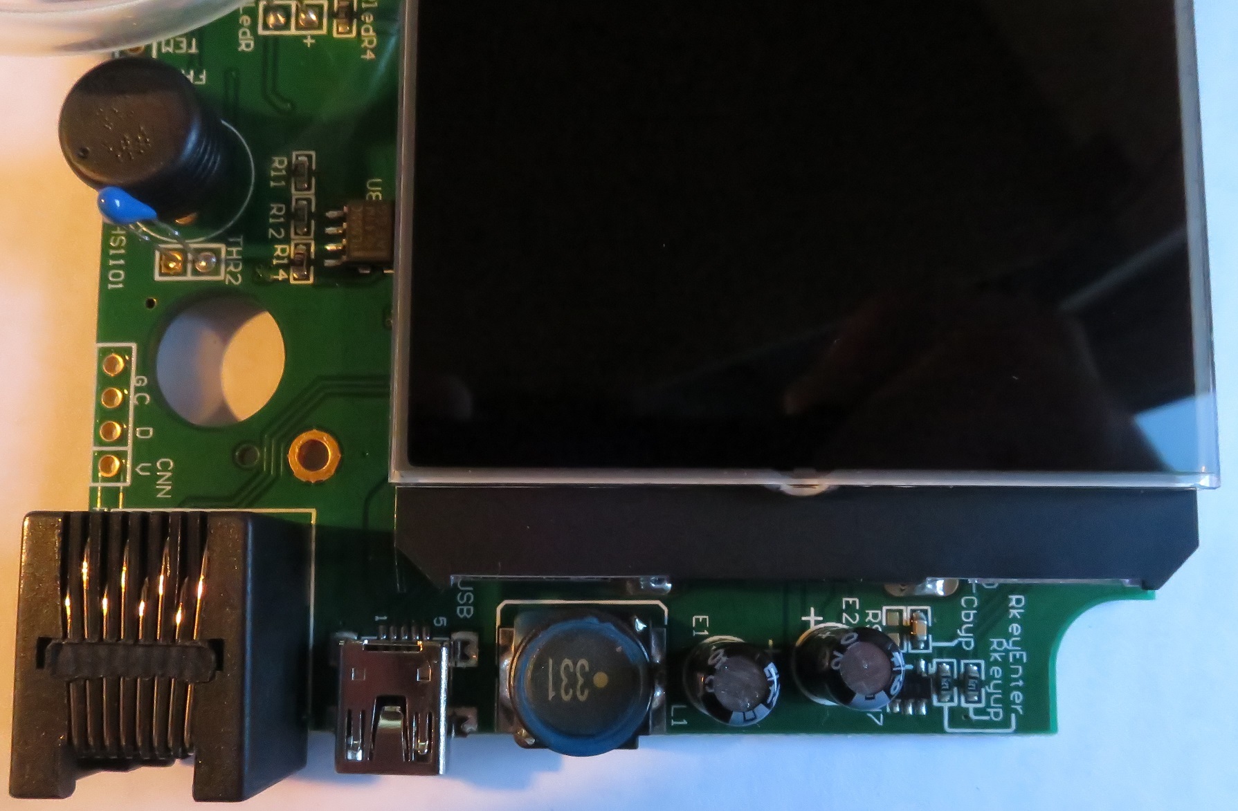
The next thing I noticed was 4 sets of diagnostic contacts, separated at the edges of the board.
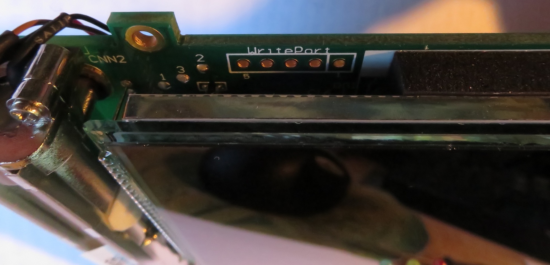
The first is located behind the screen on the left and signed by WritePortUnfortunately, I do not know what it is for.
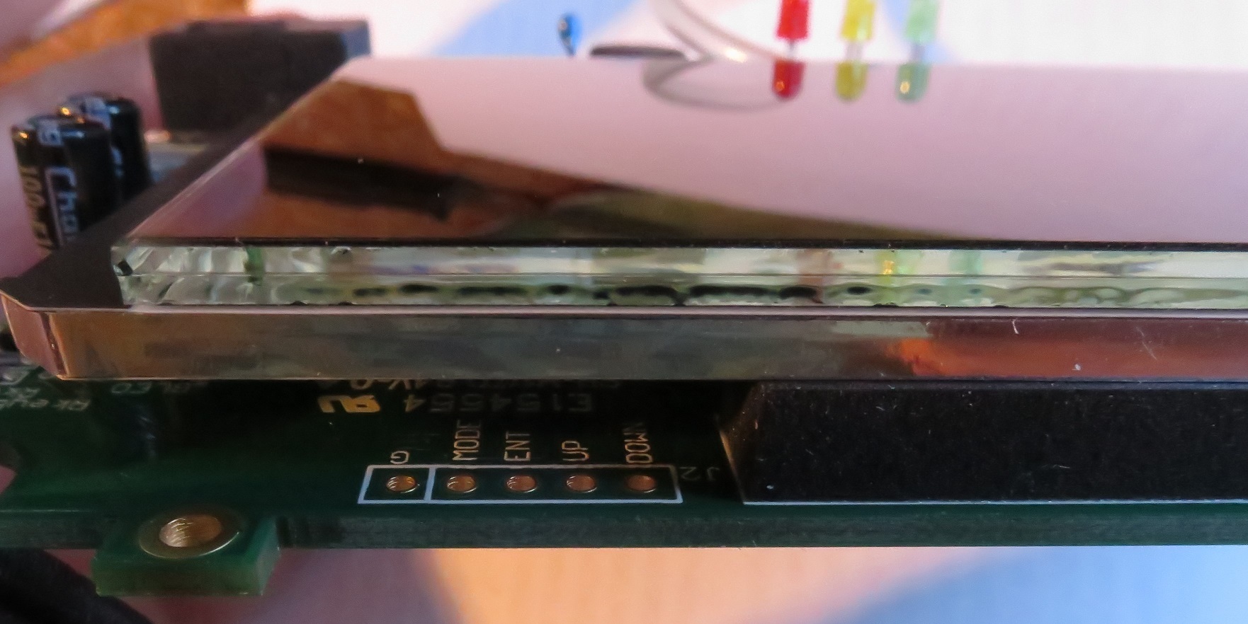
The second is located at the top right, the pins are signed as down , up , ent , mode . Google says they are used to calibrate the CO2 sensor.
At the bottom left, the pins are signed as tem fhus vlad rfc and G , Google did not suggest anything meaningful, tem - definitely the temperature, the rest is unknown.
upd: in the comments, vanxant suggested that fhus is a frequency humidity sensor
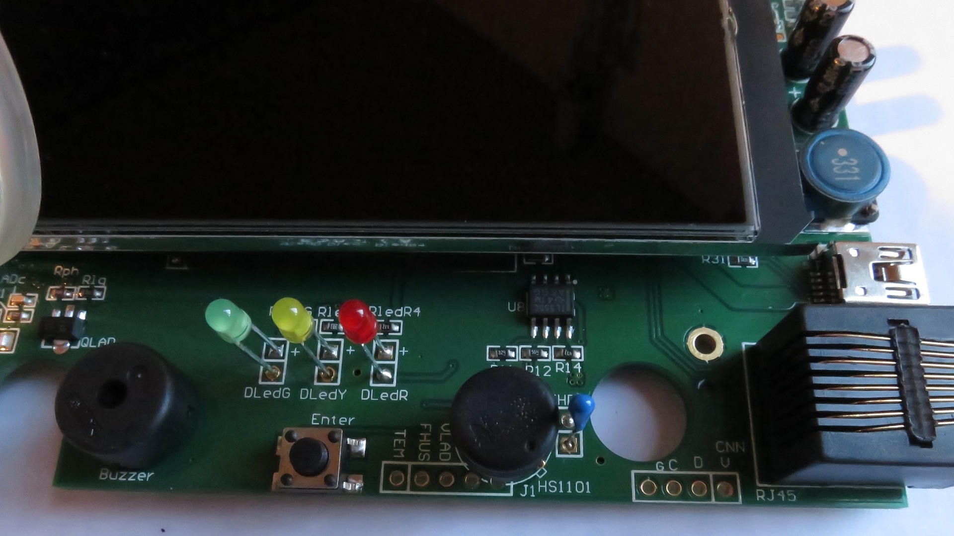
Well, finally, the contacts on the RJ45 are duplicated at the bottom right. They turned out to be the most useful in my study. I came across a pagewhere the Zyaura device was described with the same RJ45 port and similar G, C, D, V contacts.
There was also posted a sketch for Arduino, which allows reading sensor information from them.
To summarize:
“Air Quality Monitor” turned out to be more useful than it looks at first glance. Obviously, it can be used in a smart home system to monitor CO2 levels and more. I hope that the post will answer the questions of those who doubted whether it is worth starting their practical experiments.
UPD:
general photos were added, a photo of an unsoldered chip under the screen,
while still turning on the device in a disassembled state, I shot a video of the CO2 sensor
I want to warn you right away that under the cut will be only photos and my assumptions, unfortunately I have no opportunity to check everything in practice.
upd:
added, not caught due to criminal negligence, general photos.
also added bonus video of the CO2 sensor
A small preliminary summary of the information that I collected before I decided to disassemble the device. Of course, Dadget did not develop this device themselves. Real manufacturer: Zyaura . On their website it is indicated that there are two modifications - ZG1683R and ZG1683RU - the latter has the ability to connect to a computer via USB to take readings. Since when connecting to a PC, my device is not defined as a device and does not interact with a computer in any way, I concluded that this is most likely the ZG1683R.
The device is disassembled by unscrewing 3 screws on the back side. Then you just need to overcome the plastic latches around the perimeter. The first thing that catches your eye: behind the plug on the case was the RJ45 connector.
The device board is well signed, for example, next to the humidity sensor, its model is indicated - this is HS1101. Unfortunately, I could not find any inscriptions on the sensor itself, but if it is really HS1101, then it seems very strange that the humidity range of the device is limited to 20% -90%, since the sensor itself can measure from 1% -99% by datasheet. The oddity of chopping off the range up to 20% is that in the winter time in the apartment, if the owner has not bothered with additional moisture, the device will always show “Lo” instead of humidity.
Go to USB. It can be seen that the data ± tracks from the connector go somewhere deep into the screen. Unfortunately, I did not dare to solder a huge number of screen legs to look under it, being afraid of damaging an expensive device due to its curvature. I could not determine where exactly the tracks go, but under the screen you can see the footprint under the microcircuit.
I can assume that the tracks go to it, and then you can say goodbye to USB data collection, or, as another option, they can go to some other chip, and USB data exchange is turned off by software or hardware - this is a more optimistic option .
The next thing I noticed was 4 sets of diagnostic contacts, separated at the edges of the board.
The first is located behind the screen on the left and signed by WritePortUnfortunately, I do not know what it is for.
The second is located at the top right, the pins are signed as down , up , ent , mode . Google says they are used to calibrate the CO2 sensor.
At the bottom left, the pins are signed as tem fhus vlad rfc and G , Google did not suggest anything meaningful, tem - definitely the temperature, the rest is unknown.
upd: in the comments, vanxant suggested that fhus is a frequency humidity sensor
Well, finally, the contacts on the RJ45 are duplicated at the bottom right. They turned out to be the most useful in my study. I came across a pagewhere the Zyaura device was described with the same RJ45 port and similar G, C, D, V contacts.
There was also posted a sketch for Arduino, which allows reading sensor information from them.
To summarize:
“Air Quality Monitor” turned out to be more useful than it looks at first glance. Obviously, it can be used in a smart home system to monitor CO2 levels and more. I hope that the post will answer the questions of those who doubted whether it is worth starting their practical experiments.
UPD:
general photos were added, a photo of an unsoldered chip under the screen,
while still turning on the device in a disassembled state, I shot a video of the CO2 sensor