Making an “eternal” mass air flow sensor on ATiny13
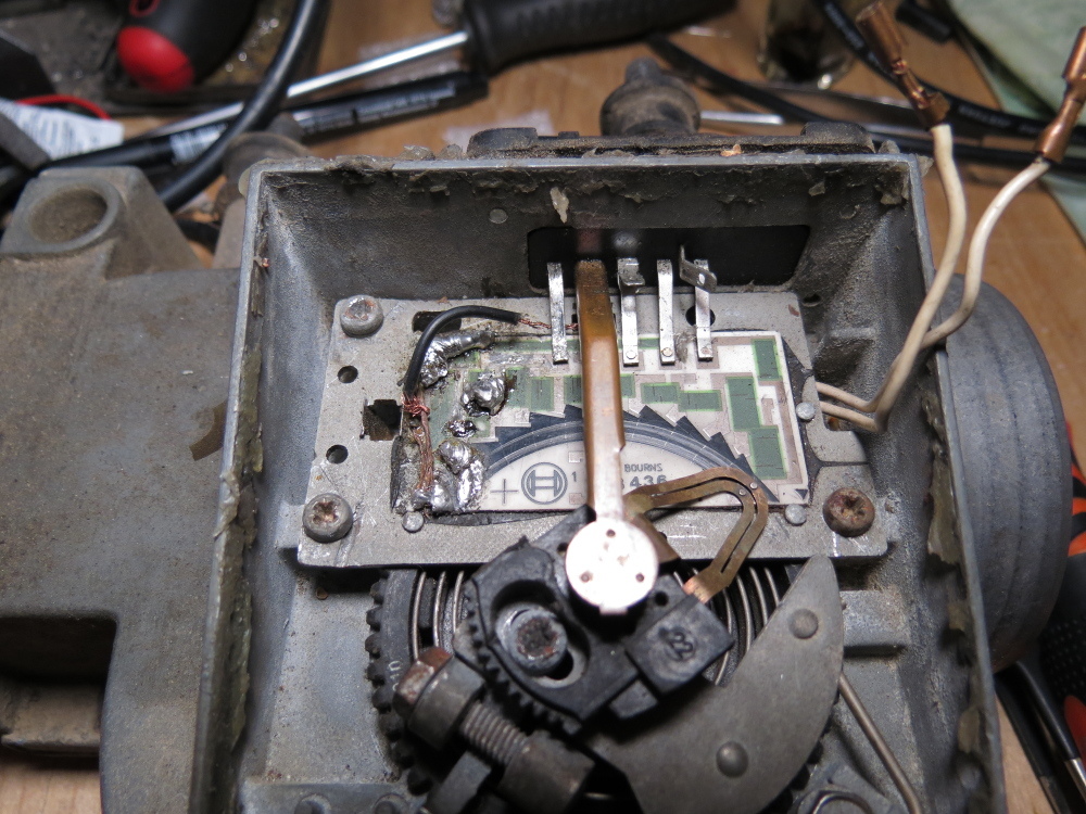
This project appeared because of the reluctance to buy a part that was in use for about 30 (thirty) years for a rather rather large amount of 3,000 - 5,000 rubles. We can say that this will be a test of the pen in circuitry and microcontroller programming. If interested - continued under the cut.
Caution a lot of photos!
So, we begin to support bicycles with crutches.
Input data
BMW E30 coupe in 1986 with M10B18 engine (4 cylinders, 1.8L, injector):

Problems
1. Sneezes
2. Does not travel
3. Eats and does not get fat.
Years in Russia did not spare her. High-quality gasoline, salt baths, “porous roads” . However, most of all she got from the former owners and the harsh Russian auto mechanics, meaningless and merciless, who made repairs of dubious necessity and effectiveness. A vivid example of one of these repairs, you can admire the KDPV. And what is it so little white, all in solder? This is a ceramic board - the main part of the DMRV , film resistors are applied to it and a path along which a movable contact should run. As you can see in the photo, she cracked, and someone tried to restore it in such a barbaric way. To no avail. Here it is - the root of all problems! Here I must say that the DMRV is the main sensor affecting mixture formation.
Bit of theory
Our machine is equipped with a miracle of German industry, the L-Jetronic distributed injection system.
Google says:
The L-Jetronic distributed injection system is a pulse injection system with electronic control of the quantitative and qualitative composition of the fuel-air mixture. To ensure pulse fuel injection in the system, nozzles with electromagnetic control are used.


Well, distributed - it is said loudly, here all 4 nozzles are connected in parallel and, accordingly, fart at the same time, although yes, I find fault with them, they are each installed opposite their cylinder in different places of the intake manifold - i.e. distributed. The brain here is pretty stupid - it does not control idle, ignition, warm-up turns.
All that is subject to it is a few sensors and nozzles.
Let's go back to the DMRV. An electro-mechanical DMRV is installed here, popularly referred to as a “shovel," obviously due to the characteristic shape of the movable damper.
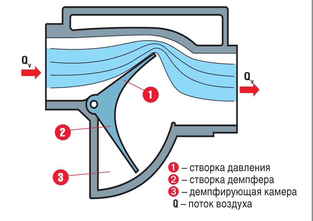
The principle of its operation is quite simple: the air consumed by the motor passes through the inlet, and depending on the intensity (count the mass of air per unit time) rejects the measuring flap by a certain angle. A movable contact is installed on the damper axis, which runs along the path of our long-suffering board from the first picture.
Options for solving the problem:
1. Buy a new DMRV - costs space money 35,000-60000 rubles, comparable to the cost of a car.
2. Buy BU DMRV - 30 years of operation, no guarantees, costs 3000 - 5000 rubles.
3. Buy a new board (non-original, made in small batches) - the price is 300 rubles + forwarding, it looks like this:
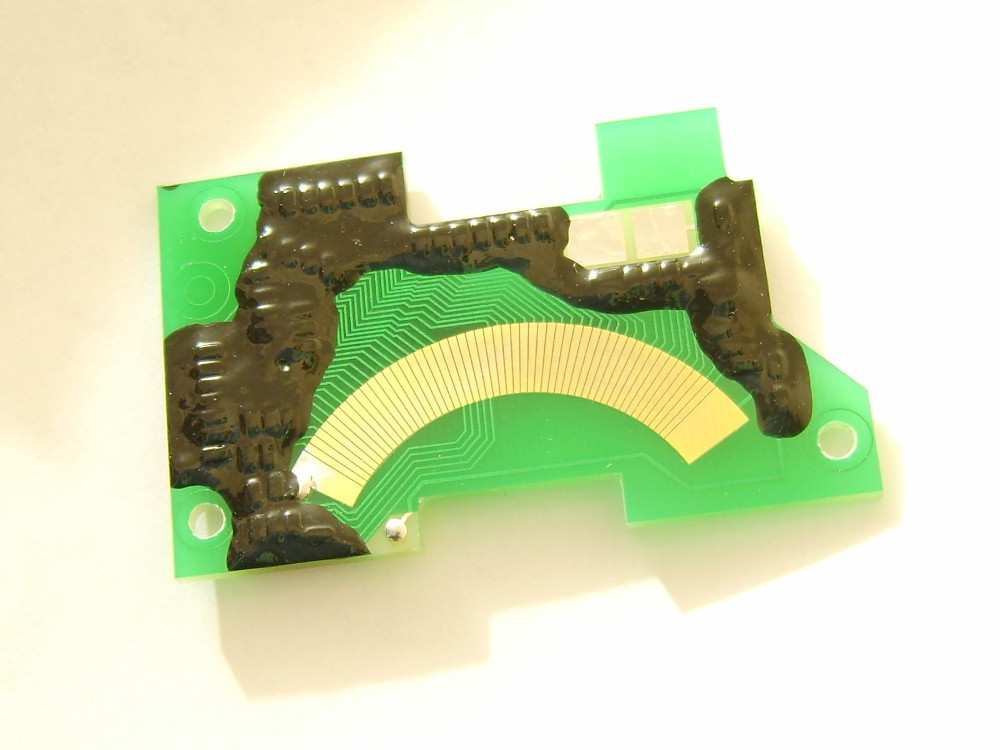
As you can see, the design is different from the factory one. Reliability is in question, on the Internet you can find negative reviews about the alleged fragility of this decision, confirmed by photographs of worn boards of this type.
4. Buy a modern type air-cooled air flow sensor without moving parts + the so-called converter - the price of the issue is a little frightening, it will also be necessary to adapt the intake tract, increase the length of the pipes, etc.
5. Come up with something of your own .
For me, the choice was obvious.
I decided to leave the mechanical part, as I did not find any signs of wear. I think it will last longer than the rest of the car.
The task is a little simplified, it is necessary to convert the angle of rotation into voltage. Although no, wait, it's not that simple ... The thing is that, as I said, the brain is pretty stupid here and, accordingly, it wants to receive as much data as possible on the input. This was reflected in the design of the DMRV - the graph of the dependence of the output voltage on the angle of rotation of the damper axis is non-linear, and an additional complexity - it is scaled by the resistance of the air temperature sensor, which is also built into the DMRV. Accordingly, the characteristic of the sensor should vary depending on the air temperature.
The search for a ready-made circuit solution did not lead to success. The problem with the wear and tear of a DFID of this type has affected many, many topics in specialized forums where people discuss dozens of pages on how to solve it.
To begin with, I would like to get data on the angle of rotation of the axis. I immediately discarded the variable resistors and other mechanics as unreliable. An optical sensor is good, but dust can cause trouble, and there is enough dust on the road. Magnetic sensors are probably what you need.
Found this one: KMA-200 .
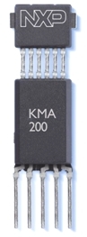
I couldn’t buy it right off the beaten track. And accidentally stumbled upon such a ready-made TPS in which the KMA-200 was used.
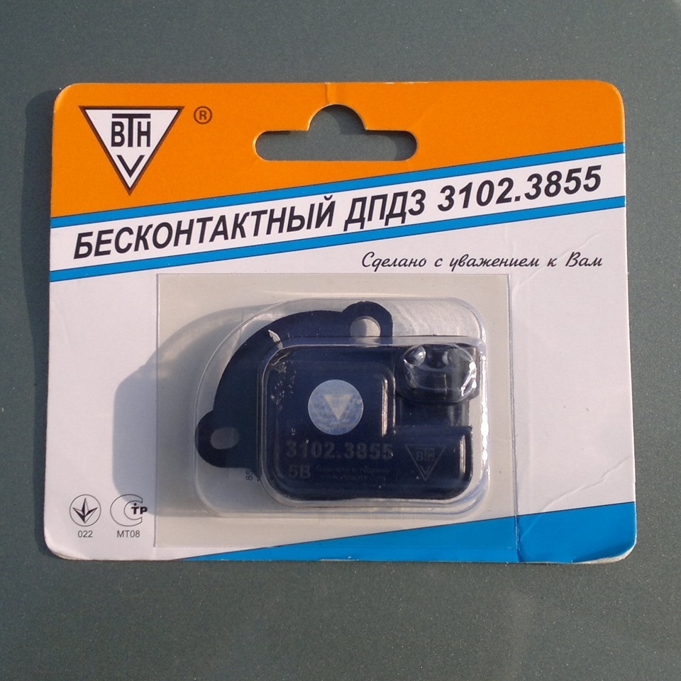
In the load I get a magnet with a mount, the sensor is already on the board with the necessary harness, covered with varnish that protects against moisture and static. I found a similar project by the way .
Excellent!
At the output of such a sensor, the voltage is from 0 to 5 volts. The dependence on the rotation angle is linear. We need to somehow transform it into the characteristic we need. Analog circuits in principle could provide this, but would be rather difficult in design and commissioning, for example, some kind of integrator for operating personnel with thermal compensation, but this is complicated for me ...
Then I remembered that I have a handful of ATiny13, why not use them ?
I sketched and simulated a schematic:
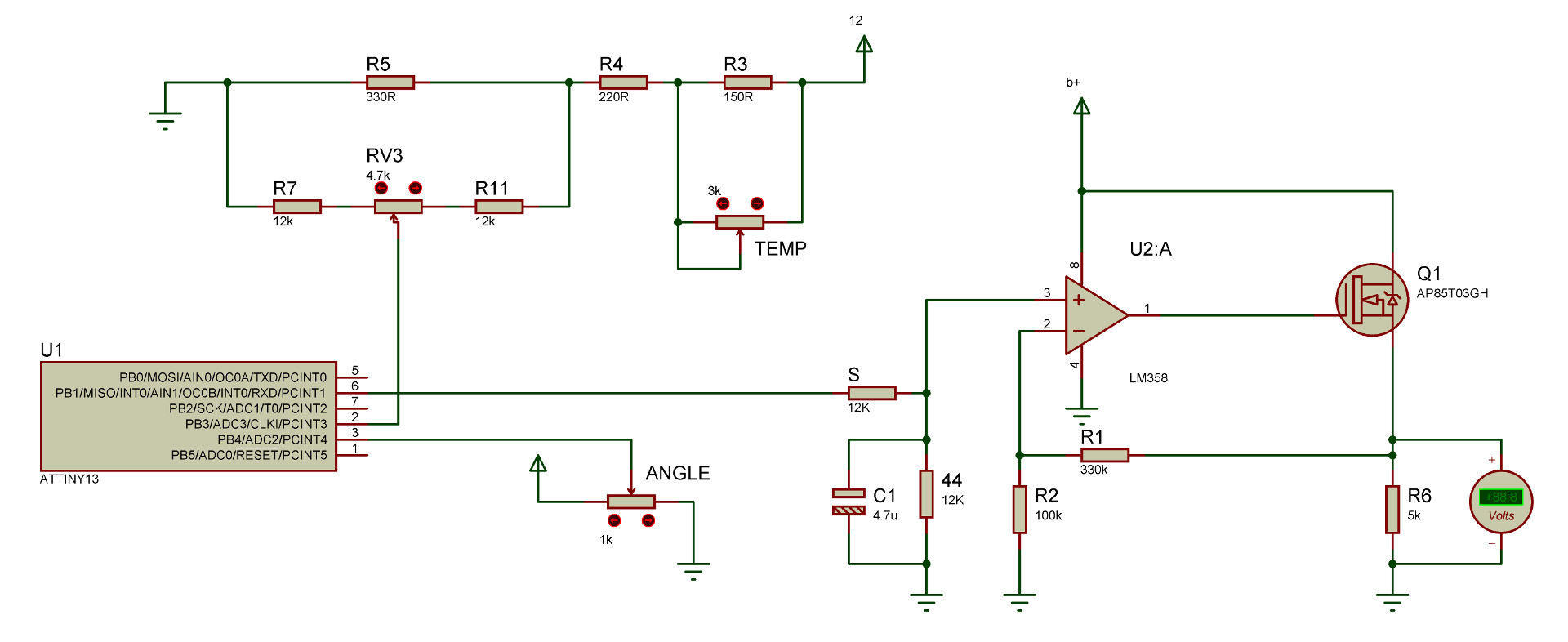
A little about the circuit.
- The microcontroller is clocked from an internal 8MHz oscillator.
- 2 ADC channels were used, the angle of rotation of the damper axis and the voltage level on the resistive divider, of which the temperature sensor is a part, are read.
- PWM output signal with a frequency of about 18 kHz
Next, a simple filter and operational amplifier LM358 from the old motherboard (KU = 1 + (330000/100000) = 4.3), which controls the field operator (from the same motherboard). Maximum output voltage = 4.3 * 2.5 = 10.75V.
Why do you ask a fieldman? And who knows, I will answer you! There will be no excess. Using this circuit, I controlled a powerful load in the form of several automotive lamps connected in parallel just to verify that it could do this too.
In general, all the parts I had were available except for the rotation sensor.
Time to write firmware! This is my first MK firmware, so of course everything is not optimal, and of course I chose the slightly strange BascomAVR tool, in which I have to write on some kind of pseudo-Cubaseic. Obviously, the compiler built in there is not very optimized, the firmware turns out to be bold, and the polynomial interpolation that I wanted to cram there unfortunately did not fit. I had to implement the approximation of three straight segments. Why three? Because it no longer fits (Bascom + 1 kb flash).
$regfile = "attiny13.dat"
$hwstack = 8
$swstack = 16
$framesize = 16
Config Portb.1 = Output
Config Timer0 = Pwm , Prescale = 1 , Compare B Pwm = Clear Up
Config Adc = Single , Prescaler = Auto
Start Timer0
Dim Adcval As Word , Temp As Single
Do
   Adcval = Getadc(2)                       'считываем угол
   Select Case Adcval                      'в зависимости от участка характеристики выбираем нужную прямую
      Case 0 To 306
         Temp = Adcval * 2.2
         Adcval = Temp
      Case 307 To 613
         Temp = Adcval * 0.9377
         Adcval = Temp
         Adcval = Adcval + 384
      Case 614 To 1023
         Temp = Adcval * 0.15
         Adcval = Temp
         Adcval = Adcval + 870
   End Select
   Temp = Adcval * 0.0009765625 'масштабируем полученное значение
   Adcval = Getadc(3)                    'считываем температуру
   Temp = Temp * Adcval               'перемножаем значение температуры и отмасштабированное значение угла поворота
   Pwm0b = Temp * 0.25                'масштабируем полученное значение
Loop
End
$prog &HFF , &H7A , &HFF , &H00                             ' generated. Take care that the chip supports all fuse bytes.
$prog &HFF , &H6A , &HFF , &H00                             ' generated. Take care that the chip supports all fuse bytes.
$prog &HFF , &H7A , &HFF , &H00                             ' generated. Take care that the chip supports all fuse bytes.
$prog &H00 , &H00 , &H00 , &H00                              ' generated. Take care that the chip supports all fuse bytes.
$prog &H00 , &H00 , &H00 , &H00                              ' generated. Take care that the chip supports all fuse bytes.
To figure out the equations of lines, literally in about 10 minutes I drew a dumb softink in Qt Creator, moved the control points, determined the position of the lines.

The red line is the desired characteristic, the blue is the approximation by straight lines. Next, compile and upload the firmware to the emulator. Everything moves as I expected.
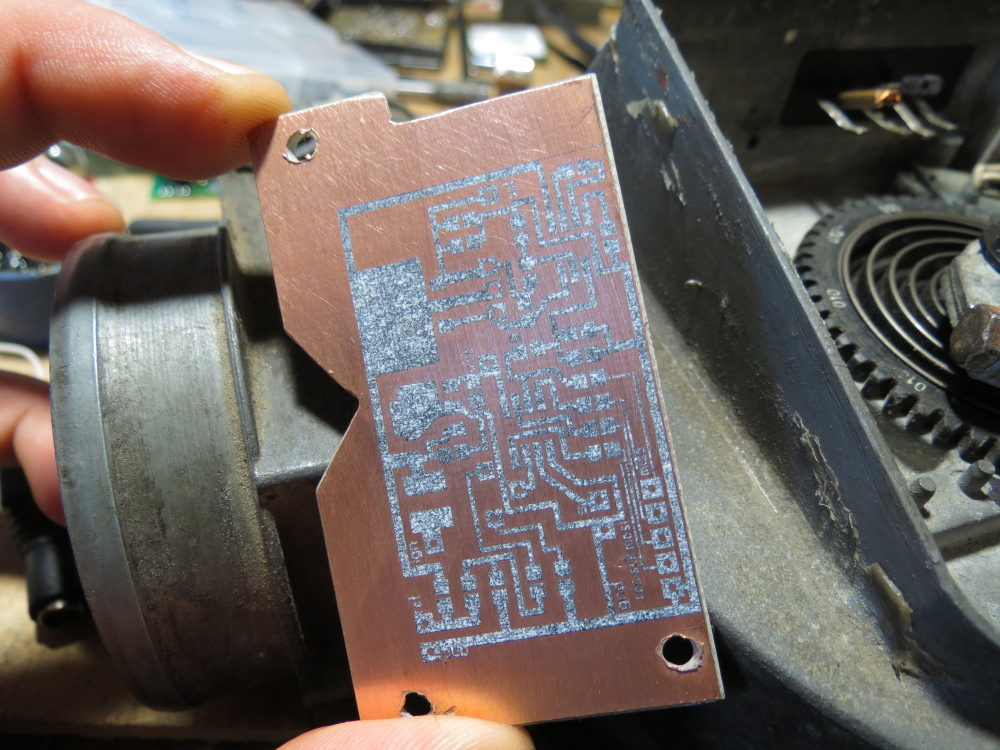
We whip up the board and uncover the laser iron.
We poison, solder, fix the jambs of the wiring (well, where without them).
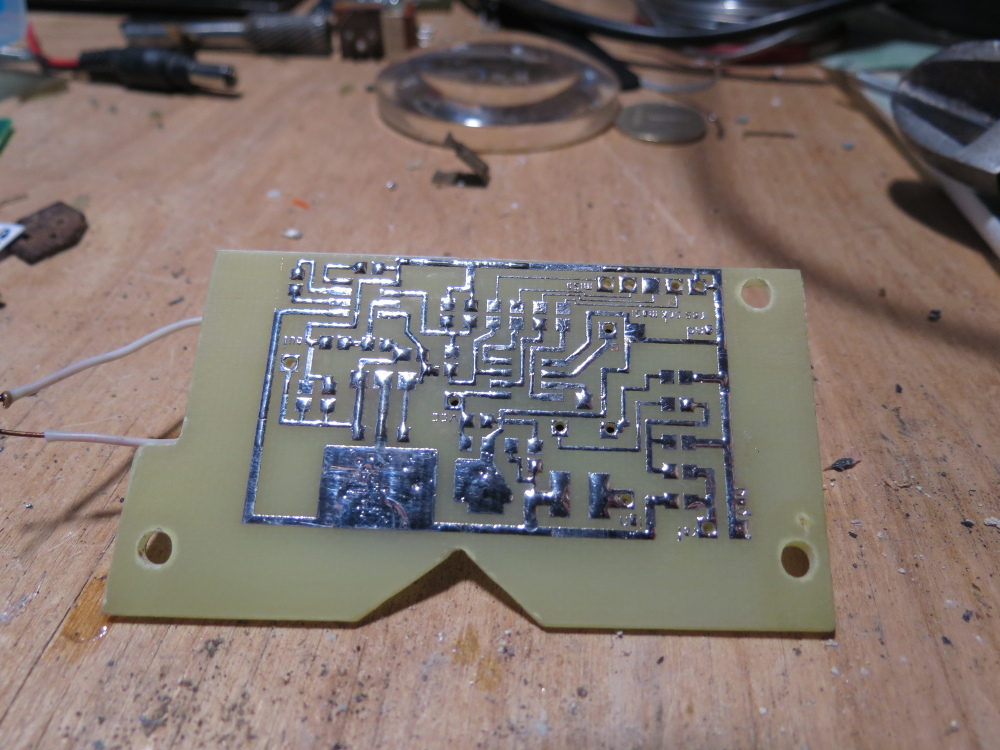

An attentive reader and an experienced radio amateur will notice 2 errors that I made when sealing.
Next, turn on, check the main parameters, and daily run in different modes. Verification showed that everything works as intended. Assembly and installation time on a car.
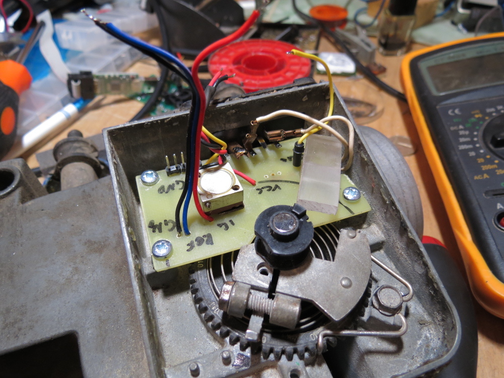
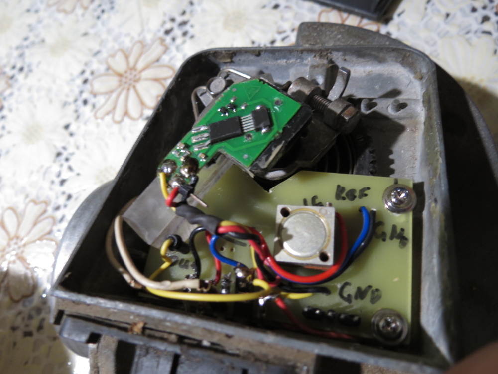
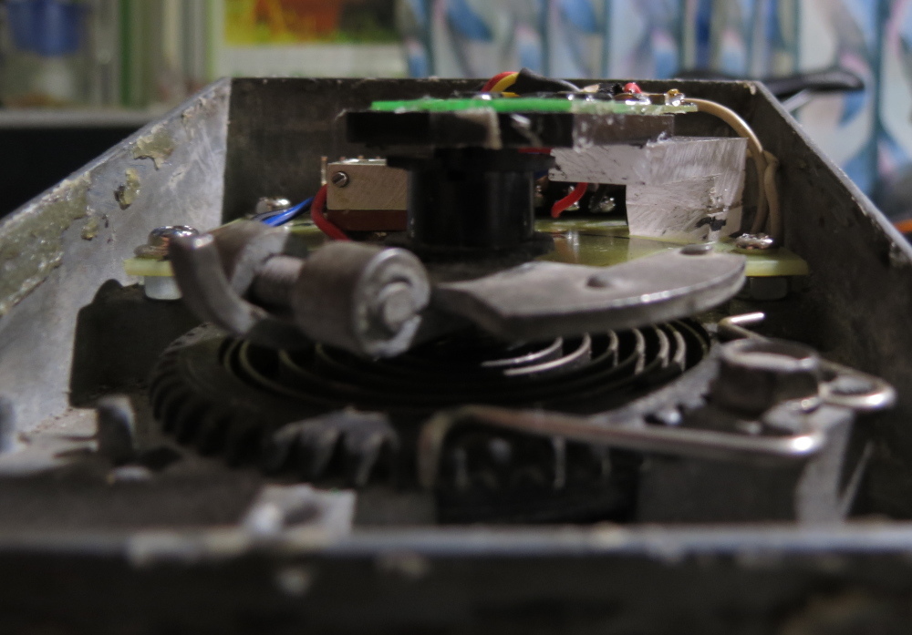
After adjusting with the trimmer, the car starts to work as it should, in the future the gas consumption and dynamics were checked, everything turned out to be normal, those corresponded to the declared characteristics. The machine rode south from central Russia, no problems appeared.
I believe that the first experience in programming microcontrollers, and in principle in creating circuits, was successful for me. Of course there are flaws: for example, choosing a programming environment. In the next project, I already used CVAVR, the firmware is much more compact. The choice of the microcontroller could also be called unsuccessful, although I did not choose it, I had it, and I had a desire to use it. Right after finishing work with this project, I ordered several ATiny85, which have 8 times more memory, but while they were sending this car, they suddenly bought it, and the DMRV was left with an not ideal algorithm).