Another smart home. Part Four - connect the intercom

As I already said - the project does not stand still, but is gradually developing. Therefore, meet the fourth part. In it I will talk about connecting a doorphone.
I will briefly describe how it was done initially. Outside, an ordinary intercom door station with a camera is installed. All the interiors related to the audio section were removed, the camera is connected to the video recorder, the call button and the electromechanical lock were connected to their controllers. Everything worked, everything was fine. A letter arrived saying that the doorbell was ringing - who looked at the record. But I wanted more, namely, the possibility of dialing into a mobile phone, and talking on it with people coming.
It turned out that there is such a class of devices as “GSM dialer” - it is included in the gap between the call panel and the intercom, when the call button is pressed, it dials a number after a certain time and allows you to communicate through a mobile phone. I'm not really a fan of repeating finished products, so I just bought it. But there was another problem - now the calling panel is untied from my controller. Therefore, we must somehow link two different systems.
After analyzing the operation of the intercom with the call panel, the following was found out. The panel is connected by 4 wires: + 12V, "Audio", "Video" and general. Power is supplied to it only at the moment of pressing the call button, and after a certain time - is removed. The video signal comes directly from the camera, but both the camera and the backlight are connected to the power that comes from the intercom, and it only comes out when the button is pressed. So you need to untie the power of the camera from the power of the audio path, because it must also be connected to the recorder.
On the line “Audio” in the inactive mode there is about + 3V. When you press the call button - this line is attracted to the ground, when you press the button to open the electromechanical lock - + 12V is applied to it.
Thus, it is necessary to make a device that would turn on between the call panel and the intercom, provide the camera and dialer with power, and in normal form issue commands for my controller. A video splitter is also necessary, because practice has shown that if you just connect the video inputs of the intercom and recorder in parallel and connect them to the camera output, then everything works fine, but it’s wrong and there is no guarantee that it will work normally on a cable 20 meters long -thirty.

In a nutshell, I will describe what is on the diagram. The video splitter is assembled on the AD812 op-amp. Pressing the call button detects the Q1-Q2-Relay3 circuit; pressing the lock release button - circuit D5-Q3-Relay 2; when power is supplied to the door station - Relay 1 relay is activated.
We draw a board, we poison, we collect.
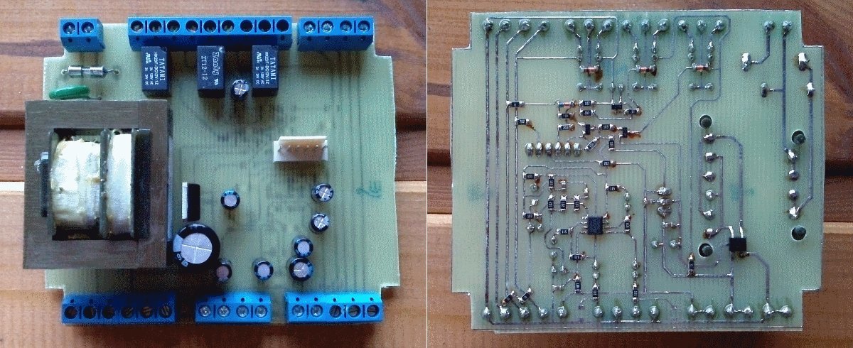
Mount.
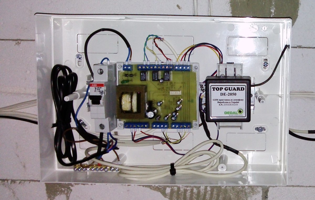
The logic of work is as follows: when the call button is pressed, power is supplied to the call panel, relay 1 is activated, which in the lighting controller turns on the light in front of the gate. Also, while holding the button, relay 3 is activated, which on the other controller records the time and event number. When you open the lock from the intercom - relay 2 is activated, which opens the electromechanical lock through the lighting controller. In addition, for convenience, a two-channel remote control receiver is connected in parallel, allowing you to open the lock on the gate, or turn on the light at the entrance.
The signal from the camera, through the splitter of the video signal, is fed to the intercom and video recorder, from which it then goes to the web interface.

Scheme files (TinyCAD) and board layout (Sprint-Layout) - here .
Links to previous parts: