Experience in using Mikrotik CHR to organize virtual routing
In the article I will present the result of solving the problem of organizing routing between virtual machines on VMware using MikroTik CHR, and with organizing VPN access to virtual machines from an external network.
Introduction
Define the original problem:
- Available server with a memory capacity of 96 GB, 24 CPU and 22 TB of disk space
- 2 lines are connected to the server:
- one is for managing and managing VMware;
- the second comes with two VLANs - one for access to the internal network of the organization and with access to the Internet, from the second come real addresses.
In order to no longer use the organization's address space, it is necessary to define your own address space inside the server for a resource of 3 virtual machines and close the resource for access of other resources from 3 machines.
It is necessary to block traffic from virtual machines that does not go to the organization's proxies.
Each resource of three virtual machines is designed for one person, he also needs to provide access to work from home.
On the server is VMware ESXi 6, for routing will be used MikroTik CHR 6.42
Configure VMware
As already determined, two VLANs come to the server, one will serve for access of virtual machines to the organization’s network and access to the Internet through the organization’s proxy, the second is necessary for having a real address and access to virtual machines from outside.
Using VMware on a virtual switch, create separate interfaces:
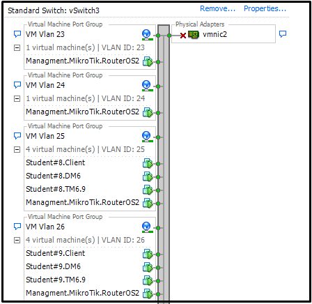
Each created interface is bound to a virtual machine with MikroTik CHR and to 3 virtual machines from the pool. For example, for machines with the identifier Student # 8, the virtual interface VM Vlan 25 is assigned.
As a result, we get the following settings for a virtual machine with MikroTik CHR:
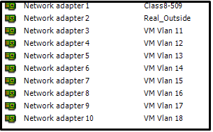
As you can see the Class8-509 interface for access to the internal network and Real_Outside for the real address.
Configure MikroTik CHR
Initially, we will determine the friendly names of the interfaces and give comments to understand which interface is intended for which pool of virtual machines.
/interface ethernet
set [ find default-name=ether1 ] comment="VLAN ID 111 Uplink to Company" name=\
    Class8_509_VM
set [ find default-name=ether4 ] comment="Interface VM Vlan 12 for Student #1" \
    name=Int_VM_Vlan12
set [ find default-name=ether6 ] comment="Interface VM Vlan 14 for Student #3" \
    name=Int_VM_Vlan14
set [ find default-name=ether7 ] comment="Interface VM Vlan 15  for Student #4" \
    name=Int_VM_Vlan15
set [ find default-name=ether8 ] comment="Interface VM Vlan 16  for Student #5" \
    name=Int_VM_Vlan16
set [ find default-name=ether2 ] comment="Interface Vlan 1111 Real_Outside" \
    name=Real_Outside
We will assign an IP address to each interface, including an interface that will have a real address.
/ip address
add address=*.*.*.*/27 interface=Class8_509_VM network=*.*.*.*
add address=10.0.11.1/29 interface=Int_VM_Vlan11 network=10.0.11.0
add address=10.0.12.1/29 interface=Int_VM_Vlan12 network=10.0.12.0
add address=10.0.13.1/29 interface=Int_VM_Vlan13 network=10.0.13.0
add address=*.*.*.*/27 interface=Real_Outside network=*.*.*.*
Define a set of networks. In each pool of machines on one virtual machine, Windows Server 2012 is installed on which AD and DNS are configured, so for each network the IP address of this virtual machine will act as DNS.
/ip dhcp-server network
add address=10.0.11.0/29 dns-server=10.0.11.4 gateway=10.0.11.1
add address=10.0.12.0/29 dns-server=10.0.12.5 gateway=10.0.12.1
add address=10.0.13.0/29 dns-server=10.0.13.5 gateway=10.0.13.1
For each interface, we define the address pool that the DHCP server will issue and activate Add ARP For Leases . Thus, preventing the manual assignment of IP addresses for the virtual machine.
Add ARP For Leases - Creates MAC - IP mapping in the table of ARP records for clients who have leased from DHCP and, together with IP / ARP, allows organizing MAC filtering for microtics.
Since it is necessary to provide access to virtual machines from the Internet, we will immediately prepare a pool of addresses for clients when they will be connected via L2TP / IPsec.
/ip pool
add name=dhcp_pool_for_vm_vlan11 ranges=10.0.11.2-10.0.11.6
add name=dhcp_pool_for_vm_vlan12 ranges=10.0.12.2-10.0.12.6
add name=dhcp_pool_for_vm_vlan13 ranges=10.0.13.2-10.0.13.6
#Пул адресов для l2tp
add name=student1_l2tp_pool ranges=10.1.12.2-10.1.12.4
add name=student2_l2tp_pool ranges=10.1.13.2-10.1.13.4
add name=student3_l2tp_pool ranges=10.1.14.2-10.1.14.4
/ip dhcp-server
add add-arp=yes address-pool=dhcp_pool_for_vm_vlan11 disabled=no interface=\
    Int_VM_Vlan11 lease-time=1h name=dhcp_for_vm_vlan11
add add-arp=yes address-pool=dhcp_pool_for_vm_vlan12 disabled=no interface=\
    Int_VM_Vlan12 lease-time=1h name=dhcp_for_vm_vlan12
add add-arp=yes address-pool=dhcp_pool_for_vm_vlan13 disabled=no interface=\
    Int_VM_Vlan13 lease-time=1h name=dhcp_for_vm_vlan13
The new versions of RouterOS now have the ability to create lists, so we will combine all local interfaces into one list to facilitate firewall settings.
/interface list member
add interface=Int_VM_Vlan11 list=local_vm
add interface=Int_VM_Vlan12 list=local_vm
add interface=Int_VM_Vlan13 list=local_vm
We define a list of proxy IP addresses and specify in the firewall rules that traffic from all local interfaces, if it does not go to proxy addresses, will be blocked. We’ll immediately point out the rule to deny ICMP and block traffic between local interfaces.
/ip firewall address-list
add address=192.168.3.3 list=Proxy
add address=192.168.3.1 list=Proxy
add address=192.168.3.5 list=Proxy
add address=192.168.3.7 list=Proxy
/ip firewall filter
add action=drop chain=forward comment="Block If Not Proxy Address" \
    dst-address-list=!Proxy in-interface-list=local_vm
add action=drop chain=input comment="Block ping" \
    in-interface-list=local_vm protocol=icmp
add action=drop chain=forward comment="Block ping between interface" \
    in-interface-list=local_vm out-interface-list=local_vm
We also define NAT, in which all traffic from local addresses will go through an interface that looks into the organization’s network.
Configure MikroTik CHR: L2TP / IPsec
To organize access from an external network, activate the L2TP server and create for each user their credentials and their own interface. Each user will be able to create only one connection at a time. Since some users use Windows 10, in the security settings we additionally activate the 3DES encryption algorithm.
In the firewall settings, we indicate that each user can only access his own network (to a specific local interface) via certain ports (RPD and SSH) and block any other traffic. Additionally, allow access for l2tp from an interface that has a real address.
To ease the load on the organization’s network, for each user we will make a speed limit.
As a result, we get the following settings, I will give part of the settings for one user.
/interface l2tp-server
add comment="Interface L2TP for Student#1" name=int_l2tp_student1 user=student1
/ppp profile
add change-tcp-mss=yes comment="Student1 Profile for L2TP, Rate Limits 3M/3M" \
    local-address=10.1.12.1 name=student1_l2tp_profile only-one=yes rate-limit=\
    3M/3M remote-address=student1_l2tp_pool use-compression=yes use-encryption=\
    required use-upnp=no
/ip firewall filter
add action=accept chain=input in-interface=Real_Outside port=1701,500,5000 \
    protocol=udp
add action=accept chain=input in-interface=Real_Outside protocol=ipsec-esp
#Доступ с l2tp только на определенный локальный интерфейс
add action=accept chain=forward comment="Student #1 L2TP to Vlan 12" \
    in-interface=int_l2tp_student1 out-interface=Int_VM_Vlan12 port=3389,22 \
    protocol=tcp
add action=accept chain=forward in-interface=Int_VM_Vlan12 out-interface=\
    int_l2tp_student1
add action=drop chain=forward in-interface=int_l2tp_student1
/ppp secret
add comment="Student1 Auth Data" name=student1 password=******** profile=
    student1_l2tp_profile service=l2tp
In addition to setting up the connection on the client’s home machine, the client additionally prescribes the route to the network allowed to him, however, thanks to the firewall rules, if the client specified a route not to his network, then he will not be able to access the virtual machines of the specified network.
Traffic marking
Since we have two Internet connections, we need to correctly send incoming traffic back through the desired interface. Therefore, we use the capabilities of Mikrotik in traffic labeling.
/ip firewall mangle
add action=mark-connection chain=input comment="Mangle Real_Outside traffic" \
    in-interface=Real_Outside new-connection-mark=realOutMark passthrough=yes
add action=mark-connection chain=input comment="Mangle Class8_509_VM Traffic" \
    in-interface=Class8_509_VM new-connection-mark=classVmMark passthrough=yes
add action=mark-routing chain=output comment="Rout out Real_Outside" \
    connection-mark=realOutMark new-routing-mark=routReakOut passthrough=no
add action=mark-routing chain=output comment="Rout out Class8-509 VM" \
    connection-mark=classVmMark new-routing-mark=routClass8-509VM passthrough=\
    no
/ip route
add distance=1 gateway=195.69.204.161 routing-mark=routReakOut
add distance=1 gateway=192.168.145.30 routing-mark=routClass8-509VM
add check-gateway=ping distance=1 gateway=Class8_509_VM
Ssh block list
Since our MikroTik has a real address, there are attempts to select a password from the Internet using the SSH protocol, so we will add a number of rules to the firewall to block such IP addresses.
add action=drop chain=input comment="drop ssh brute forcers" dst-port=22 \
    protocol=tcp src-address-list=ssh_blacklist
add action=add-src-to-address-list address-list=ssh_blacklist \
    address-list-timeout=14w2d chain=input connection-state=new dst-port=22 \
    protocol=tcp
add action=add-src-to-address-list address-list=ssh_stage3 \
    address-list-timeout=10m chain=input connection-state=new dst-port=22 \
    protocol=tcp
add action=add-src-to-address-list address-list=ssh_stage2 \
    address-list-timeout=10m chain=input connection-state=new dst-port=22 \
    protocol=tcp
add action=add-src-to-address-list address-list=ssh_stage1 \
    address-list-timeout=10m chain=input connection-state=new dst-port=22 \
    protocol=tcp
add action=drop chain=forward comment="drop ssh brute downstream" dst-port=22 \
    protocol=tcp
At the time of this writing, there were about 400 addresses in the lock lists.
Total
As a result, we get the configured virtual mikrotik at the output, which performs traffic routing, provides the ability to connect from the Internet via l2tp / ipsec, and has firewall settings for distinguishing between users and interfaces.
UPD
Thanks gecube . For MikroTik CHR, you must purchase a license, otherwise each interface is limited to 1 Mbps, or you can activate trial for 60 days with full functionality. Cost and gradation of licenses. . An unlimited license is limited only by the speed of your interfaces.