But not to design for us a system for managing the production of IT products. Part 3. Infrastructure Support
- Tutorial
In the previous parts Summary:
“Part 1”
I Introduction
II Analysis of the solutions market
1. Standardization of the functions of systems on the market
2. Disadvantages of existing systems
3. Challenges for creating a support system for the production of information systems
III Designing the basic structure of the system
1. Division of problems to be solved by type
“Part 2”
2. Requirements and tasks for them
3. Specifications and tasks for them
4. Assemblies and tasks for them
5. Analysis of the design phase
We continue the destruction of familiar patterns that we started in the previous part and the construction of other new ones.
Let us briefly discuss the organization of the process from the point of view of project management. In view of the fact that we are talking about the production of more or less unique products, the essence - “Project” has already been mentioned in the previous sections.
Since most software development methodologies promote a healthy iterative approach, we add another element that divides the project into its smaller parts - iterations. In this case, we will not be sprayed on the entire process of production of information systems, but we will organize work in iterations only for activities that are directly related to the implementation of requirements in the code. This will slightly reduce the scalability of our system, but at the very beginning we noted that the versatility of existing products reduces their technological suitability. Therefore, we will tailor the system for ourselves.
In standard trackers, iterations are most often indicated in tasks using labels, epics, or other additional features. We will introduce an additional entity “Iteration”.
A possible data model is presented in Fig. 7.
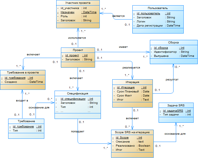
Figure 7. - Model of project organization We will
provide the opportunity to type “Specifications” into iteration through the new “Scope to iteration” element. This will solve the problem, the inevitability of implementing one specification in several iterations. The vast majority of projects are completely imperfect and this chance may turn out to be quite out of place.
In the “Scope to iterate” element, we add the “Implemented” attribute, thus organizing a check list to indicate success (or failure). Now, when implementing the specification in the code and after carefully checking it, you can “jump through” it in the Scope list for iteration. And if desired, this process can even be automated, for example, according to the status of completed tasks. IT managers are very fond of such visual tuning in the style of minimalism - only he, a list of tasks and a tick about its implementation, nothing superfluous, distracting attention.
Now let's go from the back of Scope. There, in the rear, where it is expected to receive confirmation of what was planned, we tie “Scope to iteration” on “SRS Tasks”. Thus, we will be able to track all the activities performed according to the specifications, committed as part of the iteration. Those who carefully read the article must have noticed that now we have formed an excessive connection: “The SRS task” is connected directly with the “Specification” and, in addition, through the “Scope for iteration”. In these circumstances, who is already used to resolving such difficulties. For example, you can remove the connection to the specification, but this will complicate the work with data. In particular, the SRS task cannot be set without iteration. But you never know what. Or leave a redundant link, but ensure the consistency of the data in the links. There are plenty of funds for this too.
And as is customary in a decent society, each iteration should end with a final assembly with implemented functionality, in accordance with the obligations undertaken (specifications for iteration). To do this, set the link to "Assembly" in "Iteration".
We test our model with this scenario:
For our data model, this scenario is easy.
So what do we have? We can get Scope by iteration, as a context of the implemented functionality. View task lists by type, by artist, etc. as a performance plan. See reports on what and how of this. And in the end, get the current version of the product.
Work on changing (managing) requirements can be performed outside of iterations. Although if you fundamentally include them in its framework, you can add another entity “Scope of requirements for iteration” and inherit it from a common ancestor, see fig. 8. Similarly, in case of urgent need, assembly work can also be included in the iteration.

Figure 8. - Scope organization model for iteration
Considering the topic of assemblies at the very beginning, we touched on the problem of integration solutions, which implies the inclusion of several assemblies of different subsystems in a product that are developing into a single software package. A dilemma arises in this plane: on the one hand, several relevant assemblies are involved simultaneously in one project, and on the other, the same assembly can get into different projects and enter different end products. Forcibly hangs the need to include another element - the "Product".
In fact, the target product should be the result of the entire process of creating an information system in a project.
For such a turn, we now need to remove the existing “Assembly” connection with the “Project”, and install it through the additional “Assembly in the Product” element, as shown in Fig. 9.

Figure 9. - Model for organizing accounting for the target product
Since collecting the new version of the target product bit by bit does not always require reassembling these particles themselves (its subsystems), we will indicate the version of the product for which the selected assembly is relevant for “Assembly in the product” . The solution is so-so, and of course this mechanism can be implemented by painting.
As an option in this solution, the assembly of each subsystem can be represented as a separate product and form the target product from other more elementary products.
In this publication, we have more than once casually touched upon the topic of communicating the participants in the project. For example, they considered commenting on requirements and specifications during their discussion. In standard products, most often there is still a useful function - notifications, informing participants about the assigned task, mentioning in comments, etc.
But here is another interesting topic that is not often found in the proposed products - holding meetings and rallies within the framework of the system under consideration. It’s convenient, when planning a meeting, to determine the issues under discussion on the basis of the set of elements that we operate in our system: requirements, specifications, assemblies, iterations, tasks, etc. Again, the participants in the discussions are always at hand, in the form of stakeholders (project stakeholders). You can even prepare in advance draft solutions to problems, and allow those invited to familiarize themselves with the agenda the day before.
A possible data model is presented in Fig. 10.

Figure 10. - Meeting organization model
For example, imagine this picture: several teams participating in the project remotely communicate by phone or using sound-absorbing messengers and discuss the “burning” project. Everything is already sparkling and heated to the limit. Not scary yet? Then exacerbate. Analysts, testers and developers, and project managers participate in the discussion. At first, if you do not twist one topic - who is to blame? Presented?
Well, let's say the first question was discussed, they screamed, opened their eyes to each other, who they really are. It's time to move on to the second - what to do? This is where a pre-prepared list of questions may come in handy, and even better, a list of draft decisions prepared for it, which all discussion participants see on their screens. Now imagine that anyone can go directly from a question, for example, into a demand or task for its implementation. See comments, reports. Poke someone's nose at numbers and facts. And just as easily and naturally return to the page with questions. Conveniently?
But that is not all. After discussing the issue, you can immediately formulate decisions on it, fixing a plan for further actions, which in the future can be transformed into tasks for performers. And that’s all, all the participants quickly see it all at once and silently agree, or loudly resent. And most importantly, all this is fixed in the system and you can’t cut it down with an ax. And now you don’t need to attach photos with hand-drawn scribbles. Such blitz rallies are very productive and effective in terms of correcting the situation for the better.
In the system, according to the lists of meetings of the project, you can easily brush up on the old battles and take pride in promptly and effectively taken measures that eliminated all the obstacles that arose on the way to creating the product.
“Part 1”
I Introduction
II Analysis of the solutions market
1. Standardization of the functions of systems on the market
2. Disadvantages of existing systems
3. Challenges for creating a support system for the production of information systems
III Designing the basic structure of the system
1. Division of problems to be solved by type
“Part 2”
2. Requirements and tasks for them
3. Specifications and tasks for them
4. Assemblies and tasks for them
5. Analysis of the design phase
IV DESIGN OF SYSTEM INFRASTRUCTURE ELEMENTS
Among the countless kinds of magic, creation provides greater freedom. Everyone creates in his own way. Try your best and find your own form.
(Fairy Tail Tale)
We continue the destruction of familiar patterns that we started in the previous part and the construction of other new ones.
1. General project infrastructure
Let us briefly discuss the organization of the process from the point of view of project management. In view of the fact that we are talking about the production of more or less unique products, the essence - “Project” has already been mentioned in the previous sections.
Since most software development methodologies promote a healthy iterative approach, we add another element that divides the project into its smaller parts - iterations. In this case, we will not be sprayed on the entire process of production of information systems, but we will organize work in iterations only for activities that are directly related to the implementation of requirements in the code. This will slightly reduce the scalability of our system, but at the very beginning we noted that the versatility of existing products reduces their technological suitability. Therefore, we will tailor the system for ourselves.
In standard trackers, iterations are most often indicated in tasks using labels, epics, or other additional features. We will introduce an additional entity “Iteration”.
A possible data model is presented in Fig. 7.
Figure 7. - Model of project organization We will
provide the opportunity to type “Specifications” into iteration through the new “Scope to iteration” element. This will solve the problem, the inevitability of implementing one specification in several iterations. The vast majority of projects are completely imperfect and this chance may turn out to be quite out of place.
In the “Scope to iterate” element, we add the “Implemented” attribute, thus organizing a check list to indicate success (or failure). Now, when implementing the specification in the code and after carefully checking it, you can “jump through” it in the Scope list for iteration. And if desired, this process can even be automated, for example, according to the status of completed tasks. IT managers are very fond of such visual tuning in the style of minimalism - only he, a list of tasks and a tick about its implementation, nothing superfluous, distracting attention.
Now let's go from the back of Scope. There, in the rear, where it is expected to receive confirmation of what was planned, we tie “Scope to iteration” on “SRS Tasks”. Thus, we will be able to track all the activities performed according to the specifications, committed as part of the iteration. Those who carefully read the article must have noticed that now we have formed an excessive connection: “The SRS task” is connected directly with the “Specification” and, in addition, through the “Scope for iteration”. In these circumstances, who is already used to resolving such difficulties. For example, you can remove the connection to the specification, but this will complicate the work with data. In particular, the SRS task cannot be set without iteration. But you never know what. Or leave a redundant link, but ensure the consistency of the data in the links. There are plenty of funds for this too.
And as is customary in a decent society, each iteration should end with a final assembly with implemented functionality, in accordance with the obligations undertaken (specifications for iteration). To do this, set the link to "Assembly" in "Iteration".
We test our model with this scenario:
- For iteration, a certain number of specifications are included, included in Scope;
- By Scope, an SRS task is created for each line to implement the specification in code;
- A new assembly is registered in the system;
- After all development tasks are completed, the assembly tasks are set;
- By Scope, an SRS Test Task is created for each line;
- After installing the assembly on the stands, testing tasks are performed;
- By Scope, for each line that has not passed successful testing, SRS Tasks for fixing errors are set;
- Repeats from step 4 until errors are detected;
- The assembly that is extreme in the iteration is assembled, and the results of the iteration are summarized.
For our data model, this scenario is easy.
So what do we have? We can get Scope by iteration, as a context of the implemented functionality. View task lists by type, by artist, etc. as a performance plan. See reports on what and how of this. And in the end, get the current version of the product.
Work on changing (managing) requirements can be performed outside of iterations. Although if you fundamentally include them in its framework, you can add another entity “Scope of requirements for iteration” and inherit it from a common ancestor, see fig. 8. Similarly, in case of urgent need, assembly work can also be included in the iteration.
Figure 8. - Scope organization model for iteration
2. Integration solutions
Considering the topic of assemblies at the very beginning, we touched on the problem of integration solutions, which implies the inclusion of several assemblies of different subsystems in a product that are developing into a single software package. A dilemma arises in this plane: on the one hand, several relevant assemblies are involved simultaneously in one project, and on the other, the same assembly can get into different projects and enter different end products. Forcibly hangs the need to include another element - the "Product".
In fact, the target product should be the result of the entire process of creating an information system in a project.
For such a turn, we now need to remove the existing “Assembly” connection with the “Project”, and install it through the additional “Assembly in the Product” element, as shown in Fig. 9.
Figure 9. - Model for organizing accounting for the target product
Since collecting the new version of the target product bit by bit does not always require reassembling these particles themselves (its subsystems), we will indicate the version of the product for which the selected assembly is relevant for “Assembly in the product” . The solution is so-so, and of course this mechanism can be implemented by painting.
As an option in this solution, the assembly of each subsystem can be represented as a separate product and form the target product from other more elementary products.
3. Communication support
In this publication, we have more than once casually touched upon the topic of communicating the participants in the project. For example, they considered commenting on requirements and specifications during their discussion. In standard products, most often there is still a useful function - notifications, informing participants about the assigned task, mentioning in comments, etc.
But here is another interesting topic that is not often found in the proposed products - holding meetings and rallies within the framework of the system under consideration. It’s convenient, when planning a meeting, to determine the issues under discussion on the basis of the set of elements that we operate in our system: requirements, specifications, assemblies, iterations, tasks, etc. Again, the participants in the discussions are always at hand, in the form of stakeholders (project stakeholders). You can even prepare in advance draft solutions to problems, and allow those invited to familiarize themselves with the agenda the day before.
A possible data model is presented in Fig. 10.
Figure 10. - Meeting organization model
For example, imagine this picture: several teams participating in the project remotely communicate by phone or using sound-absorbing messengers and discuss the “burning” project. Everything is already sparkling and heated to the limit. Not scary yet? Then exacerbate. Analysts, testers and developers, and project managers participate in the discussion. At first, if you do not twist one topic - who is to blame? Presented?
Well, let's say the first question was discussed, they screamed, opened their eyes to each other, who they really are. It's time to move on to the second - what to do? This is where a pre-prepared list of questions may come in handy, and even better, a list of draft decisions prepared for it, which all discussion participants see on their screens. Now imagine that anyone can go directly from a question, for example, into a demand or task for its implementation. See comments, reports. Poke someone's nose at numbers and facts. And just as easily and naturally return to the page with questions. Conveniently?
But that is not all. After discussing the issue, you can immediately formulate decisions on it, fixing a plan for further actions, which in the future can be transformed into tasks for performers. And that’s all, all the participants quickly see it all at once and silently agree, or loudly resent. And most importantly, all this is fixed in the system and you can’t cut it down with an ax. And now you don’t need to attach photos with hand-drawn scribbles. Such blitz rallies are very productive and effective in terms of correcting the situation for the better.
In the system, according to the lists of meetings of the project, you can easily brush up on the old battles and take pride in promptly and effectively taken measures that eliminated all the obstacles that arose on the way to creating the product.