TP-Link T2600G-28MPS: working with PoE, LLDP and Voice VLAN
About six months ago, we published an example of building a Wi-Fi network based on our wireless equipment: access points and a controller. Today we will tell you in detail about the T2600G-28MPS level 2+ switch, which can be used to build wired network segments that provide video surveillance systems, distributed wireless networks, IP-telephony, and also simply perform packet switching.
We do not set ourselves the goal of providing a complete description of all the features of the T2600G-28MPS model, instead we will focus on those functions on which the operation of supported wireless networks and IP-telephony directly depends.
Providing power to terminal equipment is not the easiest task to be solved by network engineers. Of course, you can use external power supplies that come with most models of access points, IP cameras and phones. However, this solution is not scalable, and it is difficult to attribute it to a convenient one: a large number of additional blocks and wires, increased network deployment time, deterioration of the appearance of premises, the impossibility of centralized power management, the inability to guarantee the quality of power, and so on. Instead, an increasing number of network administrators are turning their attention to PoE technology, which allows you to immediately solve all of these problems.
TP-Link T2600G-28MPS has an increased energy budget (up to 384 watts). Today, two IEEE standards are widely used that describe the operation of the technology: 802.3af-2003 and 802.3at-2009. The first of them determines the maximum available power equal to 15.4 watts. The maximum power provided by the second is 30 watts. Simple arithmetic shows that this switch allows you to simultaneously provide power to 802.3af consumers connected to all ports of the device. When connecting more powerful consumers (with support for the 802.3at standard) at the same time, it will not be possible to provide the maximum allowable power to all terminal devices, however, it should be noted that not all 802.3at devices constantly require 25.5 watts of electricity to operate. Such consumption will be rather, an exception, or may be required for a relatively short period of time. In addition, the switch has settings that allow you to resolve the situation in the mode of energy budget deficit. Let's see what the network administrator can manage.
All settings related to PoE technology are collected in the same menu group of the web interface. Using the “PoE Config” item, the administrator can specify the maximum power consumed by the switch to power PoE clients, view and change the current state of the ports, set the interface priority and the class of the connected device, select the time interval and PoE profile.
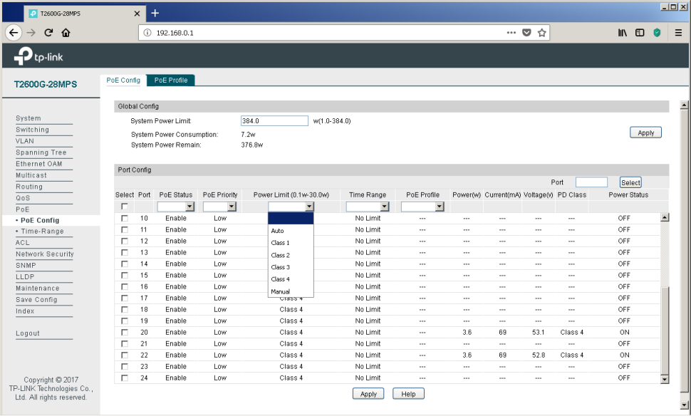
It can be seen from the above screenshot that some devices are connected to ports No. 20 and 22, currently consuming 3.6 watts of electricity each (current - 69 mA and voltage 53.1 V), which corresponds to the fourth class of PoE. We will not make intrigue out of these powered devices - these are our access points of the CAP1200 model .
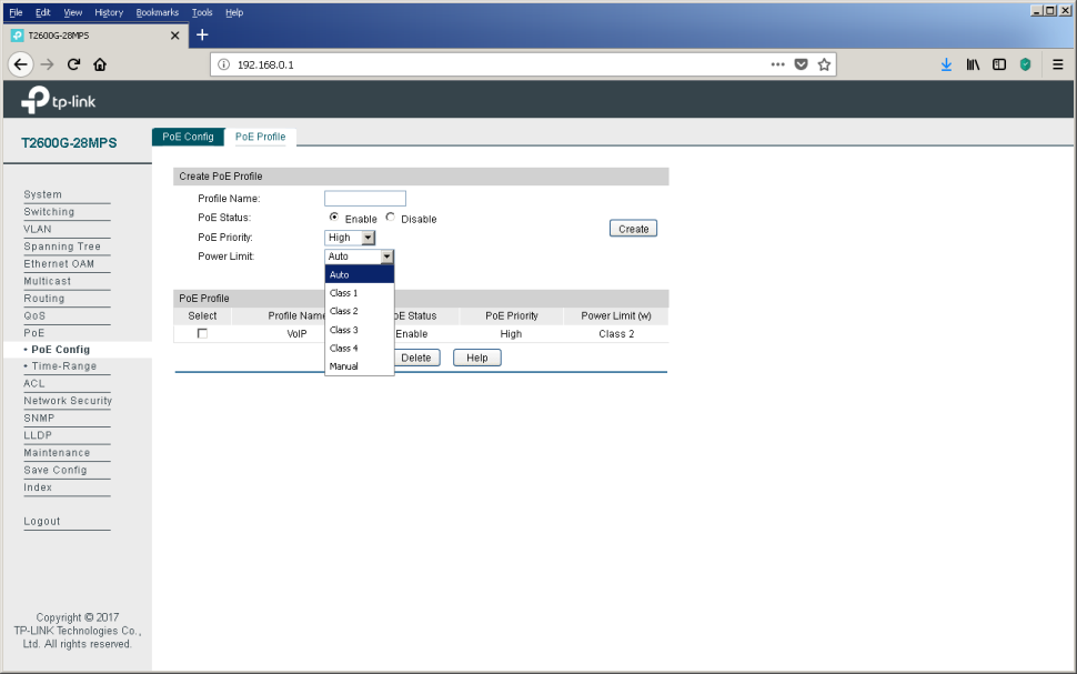
The PoE Profile tab of the same menu item allows you to create energy profiles, which greatly simplifies the configuration of the switch when connecting typical consumers.
Administrators who prefer to work on the command line can also control power through PoE using the power command group.
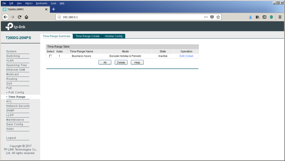
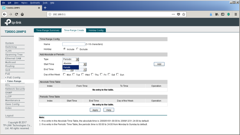
Very often, company executives try to reduce electricity bills, which accountants have to pay monthly. The “Time-Range” item in the same menu group can help them with this. Using this item, the administrator can create a schedule in accordance with which consumers will be catering. So, for example, at night and on weekends, the number of employees present at their workplaces is usually much less than during the so-called business hours. Reducing the number of users leads to a reduction in the load on the network infrastructure - access points will work almost idle. Automatic shutdown of some of them will not affect the level of service provided, as wireless users will be automatically redistributed between the remaining enabled access points. On Monday morning, the backup equipment will be automatically turned on again on schedule, thus preparing everything necessary for the return of our network administrator's colleagues to the office. The process of switching on multiple access points will be routinely processed by a wireless controller, the frequency and radiation power will be redistributed so as to provide the best coverage throughout the territory.
Sometimes PoE devices are installed on sensitive objects, which are strictly prohibited during off-hours. In this case, it will be possible to prevent even more money from being wasted by disabling IP-phones of some employees.
The power schedule is controlled using the “Time-Range” item.
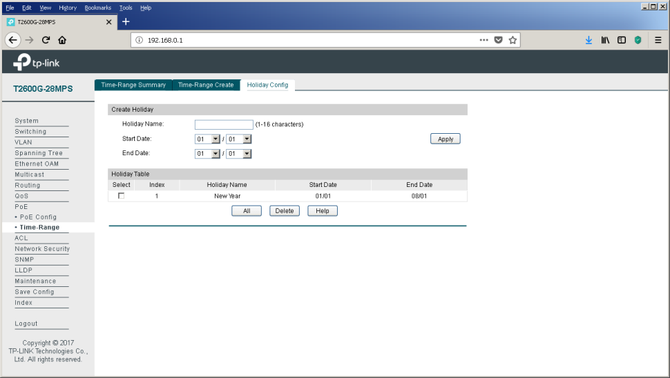
Calculate how much you could save for the New Year holidays this year! And ahead of us is still a great weekend in May.
Link Layer Discovery Protocol (IEEE 802.1ab) - a protocol that allows you to detect neighboring devices, as well as tell neighbors certain information about themselves.
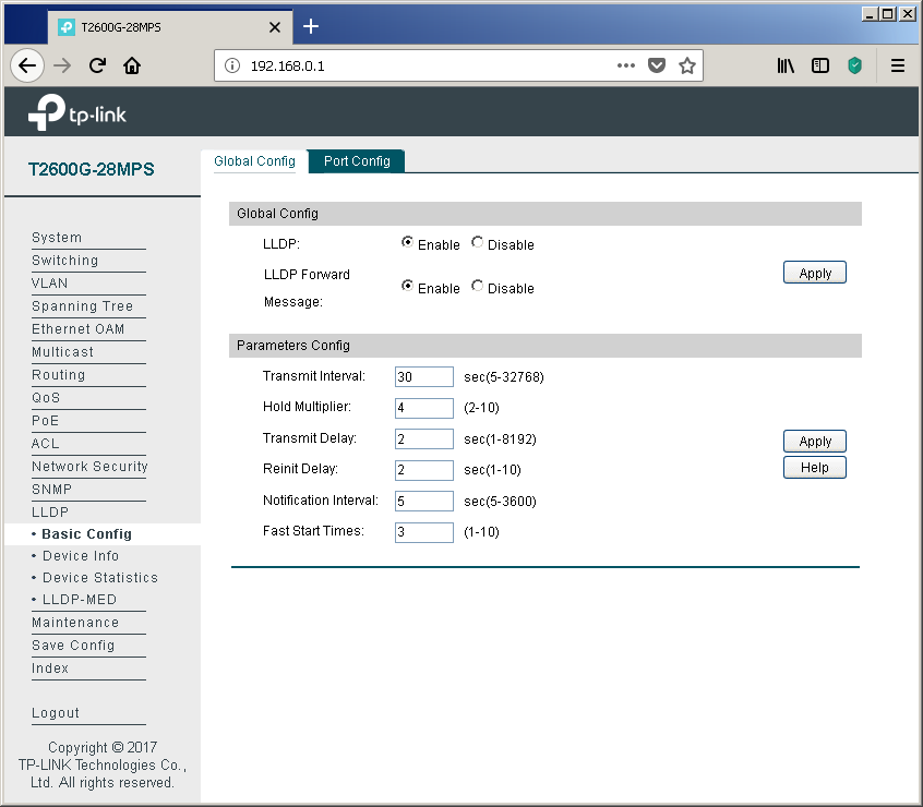
The main LLDP settings for the T2600G-28MPS switch are collected in the “Basic Config” item of the “LLDP” group of the web interface menu. Here you can configure the protocol operation both globally for the entire switch, and for each wired interface individually.

You can display the information sent and received for each of the interfaces using the “Device Info” item of the same group. We connected interface No. 20 to the switch of another vendor to show an example of information that can be viewed about equipment from other manufacturers.
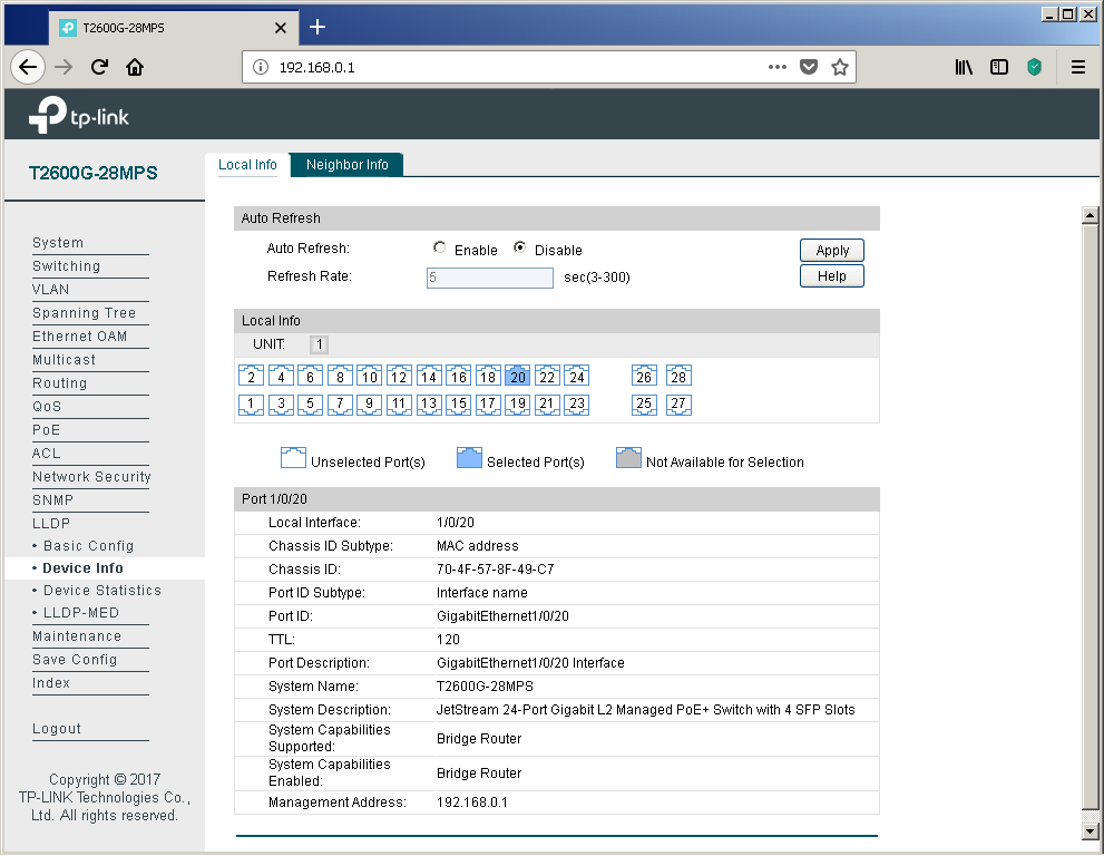
Of course, network devices from other manufacturers also correctly process information received from our switches.
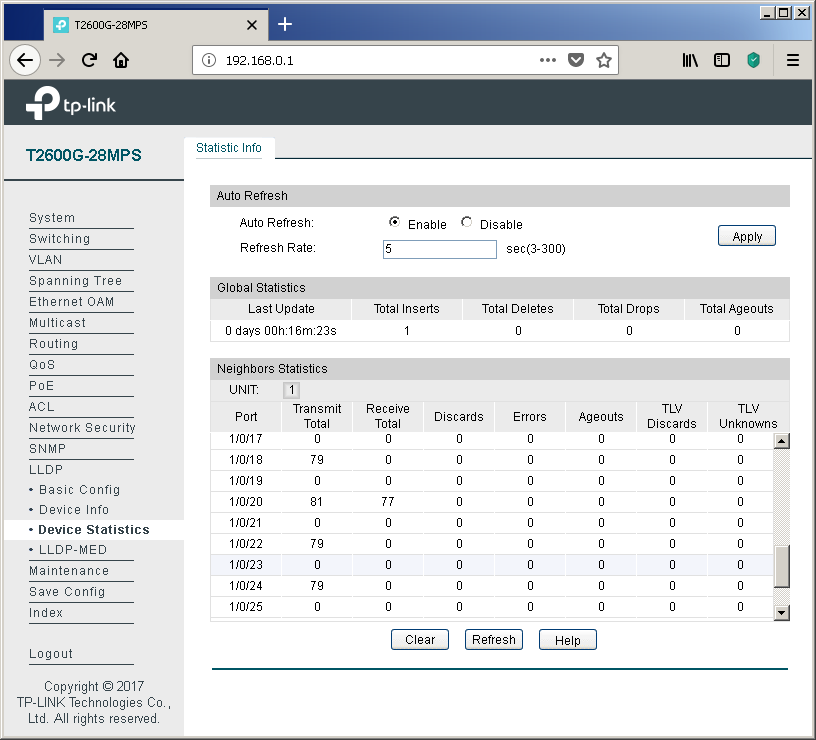
Statistics on the received and sent LLDP protocol messages are presented in the “Device Statistics” item.
Perhaps one of the main applications of the LLDP protocol in networks is the use of its extension LLDP-MED (Media Endpoint Discovery), through which service information is exchanged with voice terminal equipment. Of course, the “voice”, as before, is encapsulated in RTP; one of two protocols is traditionally used for signaling: SIP or H.323. So why do you need LLDP-MED? This extension can significantly reduce the cost of configuring IP phones and voice gateways. Typically, a separate virtual network (VLAN) is created on the switches to transmit voice data. For what? There are usually two reasons: the need for security and the desire to prioritize voice traffic.
Naturally, one could simply place all the switch ports that IP phones are connected to on this virtual network, however, network administrators often have to deal with a lack of network interfaces on the switching equipment. A very simplified example of connecting IP phones to the network with a sufficient number of free interfaces on the switch is presented below.
The problem of the lack of L2 ports on switches on campuses is often solved by connecting a user's computer to a special port on the phone. The IP phone itself has an integrated Ethernet switch with three ports: one internal and two external (for connecting to network equipment and the user's PC). Since data from two virtual networks is transmitted through the channel between the phone and the network switch (user data in access-vlan and voice data in voice-vlan), it is necessary to tag frames, for example, using 802.1q. Such tagging is a very typical solution and does not cause difficulties for network administrators. However, in order for it to run correctly,

And so EVERY phone should be configured. The process is not fast at all, agree. It is for solving this routine task that the LLDP-MED extension is used, which allows the switch to notify the IP phone of the used virtual network numbers.
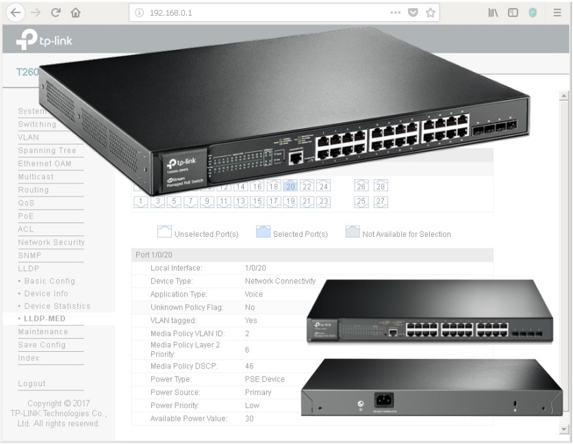
To configure the LLDP-MED extension, refer to the menu item of the same name.

Traditionally, each port can be configured individually.
Using the “Local Info” tab, you can view the information transmitted by the switch towards the connected equipment.
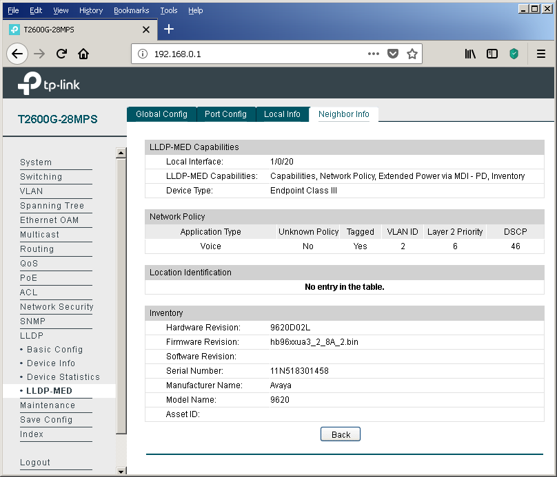
If the neighboring device supports LLDP-MED, then information about it will be displayed in the "Neighbor Info" tab.
Of course, the LLDP protocol operation parameters can also be controlled using the command line.
It would seem that the configuration can be completed on this. However, we would like to show a little more detail on how the phone and the switch interact with each other. We will explain on the example of our test model - Avaya IP Deskphone 9620L. In order not to simplify our life, we will consider the situation of a shortage of network interfaces on the switches, that is, when the user's PC is connected via telephone. We created two virtual networks (VLAN 2 - voice, VLAN3 - data), configured the corresponding virtual SVI interfaces (VLAN 2 - 192.168.2.1/24, VLAN 3 - 192.168.3.1/24) and configured two pools for the DHCP server.
Immediately upon connecting such a phone, the switch detects a powered PoE device (PD - Powered Device) and supplies voltage to the port, which allows the IP phone to turn on and start downloading. As you can see from the screenshot below, the phone is not at all gluttonous (according to the manufacturer, this model in the worst case can consume up to 5.3 watts). In principle, the maximum power consumption of almost all Avaya IP phone models does not exceed 7 watts. Other vendors have a similar situation. Consequently, the TP-Link T2600G-28MPS will provide power to 24 IP phones with a margin.
But back to LLDP. The switch saw a neighbor on this protocol. At first glance, the conclusion presented on this page looks a little strange - two entries about only one telephone. Let's try to figure out why this happens.
We see that the phone tells the switch two different Chassis IDs. In fact, this is the IP address received by the phone from the DHCP server, that is, the phone requests one address from each pool. However, the DHCP server displays only one address that was issued towards the telephone.
At this stage, everything seems completely confusing and incomprehensible. But the answer is extremely simple. One has only to consider the procedure for negotiating parameters via the LLDP protocol between the telephone and the switch.
When the phone has received power and is loading for the first time, it still does not know which virtual networks are being used, that is, there is still no information about which VID tags to mark frames. At this point, the IP phone sends untagged frames. These frames fall into the virtual network defined by the PVID field on the “Port Config” tab of the “802.1Q VLAN” item of the “VLAN” group of the menu.

That is why a record appears in the bridge bridge table about the MAC address of the phone for the virtual network, which we planned to use to transmit user data.
At this point, the phone uses the DHCP protocol to obtain an IP address and other network parameters. In parallel with this process, LLDP messaging (including LLDP-MED) occurs, as a result of which the phone recognizes the number of the virtual network into which it should place its own frames.
After finding out the number of the correct virtual network, the IP phone releases the previously received DHCP address and repeats the same process, but already tagging its own frames, which leads to obtaining the IP address and other network information already in the new virtual network. That is why we see only one leased by DHCP address. Well, and the entry in the bridge table will “hang out” until its lifetime expires (option “Aging time” tab “Dynamic Address” of the item “MAC Address” of the group “Switching” of the web interface menu). To confirm our words, we decided to bring a small piece of the dump containing the described actions.
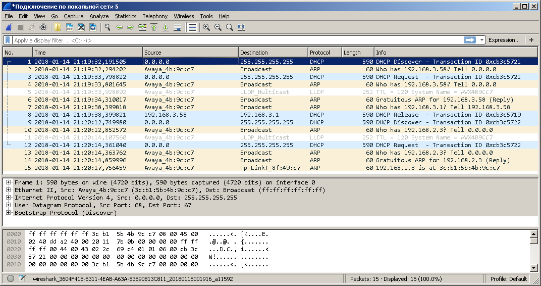
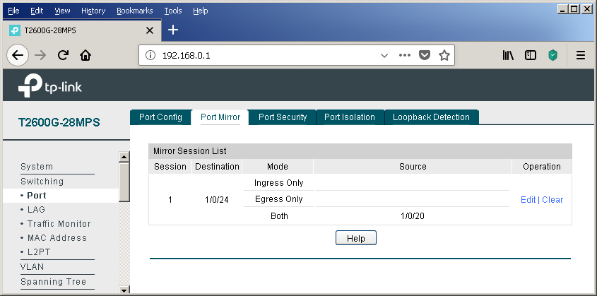
The dump was removed using the port mirroring function. Unfortunately, not all service frames can be transferred using this option.
In conclusion, I would like to note that there are several ways to tell IP phones the address of a station or voice gateway / server. If you do not consider the static indication of the address in the settings of the telephone itself and various proprietary solutions, there are not many options. These include, for example, a very obvious way to transfer this setting (along with a host of other parameters) by using a configuration file that can be downloaded by the phone via TFTP / FTP / HTTP / HTTPS. A slightly less obvious way is to use a variety of DHCP options. For example, Avaya IP phones use option # 176 to specify the address of a device that performs the functions of the H323 Gatekeeper. You can plunge into the world of the DHCP protocol with the help of the following article (http://foxnetwork.ru/index.php/component/content/article/207-dhcp.html ). In addition to the above methods of informing the phone about the gateway address, you can use another one - the LLDP protocol. To date, our switches can not yet boast support for the last two features.
Are there any other ways to simplify life for network administrators that connect computers and phones to campus networks? The answer to this question is yes. Details in the next section.
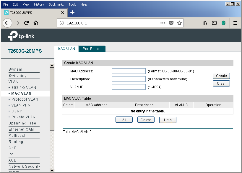
In modern networks, the frame belongs to a particular virtual network is determined either on the basis of the interface through which the frame was received by the switch (port-based VLAN), or on the basis of the protocol tag 802.1q (tag-based VLAN). There are several more ways to determine if a frame belongs to a virtual network, for example, based on the sender's MAC address. The MAC address on an Ethernet network is 48 bits long and consists of two equal parts, the first of which contains an OUI - Organizationally Unique Identifier, assigned by IEEE centrally to each network equipment manufacturer. Based on the OUI value in the sender address, the frame can be assigned by the switch to the voice virtual network. Let's go through the whole process of setting up a voice virtual network based on OUI from start to finish. In fairness it’s worth noting that our switches can determine the membership of a virtual network based on the MAC address of the device, not only for IP phones. The corresponding setting is available in the “MAC VLAN” item of the “VLAN” group of the menu.
So, you should start by managing the OUI values, on the basis of which the frames will fall into the voice virtual network. This is done using the OUI Config tab of the same menu item.

Then you need to create a virtual network for voice traffic, if for some reason it has not yet been created. You can perform this procedure using the “802.1Q VLAN” item in the “VLAN” group of the web interface menu. Add any switch interfaces at this stage to this virtual network.
After the usual virtual network has been created, it is necessary to indicate what exactly we plan to use it for the transmission of voice traffic. Only one voice virtual network can be created on our switches. The corresponding setting is available in the Global Config tab of the Voice VLAN item of the QOS group.
The final touch is to configure the physical interfaces using the Port Config tab.
It is impossible not to mention the possibility of enabling additional protection using the “Security Mode” option. When this function is enabled, the switch will not pass frames into the voice virtual network whose sender is not in the list of configured OUIs.
Of course, we could not ignore console access fans.
This, perhaps, will end with a discussion of the details of the functioning of the voice virtual network in TP-Link switches using the example of the T2600G-28MPS model.
Using the L2 + example of the TP-Link T2600G-28MPS switch, we examined useful options that make life easier for the network administrator by simplifying the implementation of some routine procedures. For example, centralized power management provides rich opportunities to control energy efficiency, allowing you to carry out a number of optimization measures. And this is not to mention the increase in the quality of the energy supply of the terminal equipment itself.
Have you created a new department? Have you expanded the staff? Hired many new employees at once? And everyone needs phones, and the ports on the switches are sorely lacking? Using the DHCP and LLDP protocols, as well as the Voice VLAN option, the network administrator will not feel much difference between connecting one new employee or as many as hundreds without wasting the switch ports for nothing.
Let's allow ourselves one more reminder - save the config after each significant change. The process, of course, is not automatic, but it will save a lot of effort and time after the next “oops”.
We do not set ourselves the goal of providing a complete description of all the features of the T2600G-28MPS model, instead we will focus on those functions on which the operation of supported wireless networks and IP-telephony directly depends.
Setting up and working with Power over Ethernet
Providing power to terminal equipment is not the easiest task to be solved by network engineers. Of course, you can use external power supplies that come with most models of access points, IP cameras and phones. However, this solution is not scalable, and it is difficult to attribute it to a convenient one: a large number of additional blocks and wires, increased network deployment time, deterioration of the appearance of premises, the impossibility of centralized power management, the inability to guarantee the quality of power, and so on. Instead, an increasing number of network administrators are turning their attention to PoE technology, which allows you to immediately solve all of these problems.
TP-Link T2600G-28MPS has an increased energy budget (up to 384 watts). Today, two IEEE standards are widely used that describe the operation of the technology: 802.3af-2003 and 802.3at-2009. The first of them determines the maximum available power equal to 15.4 watts. The maximum power provided by the second is 30 watts. Simple arithmetic shows that this switch allows you to simultaneously provide power to 802.3af consumers connected to all ports of the device. When connecting more powerful consumers (with support for the 802.3at standard) at the same time, it will not be possible to provide the maximum allowable power to all terminal devices, however, it should be noted that not all 802.3at devices constantly require 25.5 watts of electricity to operate. Such consumption will be rather, an exception, or may be required for a relatively short period of time. In addition, the switch has settings that allow you to resolve the situation in the mode of energy budget deficit. Let's see what the network administrator can manage.
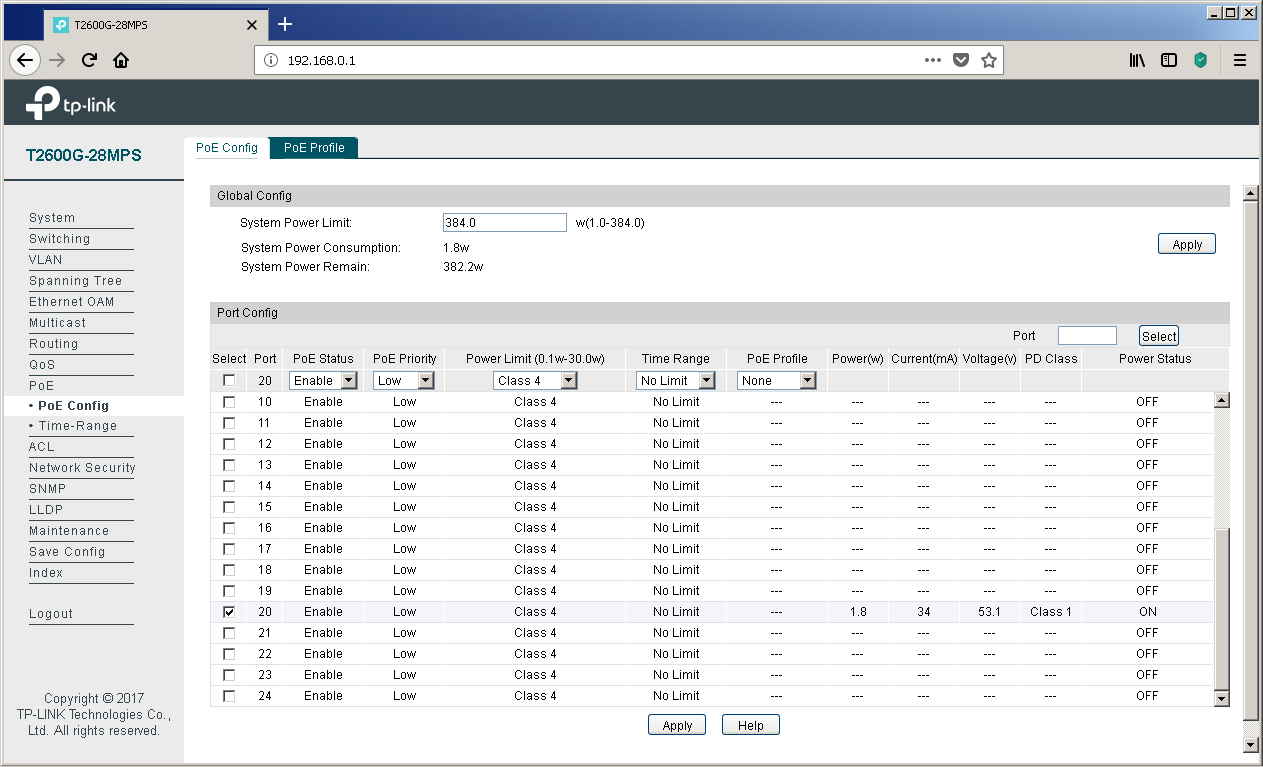
All settings related to PoE technology are collected in the same menu group of the web interface. Using the “PoE Config” item, the administrator can specify the maximum power consumed by the switch to power PoE clients, view and change the current state of the ports, set the interface priority and the class of the connected device, select the time interval and PoE profile.
It can be seen from the above screenshot that some devices are connected to ports No. 20 and 22, currently consuming 3.6 watts of electricity each (current - 69 mA and voltage 53.1 V), which corresponds to the fourth class of PoE. We will not make intrigue out of these powered devices - these are our access points of the CAP1200 model .
The PoE Profile tab of the same menu item allows you to create energy profiles, which greatly simplifies the configuration of the switch when connecting typical consumers.
Administrators who prefer to work on the command line can also control power through PoE using the power command group.
T2600G-28MPS(config)#show power inline configuration interface
Interface  PoE-Status PoE-Prio Power-Limit(w) Time-Range       PoE-Profile
---------- ---------- -------- -------------- ---------------- ----------------
 Gi1/0/1   Enable     Low      Class4         No Limit         None
 Gi1/0/2   Enable     Low      Class4         No Limit         None
 Gi1/0/3   Enable     Low      Class4         No Limit         None
 Gi1/0/4   Enable     Low      Class4         No Limit         None
 Gi1/0/5   Enable     Low      Class4         No Limit         None
 Gi1/0/6   Enable     Low      Class4         No Limit         None
 Gi1/0/7   Enable     Low      Class4         No Limit         None
 Gi1/0/8   Enable     Low      Class4         No Limit         None
 Gi1/0/9   Enable     Low      Class4         No Limit         None
 Gi1/0/10  Enable     Low      Class4         No Limit         None
 Gi1/0/11  Enable     Low      Class4         No Limit         None
 Gi1/0/12  Enable     Low      Class4         No Limit         None
 Gi1/0/13  Enable     Low      Class4         No Limit         None
 Gi1/0/14  Enable     Low      Class4         No Limit         None
 Gi1/0/15  Enable     Low      Class4         No Limit         None
 Gi1/0/16  Enable     Low      Class4         No Limit         None
 Gi1/0/17  Enable     Low      Class4         No Limit         None
 Gi1/0/18  Enable     Low      Class4         No Limit         None
 Gi1/0/19  Enable     Low      Class4         No Limit         None
 Gi1/0/20  Enable     Low      Class4         No Limit         None
 Gi1/0/21  Enable     Low      Class4         No Limit         None
 Gi1/0/22  Enable     Low      Class4         No Limit         None
 Gi1/0/23  Enable     Low      Class4         No Limit         None
 Gi1/0/24  Enable     Low      Class4         No Limit         None
T2600G-28MPS(config)#show power inline in
T2600G-28MPS(config)#show power inline information
information
T2600G-28MPS(config)#show power inline information interface
interface
T2600G-28MPS(config)#show power inline information interface
Interface  Power(w)  Current(mA)  Voltage(v)  PD-Class  Power-Status
---------- --------  -----------  ----------  --------  ----------------
 Gi1/0/1   0.0       0            0.0         N/A       OFF
 Gi1/0/2   0.0       0            0.0         N/A       OFF
 Gi1/0/3   0.0       0            0.0         N/A       OFF
 Gi1/0/4   0.0       0            0.0         N/A       OFF
 Gi1/0/5   0.0       0            0.0         N/A       OFF
 Gi1/0/6   0.0       0            0.0         N/A       OFF
 Gi1/0/7   0.0       0            0.0         N/A       OFF
 Gi1/0/8   0.0       0            0.0         N/A       OFF
 Gi1/0/9   0.0       0            0.0         N/A       OFF
 Gi1/0/10  0.0       0            0.0         N/A       OFF
 Gi1/0/11  0.0       0            0.0         N/A       OFF
 Gi1/0/12  0.0       0            0.0         N/A       OFF
 Gi1/0/13  0.0       0            0.0         N/A       OFF
 Gi1/0/14  0.0       0            0.0         N/A       OFF
 Gi1/0/15  0.0       0            0.0         N/A       OFF
 Gi1/0/16  0.0       0            0.0         N/A       OFF
 Gi1/0/17  0.0       0            0.0         N/A       OFF
 Gi1/0/18  0.0       0            0.0         N/A       OFF
 Gi1/0/19  0.0       0            0.0         N/A       OFF
 Gi1/0/20  3.6       69          53.1         Class4   ON
 Gi1/0/21  0.0       0            0.0         N/A       OFF
 Gi1/0/22  3.6       69          52.8        Class 4   ON
 Gi1/0/23  0.0       0            0.0         N/A       OFF
 Gi1/0/24  0.0       0            0.0         N/A       OFF
T2600G-28MPS(config)#show power
 holiday              - Display holiday configuration
 inline               - Display power inline configuration
 profile              - Display power inline profile configuration
 time-range           - Display time segment configuration
T2600G-28MPS(config)#show power inline
inline
T2600G-28MPS(config)#show power inline
 configuration        - Display power inline configuration
 information          - Display power inline information

T2600G-28MPS(config)#power
 holiday              - Add or delete a holiday
 inline               - Power Inline Configuration
 profile              - Add or delete a profile
 time-range           - Define the time range entries
T2600G-28MPS(config)#power inline
inline
T2600G-28MPS(config)#power inline
 consumption          - Set the global power limit
T2600G-28MPS(config)#power profile
profile
T2600G-28MPS(config)#power profile
                - Profile name, the length is 1-16
Very often, company executives try to reduce electricity bills, which accountants have to pay monthly. The “Time-Range” item in the same menu group can help them with this. Using this item, the administrator can create a schedule in accordance with which consumers will be catering. So, for example, at night and on weekends, the number of employees present at their workplaces is usually much less than during the so-called business hours. Reducing the number of users leads to a reduction in the load on the network infrastructure - access points will work almost idle. Automatic shutdown of some of them will not affect the level of service provided, as wireless users will be automatically redistributed between the remaining enabled access points. On Monday morning, the backup equipment will be automatically turned on again on schedule, thus preparing everything necessary for the return of our network administrator's colleagues to the office. The process of switching on multiple access points will be routinely processed by a wireless controller, the frequency and radiation power will be redistributed so as to provide the best coverage throughout the territory.
Sometimes PoE devices are installed on sensitive objects, which are strictly prohibited during off-hours. In this case, it will be possible to prevent even more money from being wasted by disabling IP-phones of some employees.
The power schedule is controlled using the “Time-Range” item.
Calculate how much you could save for the New Year holidays this year! And ahead of us is still a great weekend in May.
LLDP
Link Layer Discovery Protocol (IEEE 802.1ab) - a protocol that allows you to detect neighboring devices, as well as tell neighbors certain information about themselves.
The main LLDP settings for the T2600G-28MPS switch are collected in the “Basic Config” item of the “LLDP” group of the web interface menu. Here you can configure the protocol operation both globally for the entire switch, and for each wired interface individually.
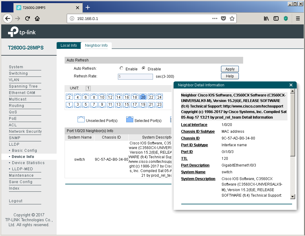
You can display the information sent and received for each of the interfaces using the “Device Info” item of the same group. We connected interface No. 20 to the switch of another vendor to show an example of information that can be viewed about equipment from other manufacturers.
Of course, network devices from other manufacturers also correctly process information received from our switches.
switch#sho lldp ne de
------------------------------------------------
Local Intf: Gi1/0/3
Chassis id: 704f.578f.49c7
Port id: GigabitEthernet1/0/20
Port Description: GigabitEthernet1/0/20 Interface
System Name: T2600G-28MPS
System Description:
JetStream 24-Port Gigabit L2 Managed PoE+ Switch with 4 SFP Slots
Time remaining: 93 seconds
System Capabilities: B,R
Enabled Capabilities: B,R
Management Addresses:
    IP: 192.168.0.1
Auto Negotiation - supported, enabled
Physical media capabilities:
    1000baseT(FD)
    1000baseT(HD)
    1000baseX(FD)
    1000baseX(HD)
    Symm Pause(FD)
    Asym Pause(FD)
    100base-TX(FD)
    100base-TX(HD)
    10base-T(FD)
    10base-T(HD)
    Other/unknown
Media Attachment Unit type: 30
Vlan ID: 1
Total entries displayed: 1
Statistics on the received and sent LLDP protocol messages are presented in the “Device Statistics” item.
Perhaps one of the main applications of the LLDP protocol in networks is the use of its extension LLDP-MED (Media Endpoint Discovery), through which service information is exchanged with voice terminal equipment. Of course, the “voice”, as before, is encapsulated in RTP; one of two protocols is traditionally used for signaling: SIP or H.323. So why do you need LLDP-MED? This extension can significantly reduce the cost of configuring IP phones and voice gateways. Typically, a separate virtual network (VLAN) is created on the switches to transmit voice data. For what? There are usually two reasons: the need for security and the desire to prioritize voice traffic.
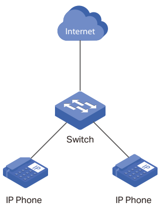
Naturally, one could simply place all the switch ports that IP phones are connected to on this virtual network, however, network administrators often have to deal with a lack of network interfaces on the switching equipment. A very simplified example of connecting IP phones to the network with a sufficient number of free interfaces on the switch is presented below.
The problem of the lack of L2 ports on switches on campuses is often solved by connecting a user's computer to a special port on the phone. The IP phone itself has an integrated Ethernet switch with three ports: one internal and two external (for connecting to network equipment and the user's PC). Since data from two virtual networks is transmitted through the channel between the phone and the network switch (user data in access-vlan and voice data in voice-vlan), it is necessary to tag frames, for example, using 802.1q. Such tagging is a very typical solution and does not cause difficulties for network administrators. However, in order for it to run correctly,
And so EVERY phone should be configured. The process is not fast at all, agree. It is for solving this routine task that the LLDP-MED extension is used, which allows the switch to notify the IP phone of the used virtual network numbers.
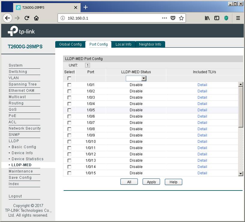
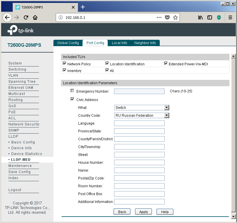
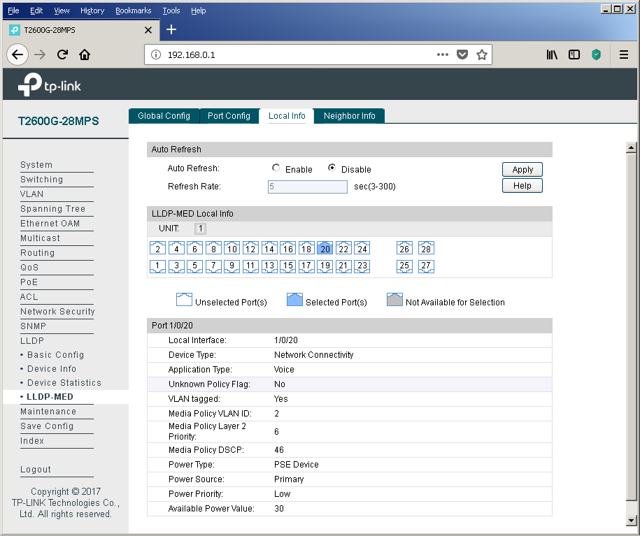
To configure the LLDP-MED extension, refer to the menu item of the same name.
Traditionally, each port can be configured individually.
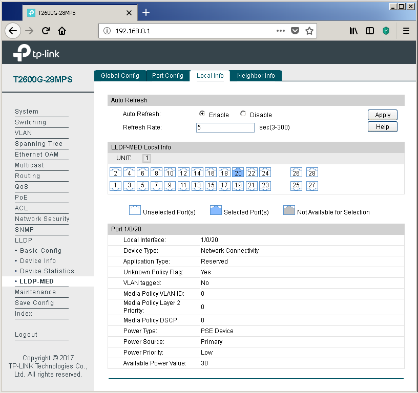
Using the “Local Info” tab, you can view the information transmitted by the switch towards the connected equipment.
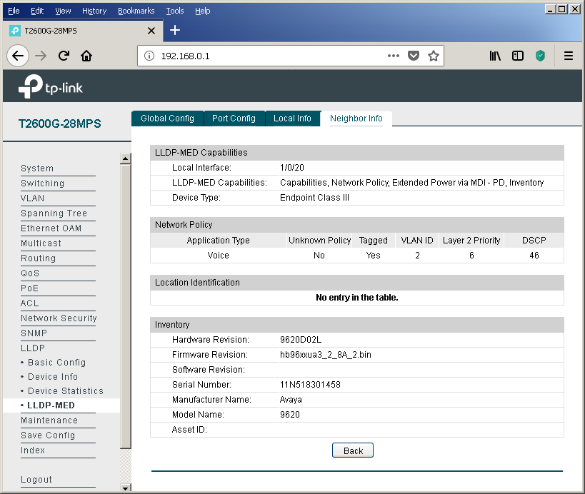
If the neighboring device supports LLDP-MED, then information about it will be displayed in the "Neighbor Info" tab.
Of course, the LLDP protocol operation parameters can also be controlled using the command line.
T2600G-28MPS(config)#sho lld
 LLDP Status:                  Enabled
 LLDP Forward Message:         Enabled
 Tx Interval:                  30 seconds
 TTL Multiplier:               4
 Tx Delay:                     2 seconds
 Initialization Delay:         2 seconds
 Trap Notification Interval:   5 seconds
 Fast-packet Count:            3
 LLDP-MED Fast Start Repeat Count:  4
T2600G-28MPS(config)#sho lld neighbor-information interface
LLDP Neighbor Information:
gigabitEthernet 1/0/20:
Neighbor index 1:
        Chassis type:                           MAC address
        Chassis ID:                             9C:57:AD:B0:34:80
        Port ID type:                           Interface name
        Port ID:                                Gi1/0/3
        Port description:                       GigabitEthernet1/0/3
        TTL:                                    120
        System name:                            switch
        System description:                     Cisco IOS Software, C3560CX Soft
                                                ware (C3560CX-UNIVERSALK9-M), Ve
                                                rsion 15.2(6)E, RELEASE SOFTWARE
                                                 (fc4)
                                                Technical Support: http://www.ci
                                                sco.com/techsupport
                                                Copyright (c) 1986-2017 by Cisco
                                                 Systems, Inc.
                                                Compiled Sat 05-Aug-17 13:21 by
                                                prod_rel_team
        System capabilities supported:          Bridge Router
        System capabilities enabled:            Bridge Router
        Management address type:                ipv4
        Management address:                     192.168.1.10
        Management address interface type:      System Port Number
        Management address interface ID:        1
        Management address OID:                 0
        Port VLAN ID(PVID):                     1
        Port and protocol VLAN ID(PPVID):
        Port and protocol VLAN supported:
        Port and protocol VLAN enabled:
        Protocol identity:
        Auto-negotiation supported:             Yes
        Auto-negotiation enabled:               Yes
        OperMau:                                speed(1000)/duplex(Full)
        Link aggregation supported:
        Link aggregation enabled:
        Aggregation port ID:
        Power port class:
        PSE power supported:
        PSE power enabled:
        PSE pairs control ability:
        Maximum frame size:
T2600G-28MPS(config)#lldp
 forward_message      - Enable/Disable LLDP message forwarding when LLDP
                         Global state is Disable.
 hold-multiplier      - Configure LLDP TTL multiplier
 med-fast-count       - Configure LLDP-MED fast mechanism repeat count
 timer                - Configure LLDP timer

T2600G-28MPS(config)#lldp med-fast-count
med-fast-count
T2600G-28MPS(config)#lldp med-fast-count
 <1-10>               - Fast mechanism repeat count number
It would seem that the configuration can be completed on this. However, we would like to show a little more detail on how the phone and the switch interact with each other. We will explain on the example of our test model - Avaya IP Deskphone 9620L. In order not to simplify our life, we will consider the situation of a shortage of network interfaces on the switches, that is, when the user's PC is connected via telephone. We created two virtual networks (VLAN 2 - voice, VLAN3 - data), configured the corresponding virtual SVI interfaces (VLAN 2 - 192.168.2.1/24, VLAN 3 - 192.168.3.1/24) and configured two pools for the DHCP server.
Immediately upon connecting such a phone, the switch detects a powered PoE device (PD - Powered Device) and supplies voltage to the port, which allows the IP phone to turn on and start downloading. As you can see from the screenshot below, the phone is not at all gluttonous (according to the manufacturer, this model in the worst case can consume up to 5.3 watts). In principle, the maximum power consumption of almost all Avaya IP phone models does not exceed 7 watts. Other vendors have a similar situation. Consequently, the TP-Link T2600G-28MPS will provide power to 24 IP phones with a margin.
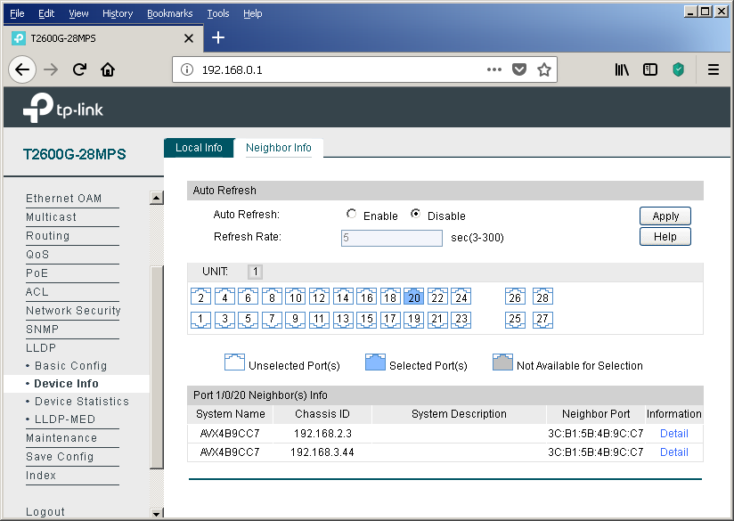
But back to LLDP. The switch saw a neighbor on this protocol. At first glance, the conclusion presented on this page looks a little strange - two entries about only one telephone. Let's try to figure out why this happens.
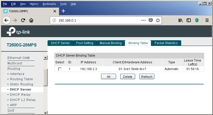
We see that the phone tells the switch two different Chassis IDs. In fact, this is the IP address received by the phone from the DHCP server, that is, the phone requests one address from each pool. However, the DHCP server displays only one address that was issued towards the telephone.
At this stage, everything seems completely confusing and incomprehensible. But the answer is extremely simple. One has only to consider the procedure for negotiating parameters via the LLDP protocol between the telephone and the switch.
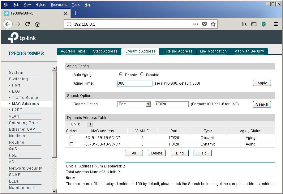
When the phone has received power and is loading for the first time, it still does not know which virtual networks are being used, that is, there is still no information about which VID tags to mark frames. At this point, the IP phone sends untagged frames. These frames fall into the virtual network defined by the PVID field on the “Port Config” tab of the “802.1Q VLAN” item of the “VLAN” group of the menu.
That is why a record appears in the bridge bridge table about the MAC address of the phone for the virtual network, which we planned to use to transmit user data.
At this point, the phone uses the DHCP protocol to obtain an IP address and other network parameters. In parallel with this process, LLDP messaging (including LLDP-MED) occurs, as a result of which the phone recognizes the number of the virtual network into which it should place its own frames.
After finding out the number of the correct virtual network, the IP phone releases the previously received DHCP address and repeats the same process, but already tagging its own frames, which leads to obtaining the IP address and other network information already in the new virtual network. That is why we see only one leased by DHCP address. Well, and the entry in the bridge table will “hang out” until its lifetime expires (option “Aging time” tab “Dynamic Address” of the item “MAC Address” of the group “Switching” of the web interface menu). To confirm our words, we decided to bring a small piece of the dump containing the described actions.
The dump was removed using the port mirroring function. Unfortunately, not all service frames can be transferred using this option.
In conclusion, I would like to note that there are several ways to tell IP phones the address of a station or voice gateway / server. If you do not consider the static indication of the address in the settings of the telephone itself and various proprietary solutions, there are not many options. These include, for example, a very obvious way to transfer this setting (along with a host of other parameters) by using a configuration file that can be downloaded by the phone via TFTP / FTP / HTTP / HTTPS. A slightly less obvious way is to use a variety of DHCP options. For example, Avaya IP phones use option # 176 to specify the address of a device that performs the functions of the H323 Gatekeeper. You can plunge into the world of the DHCP protocol with the help of the following article (http://foxnetwork.ru/index.php/component/content/article/207-dhcp.html ). In addition to the above methods of informing the phone about the gateway address, you can use another one - the LLDP protocol. To date, our switches can not yet boast support for the last two features.
Are there any other ways to simplify life for network administrators that connect computers and phones to campus networks? The answer to this question is yes. Details in the next section.
Voice VLAN
In modern networks, the frame belongs to a particular virtual network is determined either on the basis of the interface through which the frame was received by the switch (port-based VLAN), or on the basis of the protocol tag 802.1q (tag-based VLAN). There are several more ways to determine if a frame belongs to a virtual network, for example, based on the sender's MAC address. The MAC address on an Ethernet network is 48 bits long and consists of two equal parts, the first of which contains an OUI - Organizationally Unique Identifier, assigned by IEEE centrally to each network equipment manufacturer. Based on the OUI value in the sender address, the frame can be assigned by the switch to the voice virtual network. Let's go through the whole process of setting up a voice virtual network based on OUI from start to finish. In fairness it’s worth noting that our switches can determine the membership of a virtual network based on the MAC address of the device, not only for IP phones. The corresponding setting is available in the “MAC VLAN” item of the “VLAN” group of the menu.
So, you should start by managing the OUI values, on the basis of which the frames will fall into the voice virtual network. This is done using the OUI Config tab of the same menu item.
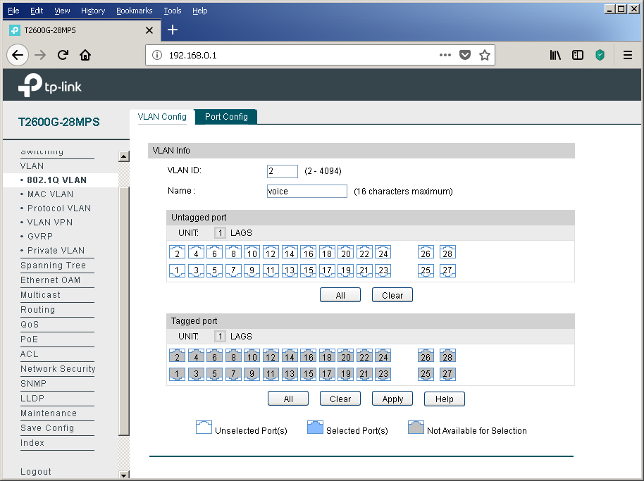
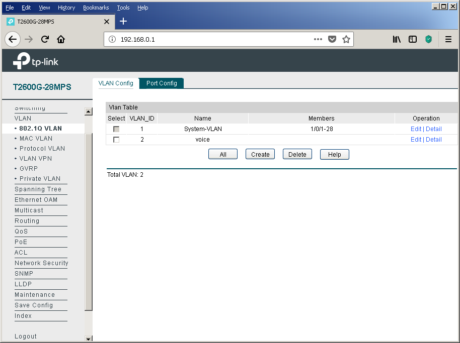
Then you need to create a virtual network for voice traffic, if for some reason it has not yet been created. You can perform this procedure using the “802.1Q VLAN” item in the “VLAN” group of the web interface menu. Add any switch interfaces at this stage to this virtual network.
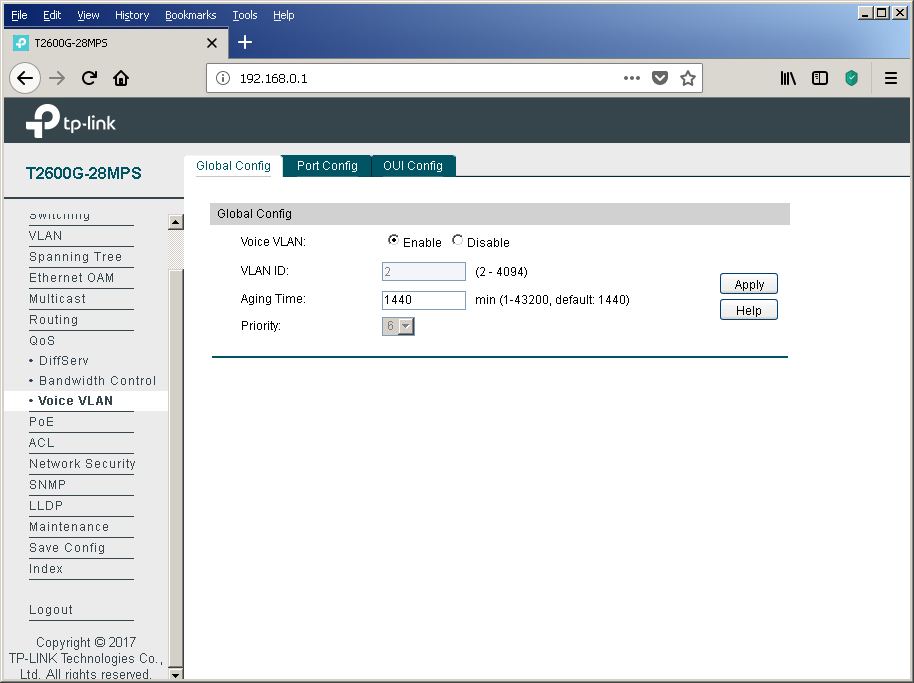
After the usual virtual network has been created, it is necessary to indicate what exactly we plan to use it for the transmission of voice traffic. Only one voice virtual network can be created on our switches. The corresponding setting is available in the Global Config tab of the Voice VLAN item of the QOS group.
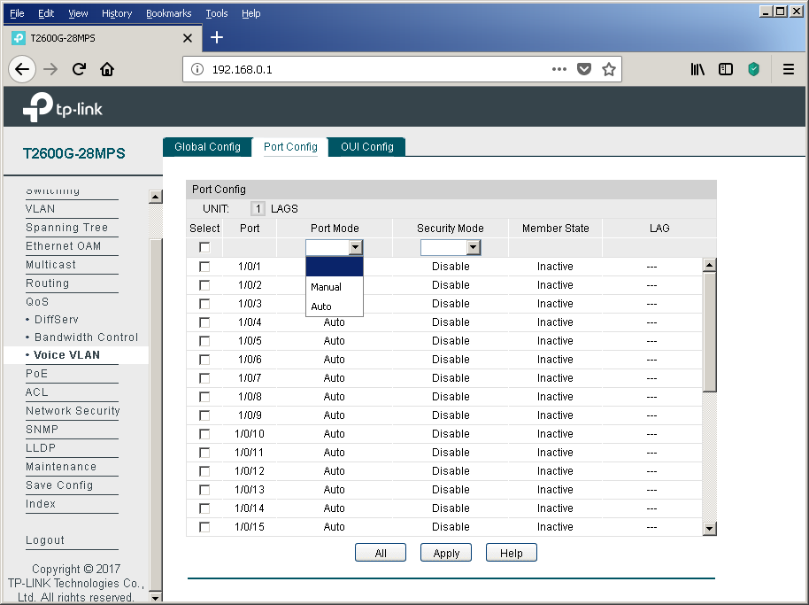
The final touch is to configure the physical interfaces using the Port Config tab.
It is impossible not to mention the possibility of enabling additional protection using the “Security Mode” option. When this function is enabled, the switch will not pass frames into the voice virtual network whose sender is not in the list of configured OUIs.
Of course, we could not ignore console access fans.
T2600G-28MPS#sho vla
VLAN  Name                 Status    Ports
----- -------------------- --------- ----------------------------------------
1     System-VLAN          active    Gi1/0/1, Gi1/0/2, Gi1/0/3, Gi1/0/4,
                                     Gi1/0/5, Gi1/0/6, Gi1/0/7, Gi1/0/8,
                                     Gi1/0/9, Gi1/0/10, Gi1/0/11, Gi1/0/12,
                                     Gi1/0/13, Gi1/0/14, Gi1/0/15, Gi1/0/16,
                                     Gi1/0/17, Gi1/0/18, Gi1/0/19, Gi1/0/20,
                                     Gi1/0/21, Gi1/0/22, Gi1/0/23, Gi1/0/24,
                                     Gi1/0/25, Gi1/0/26, Gi1/0/27, Gi1/0/28
2     voice                active
Primary Secondary Type               Ports
------- --------- ------------------ ----------------------------------------
T2600G-28MPS#sho voice vlan
 oui                  - Display voice VLAN OUI configuration
 switchport           - Display voice VLAN configuration of switchport

T2600G-28MPS#sho voice vlan
 Voice VLAN status: Enabled
 VLAN ID: 2
 Aging Time: 1440
 Voice Priority: 6
T2600G-28MPS#sho voice vlan switchport
switchport
T2600G-28MPS#sho voice vlan switchport
 Port       Auto-mode    Security     State        LAG
 ------     ------------ ------------ ------------ ------
 Gi1/0/1    Auto         Disabled     Inactive     N/A
 Gi1/0/2    Auto         Disabled     Inactive     N/A
 Gi1/0/3    Auto         Disabled     Inactive     N/A
 Gi1/0/4    Auto         Disabled     Inactive     N/A
 Gi1/0/5    Auto         Disabled     Inactive     N/A
 Gi1/0/6    Auto         Disabled     Inactive     N/A
 Gi1/0/7    Auto         Disabled     Inactive     N/A
 Gi1/0/8    Auto         Disabled     Inactive     N/A
 Gi1/0/9    Auto         Disabled     Inactive     N/A
 Gi1/0/10   Auto         Disabled     Inactive     N/A
 Gi1/0/11   Auto         Disabled     Inactive     N/A
 Gi1/0/12   Auto         Disabled     Inactive     N/A
 Gi1/0/13   Auto         Disabled     Inactive     N/A
 Gi1/0/14   Auto         Disabled     Inactive     N/A
 Gi1/0/15   Auto         Disabled     Inactive     N/A
 Gi1/0/16   Auto         Disabled     Inactive     N/A
 Gi1/0/17   Auto         Disabled     Inactive     N/A
 Gi1/0/18   Auto         Disabled     Inactive     N/A
 Gi1/0/19   Auto         Disabled     Inactive     N/A
 Gi1/0/20   Auto         Disabled     Inactive     N/A
 Gi1/0/21   Auto         Disabled     Inactive     N/A
 Gi1/0/22   Auto         Disabled     Inactive     N/A
 Gi1/0/23   Auto         Disabled     Inactive     N/A
 Gi1/0/24   Auto         Disabled     Inactive     N/A
 Gi1/0/25   Auto         Disabled     Inactive     N/A
 Gi1/0/26   Auto         Disabled     Inactive     N/A
 Gi1/0/27   Auto         Disabled     Inactive     N/A
 Gi1/0/28   Auto         Disabled     Inactive     N/A
T2600G-28MPS#sho voice vlan oui
 Index   OUI-MAC             OUI-Mask            Description
 ------- ------------------- ------------------- --------------------
 1       00:01:e3:00:00:00   ff:ff:ff:00:00:00   Siemens Phone
 2       00:03:6b:00:00:00   ff:ff:ff:00:00:00   Cisco Phone
 3       00:04:0d:00:00:00   ff:ff:ff:00:00:00   Avaya Phone
 4       00:60:b9:00:00:00   ff:ff:ff:00:00:00   Philips Phone
 5       00:d0:1e:00:00:00   ff:ff:ff:00:00:00   Pingtel Phone
 6       00:e0:75:00:00:00   ff:ff:ff:00:00:00   PolyCom Phone
 7       00:e0:bb:00:00:00   ff:ff:ff:00:00:00   3Com Phone
T2600G-28MPS#conf
T2600G-28MPS(config)#voice vlan
 <2-4094>             - Specify 802.1Q VLAN ID
 aging                - Configure voice VLAN aging time
 mac-address          - Configure OUI address
 priority             - Configure voice VLAN flow priority
T2600G-28MPS(config)#voice vlan
This, perhaps, will end with a discussion of the details of the functioning of the voice virtual network in TP-Link switches using the example of the T2600G-28MPS model.
To summarize
Using the L2 + example of the TP-Link T2600G-28MPS switch, we examined useful options that make life easier for the network administrator by simplifying the implementation of some routine procedures. For example, centralized power management provides rich opportunities to control energy efficiency, allowing you to carry out a number of optimization measures. And this is not to mention the increase in the quality of the energy supply of the terminal equipment itself.
Have you created a new department? Have you expanded the staff? Hired many new employees at once? And everyone needs phones, and the ports on the switches are sorely lacking? Using the DHCP and LLDP protocols, as well as the Voice VLAN option, the network administrator will not feel much difference between connecting one new employee or as many as hundreds without wasting the switch ports for nothing.
Let's allow ourselves one more reminder - save the config after each significant change. The process, of course, is not automatic, but it will save a lot of effort and time after the next “oops”.