Pi-Sonos: a hobby out of control

The idea of the design of the new building of the Internet radio station Pi-Sonos was born before the completion of the previous version. Over time, she absorbed the accumulated user experience and took into account previously admitted shortcomings. This time everything is “grown-up”.
Please love and respect
Let's say goodbye with the name " Pi-Sonos ", and today we will continue to call the column " RadioBox ". And although this time Sonos Play 1 had the greatest impact on the development of the project, the new name, firstly, sounds better, and secondly, reflects its specificity and independence.
Motivation
It seems to be the case number 2 was more user-friendly compared with the first , but he, too, was not without flaws.
The main and principal were two of them:
- The “play / pause”
button on the front end. The button is not the toughest, but nevertheless, when you click on it, the column very often shifted. - Analog volume control (“twist”) The
volume can be adjusted not only from the smartphone, but also on the speaker itself. The first method is digital, the second is analog. Accordingly, intermittently appeared between them. It was especially frustrating cases when someone twisted the analog volume to 0, and then no matter how much you poked into the smartphone, you could not do it louder, you had to get up anyway and go turn the knob.
Consequently, it was necessary at least to replace the analog twist with two numeric volume buttons, and move all three buttons to the upper end. By the way, in Sonos Play 1 it is done that way.
Here are added two more Wishlist. The first is the smooth flashing of the LED in pause mode. The second is a different color of the LED during the loading of the column, so that without a smartphone it is clear when the column is ready for use after switching on.
And last but not least - I wanted a beautiful case with a minimum number of seams, smooth lines and a stylish design. I wanted to repeat the aesthetics and conciseness of Sonos.
Process
Case The
sketch at the beginning of the article is a real sketch of the future case. Phase-inverters are not traced there, but the volume of the case is already calculated for the existing speakers and the places for the speakers and electronic filling are allocated. Smoothed corners are a real challenge for me. Whatever one may say, it’s impossible to glue this from individual walls out of 8mm MDF ( I do not consider other materials for two reasons: 1) the ease of processing this MDF; 2) the absence of other normal materials in stores in my area ). I had to completely change the approach to the manufacture of the body.
This time it was necessary to apply the technology of gluing layers. It is simple to indecency: we dissect the entire body with horizontal planes with an interval of 8 mm and cut out the resulting projections from MDF. The mastermind of technology, as always, the channelSoundBlab . The main advantage of this approach is that you can immediately make a lot of cameras of almost any shape (for example, phase shifters are very convenient to do). But as you know, the devil is in the details.
The height of the case with all the “covers” is 168mm, MDF is 8mm thick, i.e. need to make 21 layer. No not like this. It is necessary:
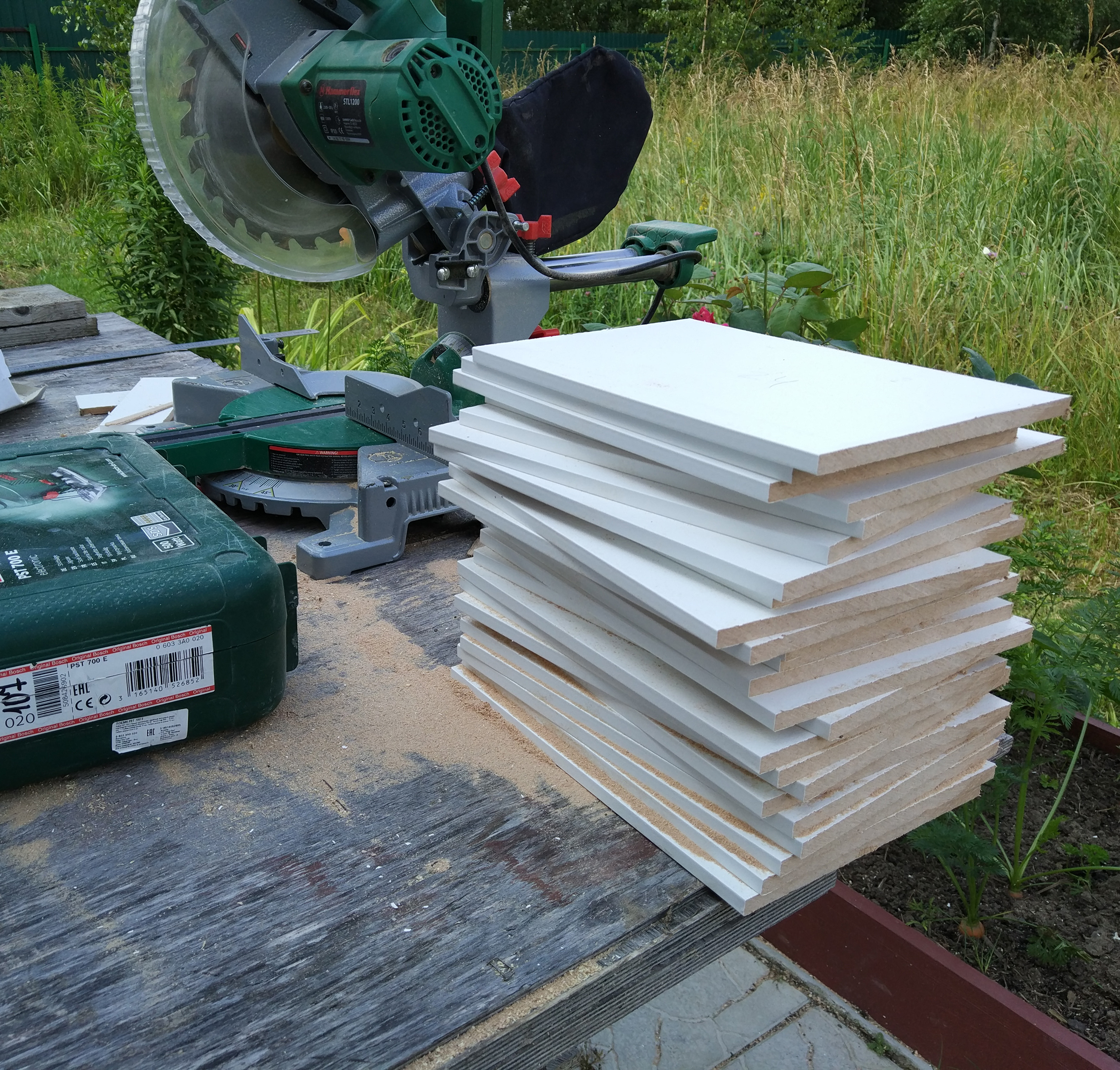
- sawed MDF panels into 21 blanks;
- then make 21 parts of a certain size (i.e., milling 63 faces, 3 faces on each part, one face was initially flat, and therefore starting);
- then cut with a mill with 84 angles according to the template;
- next - cut about 50 holes of different size and shape;
- then glue all the parts into a single case;
- and drill and drill holes for the speakers and ports of the Raspberry Pi;
- finally, putty, sanding and painting the case and covers;
- and only then can one calmly proceed to the assembly of the components inside the case and the "finishing" finishing of the column.
If there were no problems with the saw (on the miter saw of claim 1, it took about 10 minutes), then some difficulties started. For those who do not encounter wood processing, I will explain: to make more than 2 strictly rectangular parts of exactly the same size and shape using only a milling cutter and a ruler is very difficult.
It was possible to make one detail, and then use it as a template (something like this ), but then (as you can see by example) you can only process 2 faces out of 3x at a time, and then you need to rotate the workpiece, which still threatened to "knock down the sight" and do something crooked.
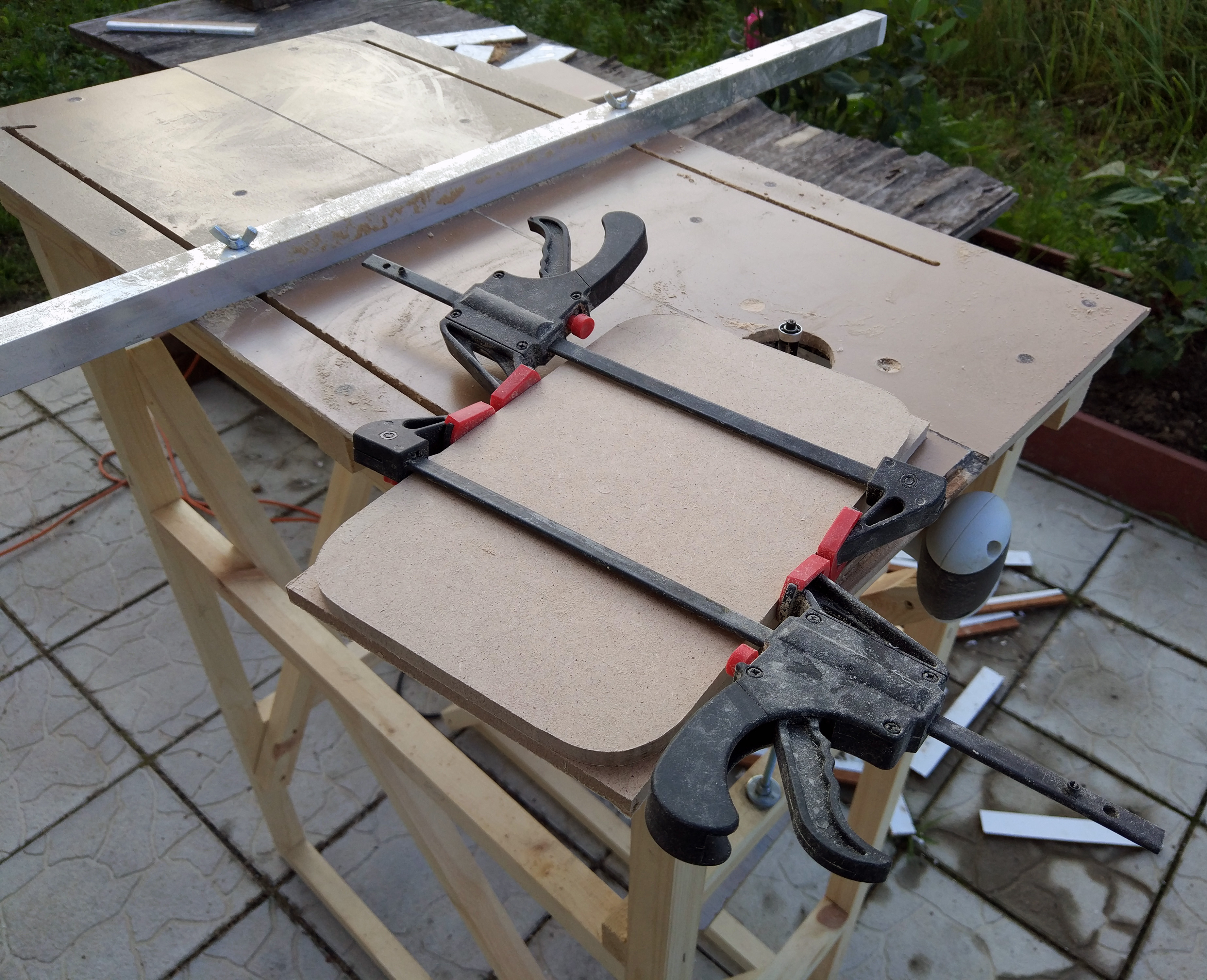
In practice, it turned out to be easier and better to assemble your own small milling table and mill the parts already on it.
A little about the table for those who are curious
В сборке фрезерного стола нет ничего сложного. Материалом столешницы послужили остатки ламината — он достаточно жесткий и дает идеально ровно гладкую поверхность. Для рамы использован строганный брусок 30х30мм. 2 рамы, 4 с небольшим ребра жесткости — et… voilà:
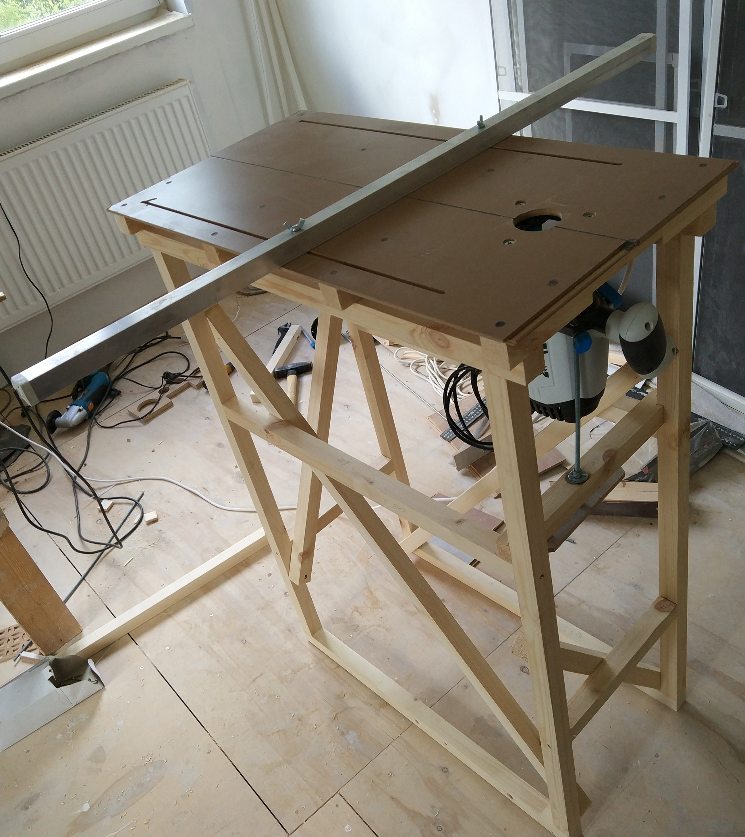
В качестве направляющей для фрезеровки идеально подходит квадратный алюминиевый профиль 20мм. В самом простом случае, его можно было просто крепить к столешнице струбцинами с двух сторон, но это не comme il faut. Гораздо лучше сделать его перемещаемым по столу по специальным направляющим и фиксируемым винтами с барашками на концах. Для этого ламелях параллельно длинной грани на небольшом расстоянии от края фрезеруются пазы. Поскольку все ламели ровные, пазы получаются абсолютно параллельными, алюминиевый профиль свободно перемещается по ним. Для усиления зажима можно использовать гровер-шайбу под шляпкой винта (снизу).
В качестве направляющей для фрезеровки идеально подходит квадратный алюминиевый профиль 20мм. В самом простом случае, его можно было просто крепить к столешнице струбцинами с двух сторон, но это не comme il faut. Гораздо лучше сделать его перемещаемым по столу по специальным направляющим и фиксируемым винтами с барашками на концах. Для этого ламелях параллельно длинной грани на небольшом расстоянии от края фрезеруются пазы. Поскольку все ламели ровные, пазы получаются абсолютно параллельными, алюминиевый профиль свободно перемещается по ним. Для усиления зажима можно использовать гровер-шайбу под шляпкой винта (снизу).
But fotochki process drove
Распил заготовок:
Фрезерный стол в действии: фрезеровка углов по шаблону:
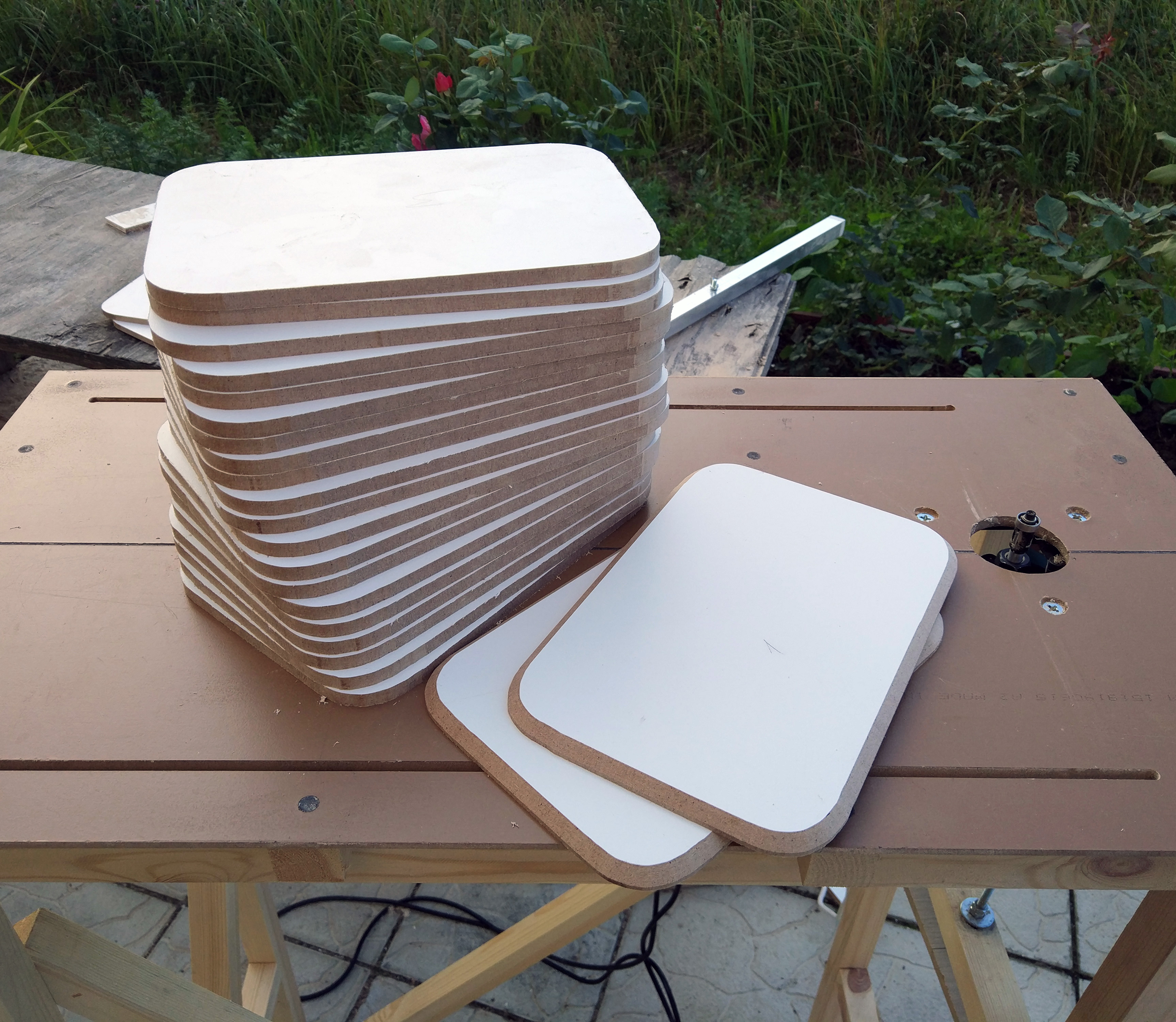
Все детали после фрезеровки. Будущие крышки лежат отдельно.
Тут должно быть фото выпила отверстий в слоях, но Джонни уже сделал монтаж.
Корпус колонки перед шлифовкой:
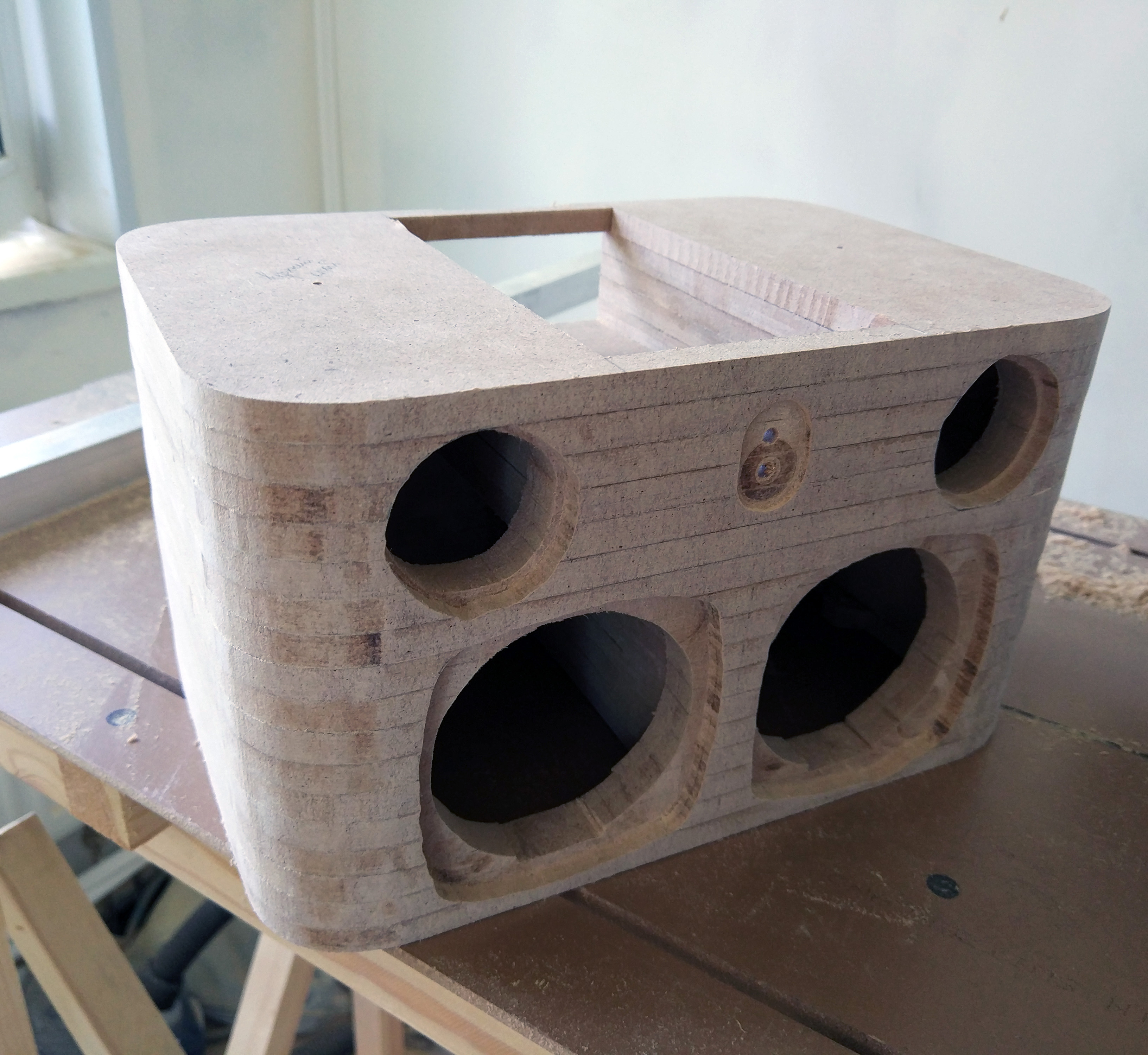
В конце корпус был покрашен в черный цвет, чтобы черные динамики не выделялись на нем темными пятнами после покрытия декоративным материалом.
Фрезерный стол в действии: фрезеровка углов по шаблону:
Все детали после фрезеровки. Будущие крышки лежат отдельно.
Тут должно быть фото выпила отверстий в слоях, но Джонни уже сделал монтаж.
Корпус колонки перед шлифовкой:
В конце корпус был покрашен в черный цвет, чтобы черные динамики не выделялись на нем темными пятнами после покрытия декоративным материалом.
And, actually, this is how it looks in the assembled state:
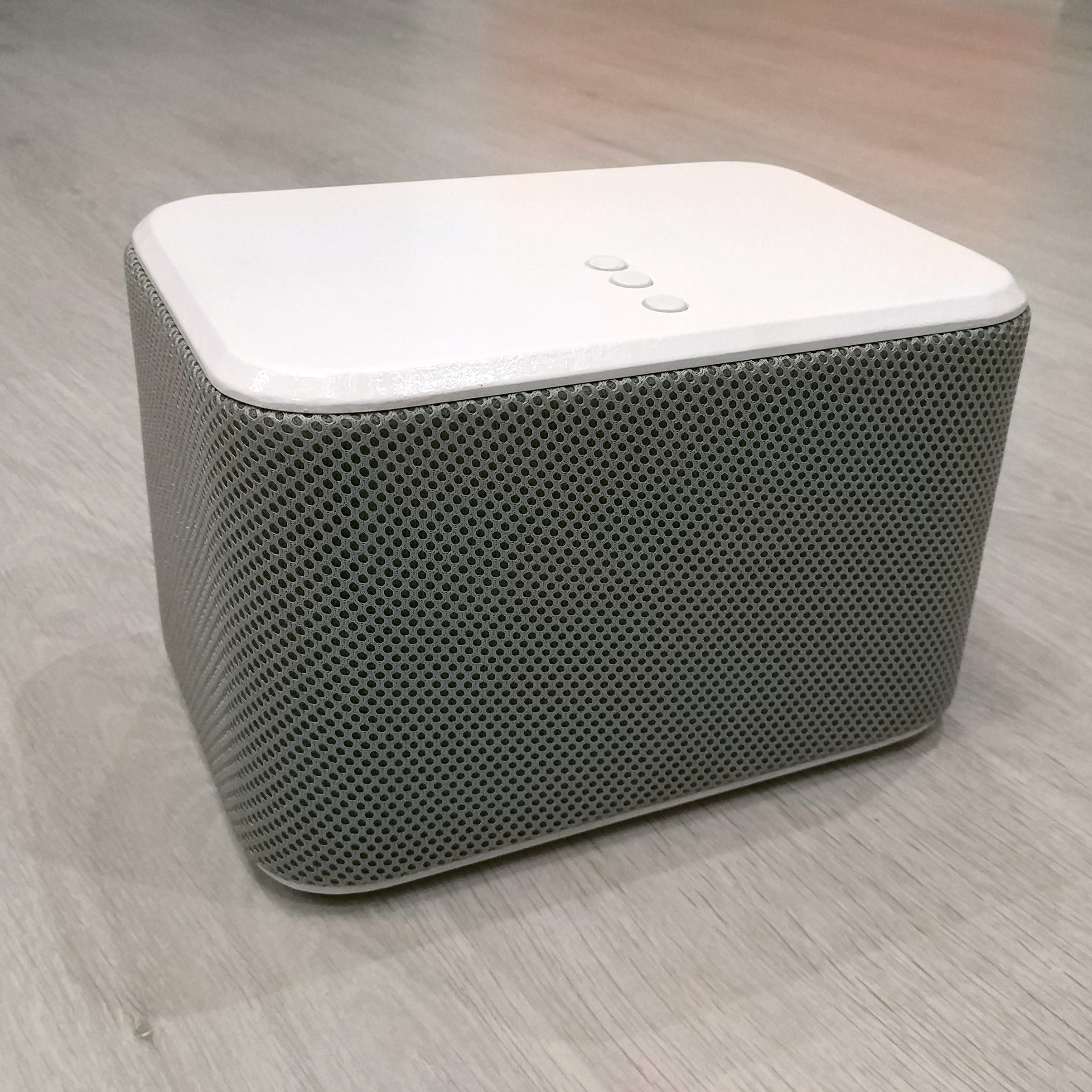
And from the back: Acoustic fabric is

glued on the outside , and white plugs covering its joint and electronics compartment are trimming the 40x25 cable channel. The top and bottom covers are painted with white enamel from a can of 5 layers (I regret very much that I didn’t choose acrylic paint - the enamel smelled badly, dried for a long time, and now actively collects dust and prints). Filling Speakers moved to the new building from the old. There are no complaints against them. These are all the same pair of midbass and a pair of tweeters connected to the amplifier through crossovers . Now for the amp. Since I refuse to use the analog "knob that" board Suptronics X400
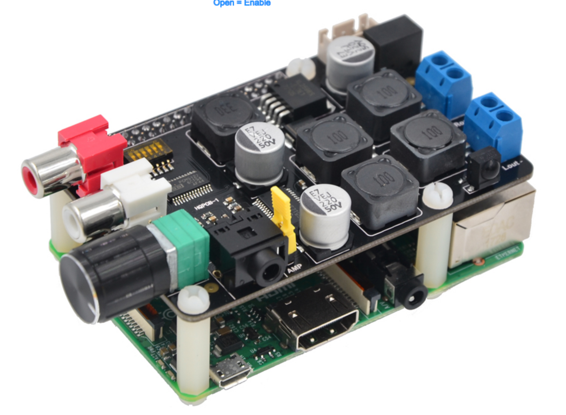
, then you can, as an option, just hide it in the bowels of the body. But the board is large, and because of its size, a couple of problems have appeared that have forced me to look for a replacement for it.
Thanks to IgorKKK , for making me understand Hifiberry products. Once upon a time I considered that their AMP + is only an audio amplifier, which should be hung over their DAC + DAC . But AMP + is an all-in-one board, and it could well have replaced the X400, only its performance is worse. But her descendant - AMP2 - with all the characteristics of OK. It is more compact than the X400, and its clamps are moved to a more convenient for mounting side.
For comparison, the sizes of X400 and AMP2 assembled with Raspberry Pi 3
Suptronics X400:
Hifiberry AMP2:
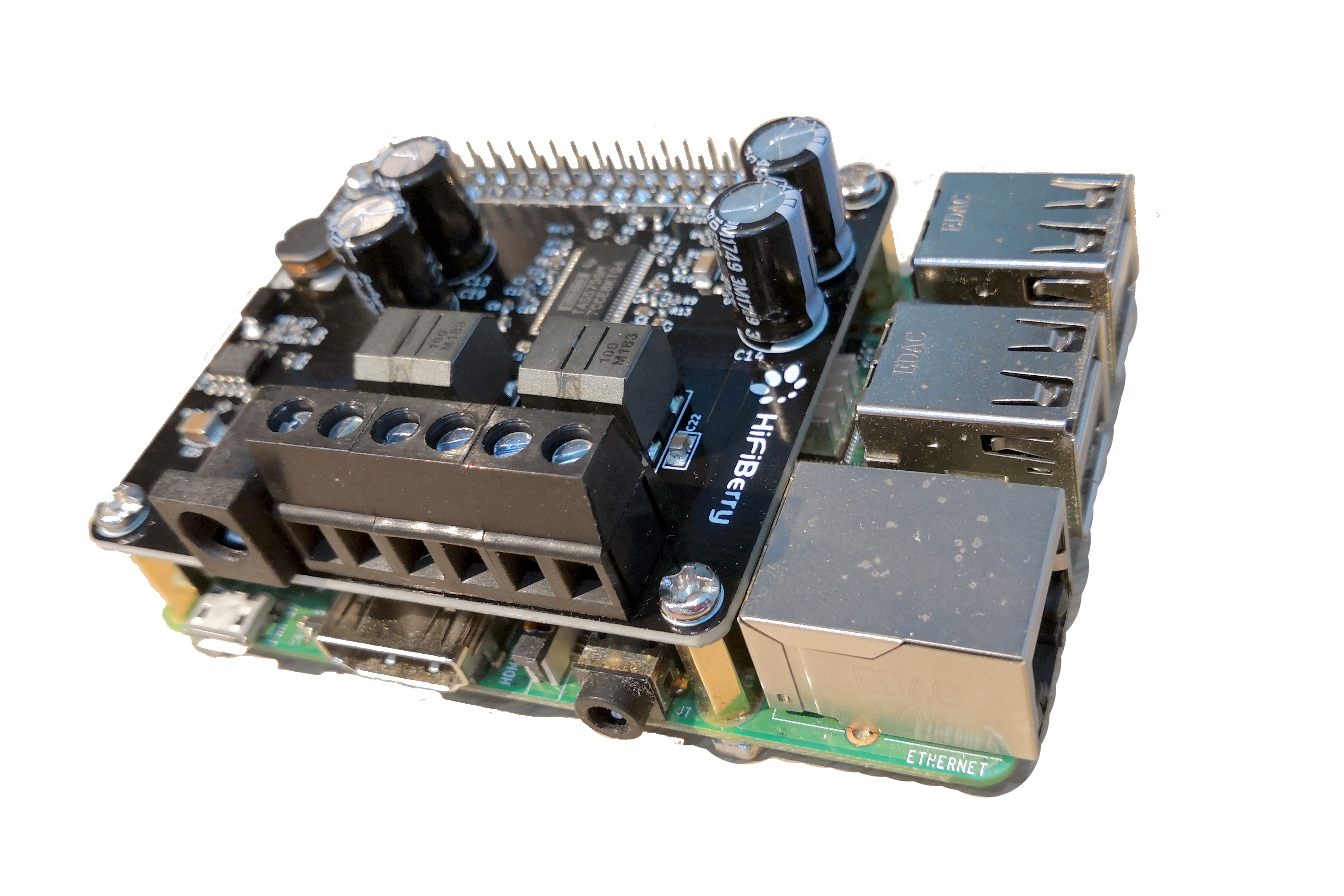
Hifiberry AMP2:
By the way, AMP2 on Aliexpress is not for sale, I ordered it directly from the manufacturer (I highly recommend - an order from Switzerland reached me in just 6 days). But AMP + is quite a buyable for AE.
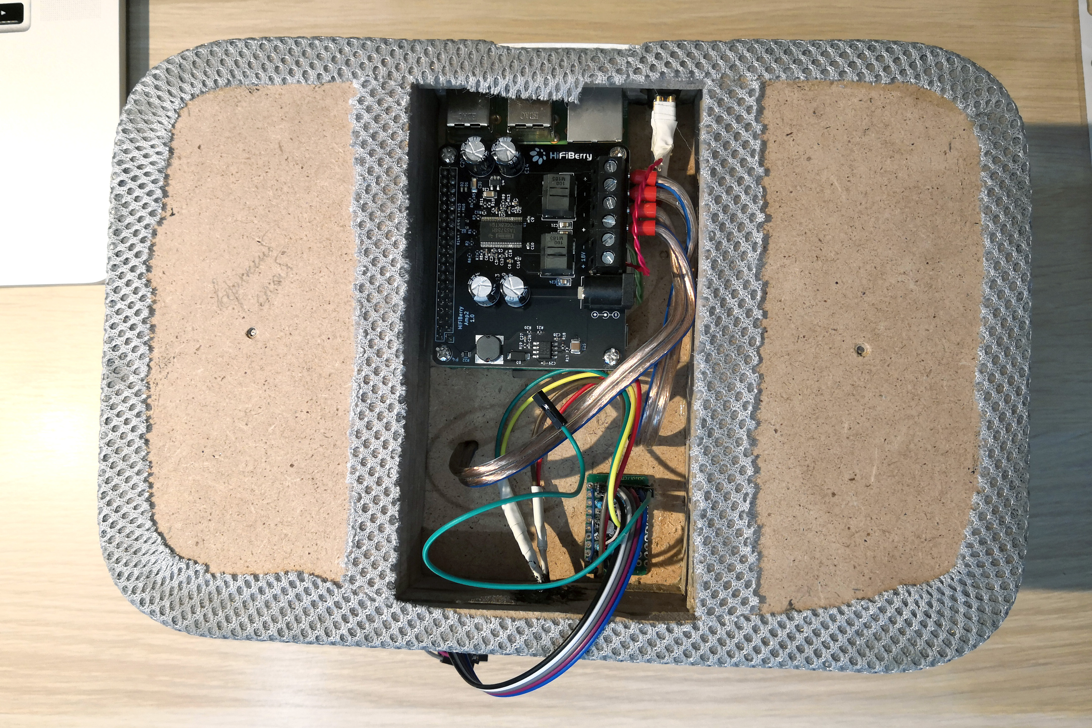
The location of the components inside the case
Сверху — «малинка», усилок и платы управления:
Снизу — динамики и кроссоверы:
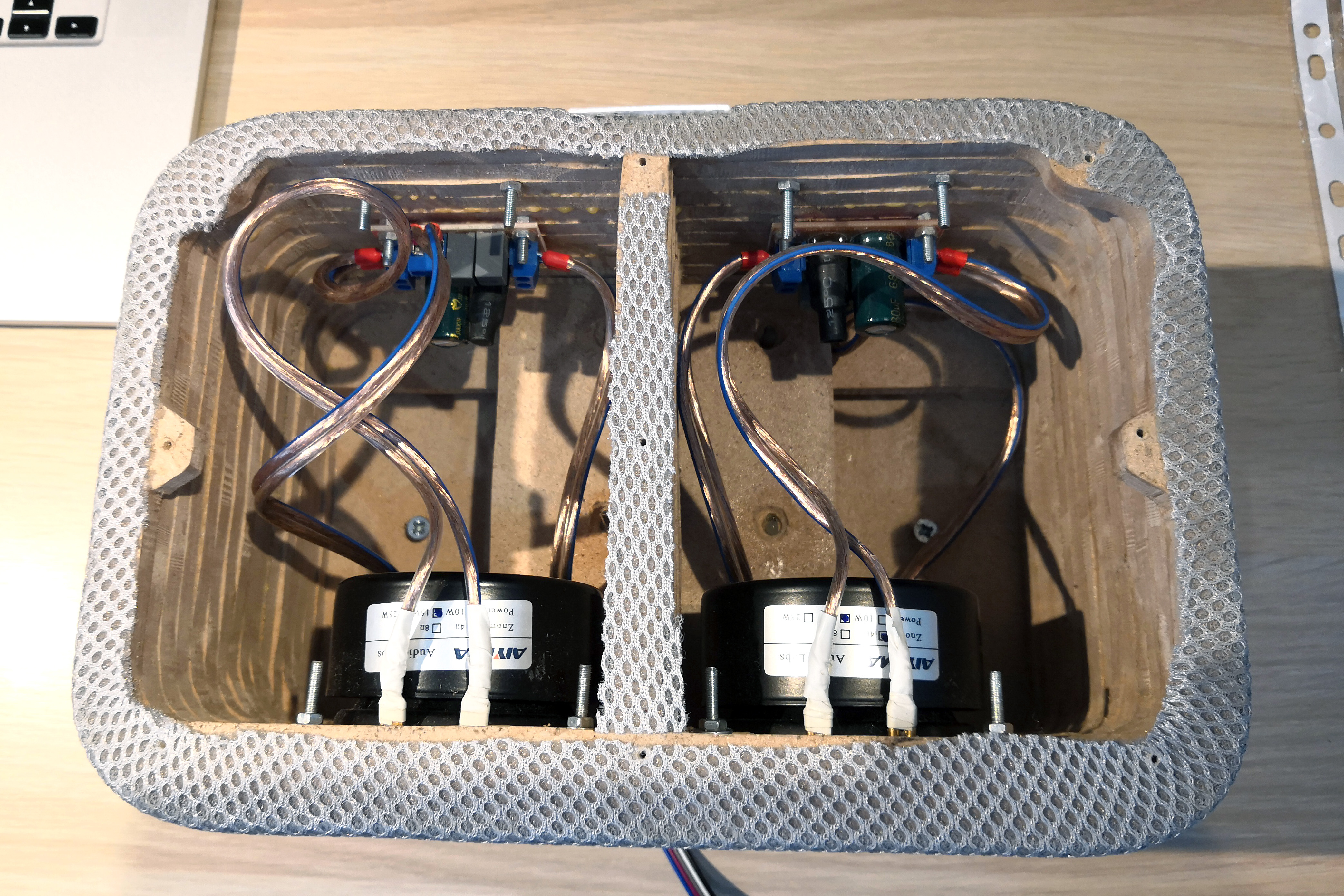
Снизу — динамики и кроссоверы:
Controls
In the previous version, the playback control was controlled by one small board with a button and an LED. Now the board had to be divided. The first board - with the “play / pause”, “volume -” and “volume +” buttons - is located under the top cover, the second one - which controls the flashing of the LEDs - in the compartment with the “raspberry”.
Circuit board for particularly inquisitive minds
Физические платы разделены на схеме серой линией.

Немного комментариев по схеме.
Справа все тривиально — три кнопки с тремя парами защитных резисторов, защищающих входные пины от выгорания.
Слева интереснее. Сразу бросается в глаза схема включения синего светодиода LED2. Принцип её работы прост, но неочевиден. Здесь используется тот факт, что все GPIO-пины общего пользования по умолчанию работают как входные (input). При включении питания с пина +3.3V подается напряжение, которое гонит ток через ограничительный резистор R1, синий светодиод LED2 и пин OUT1 (который пока еще не OUT, а IN, поэтому-то через него можно пропускать ток на вход). Когда Raspbian загружен полностью, запускается мой демон, который переводит пин OUT1 в режим output и подает на него напряжение +3.3V (HIGH). Разность потенциалов, падающая на участке «R1-LED2» становится равной 0V, и светодиод гаснет. Т.о. колонка сигнализирует о полной готовности к работе.
Белый светодиод работает в трех режимах:
горит постоянно — колонка воспроизводит музыку;
мигает редко и плавно — колонка в режиме паузы;
мигает часто и резко — нажата какая-либо кнопка.
Включением и отключением белого диода управляет пин OUT2, а плавностью мигания — пин OUT3. Когда нужна плавность мигания, через пин OUT3 на затвор MOSFET-а Q1 подается логическая 1 (HIGH, +3,3V), транзистор открывает участок цепи «R12-C1-Q1». И тогда при установке пина OUT2 в уровень HIGH (+3.3V), ток начинает заряжать конденсатор C1 и по мере его заряда зажигает светодиод LED1. А при установке пина OUT2 в уровень LOW (0V), конденсатор постепенно разряжается через светодиод, плавно уменьшая уровень его яркости до 0. Несложно посчитать, что время полного заряда/разряда конденсатора составляет примерно 3 секунды, оптимальный, на мой взгляд, период мигания.
Finally, software and UX
Web interface became more functional, more pleasant, and learned how to load the album cover for the current composition. All code is still available to anyone on Github .
Comparison with version 2.0
| Было | Стало |
|---|---|
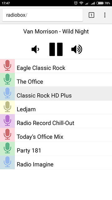 | 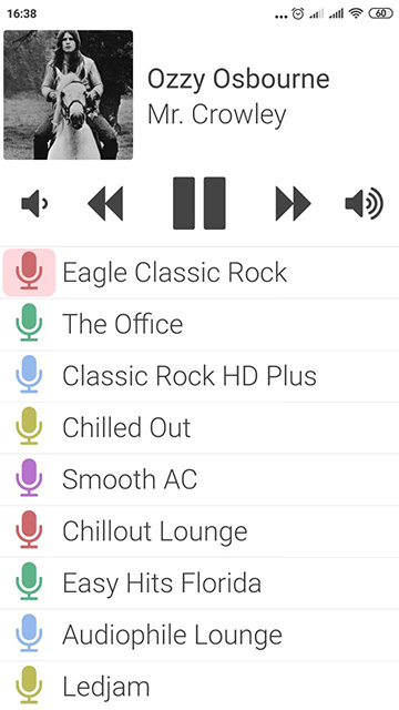 |
The long-click handling has been added to the logic of the physical buttons:
play / pause: short press - start / stop playback; long press - switch the station to the next one on the list;
volume: short press - change volume once; long press - continuous volume change.
Well, what's next?
The photo shows that the building was going in the summer, and he had enough time for running in and refinement. At the moment, both appearance and sound quality and usability suit both my home and (most importantly) me. And although so far I see no reason for reworking this body and / or replacing its parts, I don’t intend to stop there. The plans include turning this speaker into a voice assistant, as well as manufacturing a mini-column for a nursery based on the Raspberry Pi Zero in a case printed on a 3D printer. So wait for new articles in the near future!