Operating systems from scratch; Level 0
- Transfer
- Tutorial
 Good afternoon / evening / night / morning! There is one experimental course on operating systems. He is at Stanford University. But some of the materials are available to everyone. In addition to slides, full descriptions of practical exercises are available.
How is this course different from others? Most of the code is written independently and executed on a very real modern hardware. The Raspberry Pi 3 model B was chosen as the target platform . Those. fairly current architecture AArch64. ARMv8 Cortex-A53, four cores, 64-bit and that's it. Rust is selected as the main programming language . Which is safe, fast, without GC and so on. It, Rust, is supposed to be studied during the course.
There is about disks, file systems, input-output operations, threads / processes, scheduling, virtual memory, protection and security, interrupts, concurrency and synchronization. As in any other self-respecting course. The difference in the relevance of the material and in the amount of practice. Coddit will have a lot .
Translator's Note
If you wanted to see the literal translation, then it will not be. Instead, I will try to make the text useful and understandable. For example, in places that are relevant only to Stanford students, I will post information useful to others. There may be a little slang, a little unrelated to the original illustrations and a small number of additional comments. For the sake of readability, there will be no explicit Translator ™ Notes. The text can be considered an artistic translation or an article based on motives. I am not a welder - I will not be offended.
How did I find out about this course? Someone posted a link to Hacker News . I accidentally saw and imbued. I poked course materials myself and eventually decided to translate this matter.
Overview
In this part, we will set up the raspberry and the necessary tools. As a result, we will have a raspberry flashing LED. There are four main stages. To begin with, we need to make sure that the Pi's connection with the computer works for itself. Run the pre-prepared program. In the second stage, we will figure out how to connect LEDs. About the breadboard and wiring. In the third stage we collectprettycode and run it on the Pi. We will install a cross compiler aarch64-none-elfand try it in practice. And at the fourth stage, we rewrite this whole thing in Rust.
A couple of useful links:
- BCM2837 processor documentation - mainly about peripherals
- Colorful, comprehensive article about breadboard and wiring
- About using GPIO in the raspberry
- Briefly about the basic Rust syntax for those who already do pretty good programming
- An official textbook on Rust in angelic (the Russian version is not ready yet - you can help with the translation)
- Rusty Types for Solid Safety
- Lifetime Cheat Sheet in Rust
- Container cheat sheet in Rust (blue text clickable)
Phase 0: Getting Started
Before completing the course, you should get yourself into direct use of a unix-like operating system. It can be Linux, BSD or macOS defined git, wget, tar, screenand make. Theoretically, it can work in Windows 10 with the linux subsystem, but no one checked for sure. At least this configuration is not supported. Those. there are no ready-made recipes for winders and it is recommended to install Ubuntu LST or Fedora .

From iron we need:
- Raspberry Pi 3 model B (required with BCM2837)
- Breadboard, it’s also a prototyping board
- microSD card (plus adapter / adapter)
- USB-UART adapter (CP2102 USB TTL)
- Ten multi-color LEDs
- 100 ohm and 1 kOhm resistors, four each
- wiring
In the discussion on reddit, there are links to amazon with what might be required. However, all this can be bought at any other store. Including offline. In addition to all this, you can buy more of any components to your taste.
Attention : raspberry is sensitive to electrostatics. Try not to touch the contacts with your bare hands. You will not be killed by electric shock and will not even be scratched, but the raspberry itself can quite incapacitate itself. Ground yourself.
When all this is available, you can pull off the task code:
git clone https://web.stanford.edu/class/cs140e/assignments/0-blinky/skeleton.git 0-blinky
cd assignment0
make fetch
Feel free to explore the contents yourself.
Phase 1: Cooking raspberries

The first thing we need to do is configure the CP2102 adapter. It is needed for communication between the computer and the Pi. In addition to this, the raspberry receives through it the vital 5 volts. On one side of the USB, on the other five pieces, in the middle of the shawl.
Driver setup
On Linux, everything should work right out of the box. On poppies you will need to install a driver. Download this archive and unpack it. We launch SiLabsUSBDriverDisk.dmgand agree with the points on the sale of the soul under license. After that we start on the mounted volume Silicon Labs VPC Driver.pkg. Install and reboot.
Try plugging the CP2102 into a free USB slot. If everything works, then the appropriate files should appear in /dev. In the case of poppy /dev/tty.SLAB_USBtoUART. In the case of Linux, something like /dev/ttyUSB0. Write it down - come in handy. We take out the adapter.
Connect raspberries
Now connect the Raspberry Pi to the CP2102. Here is the connector matching table:
| CP2102 Connectors | Raspberry Pi Connectors |
|---|---|
| + 5v | four |
| GND | 6 |
| Rxd | eight |
| Txd | ten |
Numbering of pins on a raspberry (there is still an interactive version):
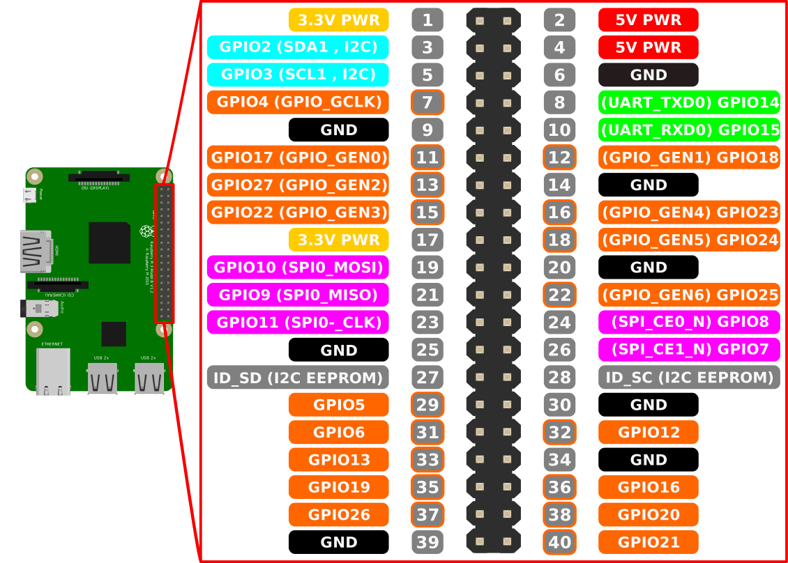
Everything together will look like this (wire colors can be chosen arbitrarily):


Important : check and recheck the connections before connecting this all to the computer. We need fresh raspberries, not burnt jam.
If you have confidence in the correct pairing of raspberries and adapter - you can still connect CP2102 to your computer.
Launch
Raspberry Pi loads programs from a microSD card during power-up. Right now we’ll figure out how to cook it.
First, we need to drop the files from the cloned repository onto the microSD-shku. Namely, those that are in the folder files/firmware. Those. bootcode.bin, config.txtand start.elf. Copy them to the root of the flash card. If suddenly these files are not in the cloned repository - you forgot about make fetch.
Why do we needbootcode.bin,config.txtandstart.elf?
This is all the raspberry bootloader.bootcode.bin- first bootloader. Its task is to downloadstart.elf. Which configures the processor according to the contents of the fileconfig.txt. After that, he downloadskernel8.imgand transfers control to him. By the way, where is he?
Now copy files/activity-led-blink.binfrom the repo to the root of the flash card and give this file a name kernel8.img. Unmount the card and pull it out. Make sure that raspberry is turned off. Then we insert the card into the raspberry and connect the raspberry to the food. We should see a blinking LED on the raspberry and on the CP2102 adapter. The flashing of the latter means that some data is being transferred there.
Data? What data? In order to see them, we need to connect a serial terminal emulator to CP2102 and read what happens there. We will use screen because it is installed on both Linux and macOS. Remember the path to the device from the folder /devand run
screen /dev/<имя> 115200On Linux, you may need to use sudoto run this command. However, you can add your user to the group dialoutand not write before this command sudoconstantly:
sudo gpasswd --add <имя-пользователя> dialoutOne way or another, but we should see greetings from raspberries. To exit screen, press <ctrl-a> kand then respond yto the exit offer.
Phase 2: Flashing LED
At this stage, we will connect the 16th pin of the GPIO (physical contact No. 36) of the raspberry to the LED on the breadboard. Let's check its work using a pre-prepared binary with firmware. Make sure that the raspberry is turned off.
GPIO: General Purpose I / O
As the name implies, GPIO is a common mechanism for transferring data / signals between any two devices through electrical contacts.
The raspberry-colored GPIO pins can work as inputs or as outputs . When a contact is an output , it can be turned on or off. Turning on a contact means that you can take 3.3 volts from it. By shutting down, it is meant that no current flows through this contact. When the GPIO pin is the input , Malinka checks to see if it has 3.3 volts or not.
These contacts are incredibly, breathtakingly universal and can be used to implement a huge range of different functions. Details can be found in the documentation . Documentation is not just attached. It can, and sometimes necessary, be read during the course.
LED connection.
Let's start by building such a diagram:
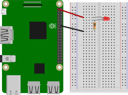
If you have never used a breadboard model, it is recommended to read (or at least see the pictures) in this guide . In our circuit, we connect the LED to the 3.3 volt contact (pin No. 1) and to the contact with zero potential (number 14). Pay attention to the correct connection of the LED. Over its short leg should be connected through a resistor to pin 14 (zero potential or earth (ground) on the other). After that, you can connect the raspberry to power. The LED will light up (if everything is connected correctly). If the LED is turned over, then it simply will not light up. He is, after all, the same diode as any of his friends.
If everything worked with a uniformly lit LED, then you can try to blink on it. We chop off raspberries from food. Now reconnect the LED from pin 1 to pin 36 (GPIO 16) like this:
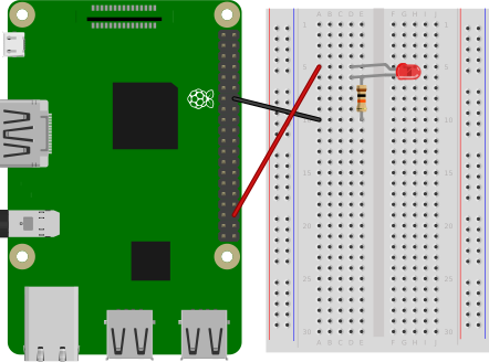
We take out the memory card again. We copy to it files/gpio16-blink.binunder the name kernel8.imginstead of the old with the same name. We put the card back and connect the raspberry to the power. Now the LED should blink uncontrollably.
Phase 3: Cute C
This time we will write a prog program that will do the same as gpio16-blink.bin. In order to be able to compile a nice little box for raspberries, we need a cross-compiler for aarch64-none-elf.
Cross compiler installation
We need to install the GNU toolchain for the architecture aarch64-none-elf(the gcc compiler and its company like objcopy).
Under macOS
First, install the homebrew package manager . If already installed, then this part can be skipped.
- Install Xcode tools for the command line. A dialog box will appear. When it appears - click "Install", "Continue" or whatever is usually there.
xcode-select--install - Run the Homebrew installation script. One will guide you through the rest of the installation process.
/usr/bin/ruby -e "$(curl -fsSL https://raw.githubusercontent.com/Homebrew/install/master/install)"
Now install the aarch64-none-elf toolchain using homebrew.
brew tap SergioBenitez/osxct
brew install aarch64-none-elf
Check if everything is installed correctly:
$ aarch64-none-elf-gcc --version
aarch64-none-elf-gcc (GCC) 7.2.0
Copyright (C) 2017 Free Software Foundation, Inc.
This is free software; see the source for copying conditions.  There isNO
warranty; not even for MERCHANTABILITY or FITNESS FOR A PARTICULAR PURPOSE.
Under linux
- Download and unzip aarch64-none-elf-linux-x64.tar.gz . After that, move
arch64-none-elfto/usr/local/bin:wget https://web.stanford.edu/class/cs140e/files/aarch64-none-elf-linux-x64.tar.gz tar -xzvf aarch64-none-elf-linux-x64.tar.gz sudo mv aarch64-none-elf /usr/local/bin - Add
/usr/local/bin/aarch64-none-elf/binto the environment variablePATH. How exactly - it depends on your particular Linux distribution. In most cases, the following should be added~/.profile:PATH="/usr/local/bin/aarch64-none-elf/bin:$PATH" - Check if everything is fine. As a result, we should get the gcc version and all that.
aarch64-none-elf-gcc --version
You can compile it yourself from the source if such a desire arises. More details here .
Now a little about iron
The interaction of the vast majority of modern hardware devices with software is carried out by mapping it into a Memory-mapped I / O memory . The bottom line is: you can communicate with devices as if it was just a certain part of the memory. At the same time, a specification is provided about what will happen when writing or reading certain addresses in memory. Addresses are usually divided into pieces of 32 or 64 bits, which are called registers. Registers can be read only, write, or both.
How do we know which registers and why to use, and where in memory they are? Manufacturers of various devices write documentation for these same devices. Usually they are called datasheets (data sheet), manuals (device manual), well, or just documentation. There is no general widespread format for documenting devices. Sometimes the documentation may be insufficient or it may not be at all. The ability to read and understand hardware documentation is quite a useful skill and in some ways even art.
In-memory GPIO
The documentation for many of the peripheral devices that the Rasbperry Pi has can be found in BCM2837 ARM Peripherals Manual . You can read about GPIO on page 89.
Padaji, in the same place in places about BCM2835, and we have BCM2837. Is this normal?
If you open the manual, then you can see in many places the mention of BCM2835. We just took a guide to it and fixed some errors. Well, the title was changed to BCM2837. BCM2837 and BCM2835 have the same peripheral devices with the same relative addresses in memory. The main difference in the overall configuration of physical memory. The base physical address of the peripheral devices on the BCM2837 is0x3F000000, unlike0x20000000in the BCM2835. However, both chips map these addresses to0x7E000000. Briefly on the BCM2837, the "peripheral" address0x7EXXXXXXwill be on the physical address0x3FXXXXXX. The above documentation has been modified to take this into account.
For our task, the following registers are enough for us:
| name | address | description | the size | read / write |
|---|---|---|---|---|
| GPFSEL1 | 0x7E200004 | GPIO Function Select 1 | 32 bits | both |
| GPSET0 | 0x7E20001C | GPIO Pin Output Set 0 | 32 bits | record only |
| Gpclr0 | 0x7E200028 | GPIO Pin Output Clear 0 | 32 bits | record only |
Taschetto it is directly copied directly from the documentation from page 90.
Now read the documentation for the register GPFSELnon pages 91 and 92. We write to this register to configure the pins as output or input. What should be the value in each register field GPFSEL1to configure output No. 16 of the GPIO so that it becomes an output?
Now again we read the documentation on page 95. About registers GPSET0and GPCLR0. We write in the register GPSET0to enable the contact. And in GPCLR0to turn off. What value do we need to write to these registers to turn on / off pin 16?
Code writing
In the phase3/turnip directory there is a draft code for building a binary file for raspberries. For now, we can do without explaining why we need it crt0.S, layout.ldand Makefile. Instead, focus on blinky.c. In it you will find that the addresses of all three registers we need are already indicated in the upper part. In addition, there are a couple of functions that can create a time delay. The task is to supplement the function mainso that pin No. 16 of the GPIO is configured as an output, and then it turns on and off for the LED to blink.
When the code is ready, it should be tested. To get started, compile it by running makein the directory phase3/. If everything is fine and there are no errors, a file will be created blinky.bin. We rename it to kernel8.img, copy to a microSD-card and run it all on the raspberry. If you already have one working kernel8.img, you can proceed to the next phase.
Tips:
Configuring / enabling / disabling pins can be implemented in one line of code.
Here will be useful operators are<<,|,&and~.
You can use the hexadecimal and binary forms in the string. For the number three, something like0x03and,0b011respectively.
Phase 4: Rust
This time we will write a program similar gpio16-blink.bin, but already in Rust. We write the code in phase4/src/lib.rs.
Install Rust and Xargo
In order to compile programs in Rust, we should install this same compiler. In addition, we will install xargowhich is a wrapper associated with the package manager cargo. Xargo allows us to compile our code for the Rasbperry Pi and all that.
- Let's go to https://rustup.rs/ and follow the instructions for installation
rustup. Make sure Rust was installed correctly by runningrustc --version. - Now we use
rustupandcargo(which was installed with rustc in the last step) to install the Rust night assembly. At the same time, we will install the sources of the standard library. And ofxargocourse.rustup default nightly-2018-01-09 rustup component add rust-src cargo install xargo - We check the installed commands and make sure that the versions of all this correspond to what we want from them:
$ rustc --version
rustc 1.25.0-nightly (b5392f545 2018-01-08)
$ xargo --version
xargo 0.3.10
cargo 0.25.0-nightly (a88fbace4 2017-12-29)
Now we have a completely working Rust compiler.
Code writing
To write code in a file, phase4/src/lib.rsyou need to know at least the following constructs:
1) You can read from and write to what's behind the bare pointers ( *mut T) using the read_volatile()and methods write_volatile(). For example, we have declared this:
const A: *mutu32 = 0x12as *mutu32;
const B: *mutu32 = 0x34as *mutu32;
We can write a 32-bit unsigned integer with an address 0x12in a cell with an address 0x34something like this:
B.write_volatile(A.read_volatile());2) Local variables are declared using the construct let имя_переменной = некое_выражение;.
You can read Afrom the previous example (i.e. the value located at the address 0x12) into a variable like this:
let value = A.read_volatile();3) Call the function fn f(param: usize);can be like this: f(123);.
4) The block loopcan be used to endlessly repeat something:
loop {
    do_this_again_and_again();
}
5) Rust has the following bitwise operators:
!- inversion<<- left shift>>- shift to the right|- bitwise OR&- bit I.
Now you are ready to blink the LED from the Rust code. We write the code in phase4/src/lib.rs. Translate the code into a similar rust code (in function kmain). It has already announced the necessary registers and the "sleep" function, which creates a delay for a while. Use it all.
When you are ready to check your program, compile it by running makein the directory phase4. If everything is fine, a file will be created build/blinky.bin, which we rename to kernel8.imgand put on the microSD-card, which we then insert into the raspberry. When the LED flashes again - we can assume that this part of the tutorial is completed.
UPD Next Series









