We write our own virtual machine
- Transfer
- Tutorial
In this tutorial, I’ll show you how to write your own virtual machine (VM) capable of running programs in assembler, such as 2048 (my friend) or Roguelike (mine). If you can program, but want to better understand what is happening inside the computer and how programming languages work, then this project is for you. Writing your own virtual machine may seem a bit scary, but I promise that the topic is surprisingly simple and instructive.
The final code is about 250 lines in C. It suffices to know only the basics of C or C ++, such as binary arithmetic. Any Unix system (including macOS) is suitable for building and running. Several Unix APIs are used to customize the input and display of the console, but they are not essential for the main code. (Implementation of Windows support is welcome).
A virtual machine is a program that acts like a computer. It simulates a processor with several other hardware components, allowing you to perform arithmetic, read from memory and write there, and interact with input-output devices, like a real physical computer. Most importantly, VM understands machine language that you can use to program.
How much hardware a particular VM mimics depends on its purpose. Some VMs reproduce the behavior of one particular computer. People no longer have NES, but we can still play games for NES, simulating hardware at the software level. These emulators must accurately recreate every detail.and each major hardware component of the original device.
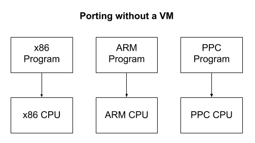
Other VMs do not correspond to any specific computer, but partially correspond to several at once! This is primarily done to facilitate software development. Imagine that you want to create a program that runs on multiple computer architectures. A virtual machine provides a standard platform that provides portability. No need to rewrite the program in different assembler dialects for each architecture. It is enough to make only a small VM in each language. After that, any program can be written only once in the virtual machine assembler language.

The Java Virtual Machine (JVM) is a very successful example. The JVM itself is relatively average in size; it is small enough for the programmer to understand. This allows you to write code for thousands of different devices, including phones. After implementing a JVM on a new device, any written Java, Kotlin or Clojure program can work on it unchanged. The only costs will be only the overhead of the VM itself and further abstraction from the machine level. This is usually a pretty good compromise.
VMs do not have to be large or omnipresent to provide similar benefits. Older video games often used small VMs to create simple scripting systems .
VMs are also useful for secure program isolation. One application is garbage collection. There is no trivial way to implement automatic garbage collection on top of C or C ++, since the program cannot see its own stack or variables. However, the VM is “out” of the running program and can observe all references to the memory cells in the stack. Ethereum smart contracts are
another example of this behavior . Smart contracts are small programs that are executed by each validation node in the blockchain. That is, the operators allow the execution on their machines of any programs written by complete strangers without any opportunity to study them in advance. To prevent malicious actions, they are performed onVMs that do not have access to the file system, network, disk, etc. Ethereum is also a good example of portability. Thanks to VM, you can write smart contracts without taking into account the features of multiple platforms.
Our VM will simulate a fictional computer called the LC-3 . It is popular for teaching students to assembler. Here is a simplified set of commands compared to x86 , but all the basic concepts that are used in modern CPUs are preserved.
First, you need to simulate the necessary hardware components. Try to understand what each component represents, but do not worry if you are not sure how it fits into the big picture. Let's start by creating a file on C. Each piece of code from this section should be placed in the global scope of this file.
The LC-3 computer has 65,536 memory cells (2 16 ), each of which contains a 16-bit value. This means that it can store only 128 KB - much less than you used to! In our program, this memory is stored in a simple array:
The register is a slot for storing one value in the CPU. Registers are similar to the "workbench" of the CPU. In order for it to work with some piece of data, it must be in one of the registers. But since there are only a few registers, at any one time only a minimum amount of data can be downloaded. Programs bypass this problem by loading values from memory into registers, calculating values into other registers, and then storing the final results back into memory.
There are only 10 registers in the LC-3 computer, each for 16 bits. Most of them are general assignments, but some are assigned roles.
General purpose registers can be used to perform any software calculations. The instruction counter is an unsigned integer that is the memory address of the next instruction to execute. The condition flags give us information about the previous calculation.
Like memory, we will store registers in an array:
An instruction is a command that tells the processor to perform some fundamental task, for example, add two numbers together. The instruction has an opcode ( opcode ) indicating the type of task being performed, as well as a set of parameters that provide input data for the task being performed.
Each opcode is one task that the processor “knows” how to perform. There are 16 opcodes in LC-3. A computer can only calculate the sequence of these simple instructions. The length of each instruction is 16 bits, and the left 4 bits store the operation code. The rest are used to store parameters.
We will discuss in detail later what each instruction does. At this point, determine the following opcodes. Make sure to keep this order in order to get the correct enum value:
The register
Each processor has multiple status flags to signal various situations. The LC-3 uses only three condition flags that indicate the sign of the previous calculation.
We have finished setting up the hardware components of our virtual machine! After adding the standard inclusions (see the link above), your file should look like this:
Now consider the LC-3 assembler program to get an idea of what the virtual machine actually performs. You do not need to know how to program in assembly language, or understand everything here. Just try to get a general idea of what's going on. Here is a simple "Hello World":
As in C, the program performs one operator from top to bottom. But unlike C, there are no nested regions
Please note that the names of some operators correspond to opcodes that we defined earlier. We know that in instructions for 16 bits, but each line looks as if with a different number of characters. How is such a discrepancy possible?
This happens because the code we read is written in assembly language — in readable and writable form with plain text. A tool called an assembler, converts each line of text into a 16-bit binary instruction, understandable to the virtual machine. This binary form, which is essentially an array of 16-bit instructions, is called machine code and is actually executed by the virtual machine.

Commands
Cycles and conditions are performed using goto-like instructions. Here is another example that counts up to 10.
Once again, the previous examples just give an idea what the VM is doing. To write a VM, you do not need a complete understanding of the assembler. As long as you follow the appropriate procedure for reading and executing instructions, any LC-3 program will work correctly, regardless of its complexity. In theory, a VM can even launch a browser or an operating system like Linux!
If you think deeply, this is a philosophically great idea. The programs themselves can perform arbitrarily complex actions that we never expected and may not be able to understand. But at the same time, all their functionality is limited to simple code that we write! We both know everything and nothing about how each program works. Turing mentioned this wonderful idea:
Here is the exact description of the procedure to write:
You can ask the question: “But if the cycle continues to increase the counter in the absence of,
Let's start studying this process on the example of the main cycle:
Now your task is to make the correct implementation for each opcode. Detailed specification of each instruction is contained in the project documentation . From the specification you need to know how each instruction works, and write an implementation. It is easier than it seems. Here I will demonstrate how to implement two of them. Code for the rest can be found in the next section.
The instruction
There are two lines in the diagram, because there are two different “modes” for this instruction. Before I explain the modes, let's try to find similarities between them. Both start with four identical bits
Thus, we know where to save the result, and we know the first number to add. It remains only to find out the second number for addition. Here the two lines start to differ. Notice that the top 5th bit is 0, and the bottom one is 1. This bit corresponds to either the direct mode or the register mode.. In the register mode, the second number is stored in the register, like the first. It is marked as
In direct mode, instead of adding the contents of the register, the immediate value is embedded in the instruction itself. This is convenient because the program does not need additional instructions for loading this number into a register from memory. Instead, it is already inside the manual when we need it. The tradeoff is that only small numbers can be stored there. To be precise, a maximum of 2 5 = 32. This is most useful for increasing counters or values. You can write in assembler like this:
Here is an excerpt from the specification:
This is similar to what we discussed. But what is “value expansion”? Although in immediate mode, the value of only 5 bits, it needs to be added with a 16-bit number. These 5 bits should be expanded to 16 to match another number. For positive numbers, we can fill in the missing bits with zeros and get the same value. However, for negative numbers this does not work. For example, −1 in five bits is
The specification has the last sentence:
Earlier, we defined the flags enum condition, and now it's time to use these flags. Every time a value is written to a register, we need to update the flags to indicate its sign. Write the function for reuse:
Now we are ready to write code for
This section has a lot of information, so let's summarize.
You may be stunned by the writing of 15 more instructions. However, the information obtained here can be reused. Most instructions use a combination of value expansion, various modes, and flag updates.
LDI means "indirect" or "indirect" load (load indirect). This instruction is used to load the register values from a place in memory. Specification on page 532.
Here is what the binary layout looks like:

In contrast
As before, you need to expand this 9-bit value, but this time add it to the current one
This may seem to be a devious way to read from memory, but it is necessary. The instruction is
As before, after writing the value in, you
Here is the code for this case: (
As I said, for this instruction we used a significant part of the code and knowledge obtained earlier when writing
Now you need to implement the remaining instructions. Follow the specifications and use the code already written. The code for all instructions is given at the end of the article. We will not need two of the opcodes listed above: this
In this section are complete implementations of the remaining instructions if you are stuck.
(not used)
The LC-3 provides several predefined routines for performing common tasks and interacting with I / O devices. For example, there are procedures for receiving input from the keyboard and outputting lines to the console. They called the system interrupt routines (trap routines), which you can think of as an operating system or an API for LC-3. Each subroutine is assigned an interrupt code (trap code), which identifies it (similarly to the opcode). For its execution, the instruction

Set the enum for each interrupt code:
You may be wondering why interrupt codes are not included in the instructions. This is because they do not actually add any new functionality to the LC-3, but only provide a convenient way to accomplish the task (like system functions in C). In the official LC-3 simulator, the interrupt codes are written in assembler . When you call the interrupt code, the computer moves to the address of this code. The CPU executes the procedure instructions, and when completed it is
There is no specification how to implement interrupt handling routines: just what they should do. In our VM, we will do a little differently, writing them in C. When calling the interrupt code, the C function will be called. After its operation, the instruction will continue.
Although procedures can be written in assembler and in a physical computer LC-3 and will be, this is not the best option for VM. Instead of writing your own primitive I / O procedures, you can use those that are available on our OS. This will improve the performance of the virtual machine on our computers, simplify the code and provide a higher level of abstraction for portability.
Add
As with the instructions, I will show you how to implement one procedure, and do the rest yourself.
The interrupt code is
To display a string, we must give the interrupt routine a string to display. This is done by storing the address of the first character in
From the specification:
Notice that, unlike C lines, the characters here are not stored in one byte, but in one location in memory . The LC-3's memory location is 16 bits, so each character in the string has a size of 16 bits. To display this in a C function, you need to convert each value to a character and output them separately.
Nothing more is required for this procedure. Interrupt routines are pretty simple if you know C. Now go back to the specification and implement the rest. As with the instructions, the full code can be found at the end of this manual.
This section contains complete implementations of the remaining interrupt routine.
We talked a lot about loading and executing instructions from memory, but how do instructions generally get into memory? When converting an assembler program into machine code, the result is a file containing an array of instructions and data. It can be downloaded by simply copying the contents directly to the address in memory.
The first 16 bits of the program file indicate the address in memory where the program should start. This address is called origin . It should be read first, after which the rest of the data is read from the file into memory.
Here is the code for loading the program into LC-3 memory:
Note that for each loaded value it is called
We also add a convenient function for
Some special registers are not available from the regular register table. Instead, a special address is reserved for them in memory. To read and write to these registers, you simply read and write to their memory. They are called memory-mapped registers . They are usually used to interact with special hardware devices.
For our LC-3, you need to implement two memory-mapped registers. This is the keyboard status register (
Although keyboard input can be queried with
Memory-mapped registers make access to memory a bit difficult. We cannot read and write to the memory array directly, but instead should call special functions — the setter and the getter. After reading the memory from the KBSR register, the getter checks the keyboard and updates both locations in memory.
This is the last component of the virtual machine! If you have implemented the remaining interrupt handling procedures and instructions, then you are almost ready to try it!
Everything written should be added to the C file in the following order:
This section contains some tedious details needed to access the keyboard and work correctly. There is nothing interesting or informative about the work of virtual machines. Feel free to copy-paste!
If you are trying to start a VM in an operating system other than Unix, such as Windows, these functions should be replaced with the corresponding Windows functions.
The code for extracting the path from the program arguments and displaying the use case if they are missing.
Unix-specific terminal input customization code.
When the program is interrupted, we want to return the normal console settings.
Now you can build and run a LC-3 virtual machine!
If the program does not work correctly, most likely you have incorrectly encoded some instruction. It can be difficult to debug. I recommend simultaneously reading the assembler code of the program - and using the debugger, step by step execute the virtual machine instructions one by one. When reading the code, make sure the VM goes to the proper instruction. If there is a discrepancy, then you will find out which instruction caused the problem. Re-read the specification and re-check the code.
Here is an advanced way of executing instructions, which significantly reduces the size of the code. This is a completely optional section.
Since C ++ supports powerful generics during the compilation process, we can create parts of instructions using the compiler. This method reduces duplication of code and is actually closer to the hardware level of the computer.
The idea is to reuse the steps that are common to each instruction. For example, some instructions use indirect addressing or expansion of the value and adding it to the current value
Considering the instruction as a sequence of steps, we see that each instruction is just a permutation of several smaller steps. We will use bit flags to mark which steps to perform for each instruction. The value
Note: I learned about this technique from an NES emulator developed by Bisqwit . If you are interested in emulation or NES, I highly recommend its videos.
The remaining versions of C ++ are using already written code. The full version is here .
The final code is about 250 lines in C. It suffices to know only the basics of C or C ++, such as binary arithmetic. Any Unix system (including macOS) is suitable for building and running. Several Unix APIs are used to customize the input and display of the console, but they are not essential for the main code. (Implementation of Windows support is welcome).
Note: this VM is a competent program . So you are already reading its source code right now! Each code snippet will be shown and explained in detail, so you can be sure: nothing is missing. The final code is created by interlacing blocks of code. Project repository here .
1. Table of Contents
- Table of contents
- Introduction
- LC-3 architecture
- Assembly language examples
- Run programs
- Implementation instructions
- Cheat sheet for instructions
- Interrupt Handling Procedures
- Interrupt Handler Cheat Sheet
- Download programs
- Memory mapped registers
- Platform Features
- Starting a virtual machine
- Alternative C ++ Method
2. Introduction
What is a virtual machine?
A virtual machine is a program that acts like a computer. It simulates a processor with several other hardware components, allowing you to perform arithmetic, read from memory and write there, and interact with input-output devices, like a real physical computer. Most importantly, VM understands machine language that you can use to program.
How much hardware a particular VM mimics depends on its purpose. Some VMs reproduce the behavior of one particular computer. People no longer have NES, but we can still play games for NES, simulating hardware at the software level. These emulators must accurately recreate every detail.and each major hardware component of the original device.
Other VMs do not correspond to any specific computer, but partially correspond to several at once! This is primarily done to facilitate software development. Imagine that you want to create a program that runs on multiple computer architectures. A virtual machine provides a standard platform that provides portability. No need to rewrite the program in different assembler dialects for each architecture. It is enough to make only a small VM in each language. After that, any program can be written only once in the virtual machine assembler language.
Note: the compiler solves similar problems by compiling a standard high-level language for different processor architectures. VM creates one standard CPU architecture that is simulated on various hardware devices. One of the advantages of the compiler is that there is no overhead during runtime, like a VM. Although compilers work well, writing a new compiler for multiple platforms is very difficult, so VMs are still useful. In reality, at different levels and VM, and compilers are used together.
The Java Virtual Machine (JVM) is a very successful example. The JVM itself is relatively average in size; it is small enough for the programmer to understand. This allows you to write code for thousands of different devices, including phones. After implementing a JVM on a new device, any written Java, Kotlin or Clojure program can work on it unchanged. The only costs will be only the overhead of the VM itself and further abstraction from the machine level. This is usually a pretty good compromise.
VMs do not have to be large or omnipresent to provide similar benefits. Older video games often used small VMs to create simple scripting systems .
VMs are also useful for secure program isolation. One application is garbage collection. There is no trivial way to implement automatic garbage collection on top of C or C ++, since the program cannot see its own stack or variables. However, the VM is “out” of the running program and can observe all references to the memory cells in the stack. Ethereum smart contracts are
another example of this behavior . Smart contracts are small programs that are executed by each validation node in the blockchain. That is, the operators allow the execution on their machines of any programs written by complete strangers without any opportunity to study them in advance. To prevent malicious actions, they are performed onVMs that do not have access to the file system, network, disk, etc. Ethereum is also a good example of portability. Thanks to VM, you can write smart contracts without taking into account the features of multiple platforms.
3. LC-3 architecture
Our VM will simulate a fictional computer called the LC-3 . It is popular for teaching students to assembler. Here is a simplified set of commands compared to x86 , but all the basic concepts that are used in modern CPUs are preserved.
First, you need to simulate the necessary hardware components. Try to understand what each component represents, but do not worry if you are not sure how it fits into the big picture. Let's start by creating a file on C. Each piece of code from this section should be placed in the global scope of this file.
Memory
The LC-3 computer has 65,536 memory cells (2 16 ), each of which contains a 16-bit value. This means that it can store only 128 KB - much less than you used to! In our program, this memory is stored in a simple array:
/* 65536 locations */uint16_t memory[UINT16_MAX];Registers
The register is a slot for storing one value in the CPU. Registers are similar to the "workbench" of the CPU. In order for it to work with some piece of data, it must be in one of the registers. But since there are only a few registers, at any one time only a minimum amount of data can be downloaded. Programs bypass this problem by loading values from memory into registers, calculating values into other registers, and then storing the final results back into memory.
There are only 10 registers in the LC-3 computer, each for 16 bits. Most of them are general assignments, but some are assigned roles.
- 8 general purpose registers (
R0-R7) - 1 command counter register (
PC) - 1 register of conditions flags (
COND)
General purpose registers can be used to perform any software calculations. The instruction counter is an unsigned integer that is the memory address of the next instruction to execute. The condition flags give us information about the previous calculation.
enum
{
    R_R0 = 0,
    R_R1,
    R_R2,
    R_R3,
    R_R4,
    R_R5,
    R_R6,
    R_R7,
    R_PC, /* program counter */
    R_COND,
    R_COUNT
};
Like memory, we will store registers in an array:
uint16_t reg[R_COUNT];Instruction set
An instruction is a command that tells the processor to perform some fundamental task, for example, add two numbers together. The instruction has an opcode ( opcode ) indicating the type of task being performed, as well as a set of parameters that provide input data for the task being performed.
Each opcode is one task that the processor “knows” how to perform. There are 16 opcodes in LC-3. A computer can only calculate the sequence of these simple instructions. The length of each instruction is 16 bits, and the left 4 bits store the operation code. The rest are used to store parameters.
We will discuss in detail later what each instruction does. At this point, determine the following opcodes. Make sure to keep this order in order to get the correct enum value:
enum
{
    OP_BR = 0, /* branch */
    OP_ADD,    /* add  */
    OP_LD,     /* load */
    OP_ST,     /* store */
    OP_JSR,    /* jump register */
    OP_AND,    /* bitwise and */
    OP_LDR,    /* load register */
    OP_STR,    /* store register */
    OP_RTI,    /* unused */
    OP_NOT,    /* bitwise not */
    OP_LDI,    /* load indirect */
    OP_STI,    /* store indirect */
    OP_JMP,    /* jump */
    OP_RES,    /* reserved (unused) */
    OP_LEA,    /* load effective address */
    OP_TRAP    /* execute trap */
};
Note: Intel x86 architecture has hundreds of instructions, while other architectures, such as ARM and LC-3, have very few instructions. Small sets of instructions are called RISC , and larger ones are called CISC . Large sets of instructions, as a rule, do not provide fundamentally new features, but often simplify the writing of assembly code . A single CISC instruction can replace multiple RISC instructions. However, CISC processors are more complex and expensive to design and manufacture. This and other compromises do not allow to call the "optimal" design .
Condition flags
The register
R_CONDstores condition flags that provide information about the last calculation performed. This allows programs to check logical conditions, such as if (x > 0) { ... }. Each processor has multiple status flags to signal various situations. The LC-3 uses only three condition flags that indicate the sign of the previous calculation.
enum
{
    FL_POS = 1 << 0, /* P */
    FL_ZRO = 1 << 1, /* Z */
    FL_NEG = 1 << 2, /* N */
};
Note: (The symbol<<is called the left shift operator .(n << k)Shifts the bits to thenleft inkplaces. Thus, it1 << 2is equal4. Read here if you are not familiar with the concept. This will be very important).
We have finished setting up the hardware components of our virtual machine! After adding the standard inclusions (see the link above), your file should look like this:
{Includes, 12}
{Registers, 3}
{Opcodes, 3}
{Condition Flags, 3}4. Examples in assembly language
Now consider the LC-3 assembler program to get an idea of what the virtual machine actually performs. You do not need to know how to program in assembly language, or understand everything here. Just try to get a general idea of what's going on. Here is a simple "Hello World":
.ORIG x3000                        ; this is the address in memory where the program will be loaded
LEA R0, HELLO_STR                  ; load the address of the HELLO_STR string into R0
PUTs                               ; output the string pointed to by R0 to the console
HALT                               ; halt the program
HELLO_STR .STRINGZ "Hello World!"  ; store this string here in the program
.END                               ; mark the end of the file
As in C, the program performs one operator from top to bottom. But unlike C, there are no nested regions
{}or control structures, such as ifor while; just a simple list of operators. Therefore, it is much easier to perform. Please note that the names of some operators correspond to opcodes that we defined earlier. We know that in instructions for 16 bits, but each line looks as if with a different number of characters. How is such a discrepancy possible?
This happens because the code we read is written in assembly language — in readable and writable form with plain text. A tool called an assembler, converts each line of text into a 16-bit binary instruction, understandable to the virtual machine. This binary form, which is essentially an array of 16-bit instructions, is called machine code and is actually executed by the virtual machine.
Note: Although the compiler and assembler play a similar role in development, they are not the same. The assembler simply encodes what the programmer wrote in the text, replacing the characters with their binary representation and packing them into instructions.
Commands
.ORIGand .STRINGZlook like instructions, but no. These are assembler directives that generate a piece of code or data. For example, .STRINGZinserts a string of characters in the specified location of the binary program. Cycles and conditions are performed using goto-like instructions. Here is another example that counts up to 10.
AND R0, R0, 0                      ; clear R0
LOOP                               ; label at the top of our loop
ADD R0, R0, 1                      ; add 1 to R0 and store back in R0
ADD R1, R0, -10                    ; subtract 10 from R0 and store back in R1
BRn LOOP                           ; go back to LOOP if the result was negative
... ; R0 is now 10!
Note: for this manual, it is not necessary to learn assembly language. But if you're interested, you can write and build your own LC-3 programs with the help of LC-3 Tools .
5. Program execution
Once again, the previous examples just give an idea what the VM is doing. To write a VM, you do not need a complete understanding of the assembler. As long as you follow the appropriate procedure for reading and executing instructions, any LC-3 program will work correctly, regardless of its complexity. In theory, a VM can even launch a browser or an operating system like Linux!
If you think deeply, this is a philosophically great idea. The programs themselves can perform arbitrarily complex actions that we never expected and may not be able to understand. But at the same time, all their functionality is limited to simple code that we write! We both know everything and nothing about how each program works. Turing mentioned this wonderful idea:
“The opinion that machines cannot surprise a person with something, I believe, is based on one error, to which mathematicians and philosophers are particularly subject. I mean the assumption that if some fact has become the property of the mind, immediately all the consequences of this fact become the property of the mind. ” - Alan M. Turing
Procedure
Here is the exact description of the procedure to write:
- Load one instruction from memory at the address of the register
PC. - Increase case
PC. - See opcode to determine which type of instruction to execute.
- Execute the instruction using its parameters.
- Return to step 1.
You can ask the question: “But if the cycle continues to increase the counter in the absence of,
ifor whilewill the instructions not end?” The answer is no. As we already mentioned, some goto-like instructions change the flow of execution by jumping around PC. Let's start studying this process on the example of the main cycle:
intmain(int argc, constchar* argv[]){
    {Load Arguments, 12}
    {Setup, 12}
    /* set the PC to starting position *//* 0x3000 is the default */enum { PC_START = 0x3000 };
    reg[R_PC] = PC_START;
    int running = 1;
    while (running)
    {
        /* FETCH */uint16_t instr = mem_read(reg[R_PC]++);
        uint16_t op = instr >> 12;
        switch (op)
        {
            case OP_ADD:
                {ADD, 6}
                break;
            case OP_AND:
                {AND, 7}
                break;
            case OP_NOT:
                {NOT, 7}
                break;
            case OP_BR:
                {BR, 7}
                break;
            case OP_JMP:
                {JMP, 7}
                break;
            case OP_JSR:
                {JSR, 7}
                break;
            case OP_LD:
                {LD, 7}
                break;
            case OP_LDI:
                {LDI, 6}
                break;
            case OP_LDR:
                {LDR, 7}
                break;
            case OP_LEA:
                {LEA, 7}
                break;
            case OP_ST:
                {ST, 7}
                break;
            case OP_STI:
                {STI, 7}
                break;
            case OP_STR:
                {STR, 7}
                break;
            case OP_TRAP:
                {TRAP, 8}
                break;
            case OP_RES:
            case OP_RTI:
            default:
                {BAD OPCODE, 7}
                break;
        }
    }
    {Shutdown, 12}
}
6. Implementation instructions
Now your task is to make the correct implementation for each opcode. Detailed specification of each instruction is contained in the project documentation . From the specification you need to know how each instruction works, and write an implementation. It is easier than it seems. Here I will demonstrate how to implement two of them. Code for the rest can be found in the next section.
ADD
The instruction
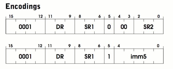
ADDtakes two numbers, adds them and stores the result in the register. Specification in the documentation on page 526. Each instruction is ADDas follows:There are two lines in the diagram, because there are two different “modes” for this instruction. Before I explain the modes, let's try to find similarities between them. Both start with four identical bits
0001. This is the opcode value for OP_ADD. The following three bits are marked DRfor output register. The output register is the storage location of the amount. The following three bits: SR1. This is the register containing the first number to add. Thus, we know where to save the result, and we know the first number to add. It remains only to find out the second number for addition. Here the two lines start to differ. Notice that the top 5th bit is 0, and the bottom one is 1. This bit corresponds to either the direct mode or the register mode.. In the register mode, the second number is stored in the register, like the first. It is marked as
SR2contained in bits two through zero. Bits 3 and 4 are not used. In assembly language it will be written like this:ADD R2 R0 R1 ; add the contents of R0 to R1 and store in R2.In direct mode, instead of adding the contents of the register, the immediate value is embedded in the instruction itself. This is convenient because the program does not need additional instructions for loading this number into a register from memory. Instead, it is already inside the manual when we need it. The tradeoff is that only small numbers can be stored there. To be precise, a maximum of 2 5 = 32. This is most useful for increasing counters or values. You can write in assembler like this:
ADD R0 R0 1 ; add 1 to R0 and store back in R0Here is an excerpt from the specification:
If bit [5] is 0, then the second source operand is derived from SR2. If bit [5] is 1, then the second source operand is obtained by extending the value of imm5 to 16 bits. In both cases, the second source operand is added to the contents of SR1, and the result is stored in DR. (p. 526)
This is similar to what we discussed. But what is “value expansion”? Although in immediate mode, the value of only 5 bits, it needs to be added with a 16-bit number. These 5 bits should be expanded to 16 to match another number. For positive numbers, we can fill in the missing bits with zeros and get the same value. However, for negative numbers this does not work. For example, −1 in five bits is
1 1111. If you just fill in with zeros, you get 0000 0000 0001 111132! Expanding the value prevents this problem by filling the bits with zeros for positive numbers and ones for negative numbers.uint16_t sign_extend(uint16_t x, int bit_count)
{
if ((x >> (bit_count - 1)) & 1) {
x |= (0xFFFF << bit_count);
}
return x;
}Note: if you are interested in binary negative numbers, you can read about the additional code . But this is not essential. Simply copy the code above and use it when the specification says to expand the value.
The specification has the last sentence:
Condition codes are set depending on whether the result is negative, zero or positive. (p. 526)
Earlier, we defined the flags enum condition, and now it's time to use these flags. Every time a value is written to a register, we need to update the flags to indicate its sign. Write the function for reuse:
voidupdate_flags(uint16_t r){
    if (reg[r] == 0)
    {
        reg[R_COND] = FL_ZRO;
    }
    elseif (reg[r] >> 15) /* a 1 in the left-most bit indicates negative */
    {
        reg[R_COND] = FL_NEG;
    }
    else
    {
        reg[R_COND] = FL_POS;
    }
}
Now we are ready to write code for
ADD:{
/* destination register (DR) */uint16_t r0 = (instr >> 9) & 0x7;
/* first operand (SR1) */uint16_t r1 = (instr >> 6) & 0x7;
/* whether we are in immediate mode */uint16_t imm_flag = (instr >> 5) & 0x1;
if (imm_flag)
{
uint16_t imm5 = sign_extend(instr & 0x1F, 5);
reg[r0] = reg[r1] + imm5;
}
else
{
uint16_t r2 = instr & 0x7;
reg[r0] = reg[r1] + reg[r2];
}
update_flags(r0);
}This section has a lot of information, so let's summarize.
ADDtakes two values and stores them in a register.- In register mode, the second value added is in the register.
- In direct mode, the second value is embedded in the right 5 bits of the instruction.
- Values shorter than 16 bits should be expanded.
- Each time an instruction changes case, the condition flags should be updated.
You may be stunned by the writing of 15 more instructions. However, the information obtained here can be reused. Most instructions use a combination of value expansion, various modes, and flag updates.
Ldi
LDI means "indirect" or "indirect" load (load indirect). This instruction is used to load the register values from a place in memory. Specification on page 532.
Here is what the binary layout looks like:
In contrast
ADD, there are no modes and fewer parameters. This time the opcode 1010, which corresponds to the enum value OP_LDI. Again, we see a three-bit DR(output register) for storing the loaded value. The remaining bits are marked as PCoffset9. This is an immediate value embedded in the instruction (similarly imm5). Since the instruction is loaded from memory, we can guess that this number is a kind of address that tells where to load the value. The specification explains in more detail:The address is calculated by extending the value bits[8:0]to 16 bits and adding this value to the incremented onePC. What is stored in memory at this address is the address of the data that will be loaded intoDR. (p. 532)
As before, you need to expand this 9-bit value, but this time add it to the current one
PC. (If you look at the run cycle, it PCincreased immediately after downloading this instruction). The resulting sum is the address of the memory location, and this address contains another value, which is the address of the value being loaded. This may seem to be a devious way to read from memory, but it is necessary. The instruction is
LDlimited to an address offset of 9 bits, while the memory requires 16 bits for the address.LDIuseful for loading values that are stored somewhere outside the current computer, but to use them, the destination address must be stored nearby. You can think of it as a local variable in C, which is a pointer to some data:// the value of far_data is an address// of course far_data itself (the location in memory containing the address) has an addresschar* far_data = "apple";
// In memory it may be layed out like this:// Address Label Value// 0x123: far_data = 0x456// ...// 0x456: string = 'a'// if PC was at 0x100// LDI R0 0x023// would load 'a' into R0As before, after writing the value in, you
DRshould update the flags:Condition codes are set depending on whether the result is negative, zero or positive. (p. 532)
Here is the code for this case: (
mem_readdiscuss in the next section):{
/* destination register (DR) */uint16_t r0 = (instr >> 9) & 0x7;
/* PCoffset 9*/uint16_t pc_offset = sign_extend(instr & 0x1ff, 9);
/* add pc_offset to the current PC, look at that memory location to get the final address */
reg[r0] = mem_read(mem_read(reg[R_PC] + pc_offset));
update_flags(r0);
}As I said, for this instruction we used a significant part of the code and knowledge obtained earlier when writing
ADD. Same with the rest of the instructions. Now you need to implement the remaining instructions. Follow the specifications and use the code already written. The code for all instructions is given at the end of the article. We will not need two of the opcodes listed above: this
OP_RTIand OP_RES. You can ignore them or give an error if they are called. When done, the main part of your VM can be considered complete!7. Cheat sheet for instructions
In this section are complete implementations of the remaining instructions if you are stuck.
RTI & RES
(not used)
abort();Bit "and"
{
    uint16_t r0 = (instr >> 9) & 0x7;
    uint16_t r1 = (instr >> 6) & 0x7;
    uint16_t imm_flag = (instr >> 5) & 0x1;
    if (imm_flag)
    {
        uint16_t imm5 = sign_extend(instr & 0x1F, 5);
        reg[r0] = reg[r1] & imm5;
    }
    else
    {
        uint16_t r2 = instr & 0x7;
        reg[r0] = reg[r1] & reg[r2];
    }
    update_flags(r0);
}
Bit "NOT"
{
    uint16_t r0 = (instr >> 9) & 0x7;
    uint16_t r1 = (instr >> 6) & 0x7;
    reg[r0] = ~reg[r1];
    update_flags(r0);
}
Branch
{
    uint16_t pc_offset = sign_extend((instr) & 0x1ff, 9);
    uint16_t cond_flag = (instr >> 9) & 0x7;
    if (cond_flag & reg[R_COND])
    {
        reg[R_PC] += pc_offset;
    }
}
Jump
RETlisted as a separate instruction in the specification, as this is a different command in the assembler. In fact, this is a special case JMP. REToccurs whenever R17 is equal.{
/* Also handles RET */uint16_t r1 = (instr >> 6) & 0x7;
reg[R_PC] = reg[r1];
}Jump register
{
    uint16_t r1 = (instr >> 6) & 0x7;
    uint16_t long_pc_offset = sign_extend(instr & 0x7ff, 11);
    uint16_t long_flag = (instr >> 11) & 1;
    reg[R_R7] = reg[R_PC];
    if (long_flag)
    {
        reg[R_PC] += long_pc_offset;  /* JSR */
    }
    else
    {
        reg[R_PC] = reg[r1]; /* JSRR */
    }
    break;
}
Load
{
    uint16_t r0 = (instr >> 9) & 0x7;
    uint16_t pc_offset = sign_extend(instr & 0x1ff, 9);
    reg[r0] = mem_read(reg[R_PC] + pc_offset);
    update_flags(r0);
}
Load register
{
    uint16_t r0 = (instr >> 9) & 0x7;
    uint16_t r1 = (instr >> 6) & 0x7;
    uint16_t offset = sign_extend(instr & 0x3F, 6);
    reg[r0] = mem_read(reg[r1] + offset);
    update_flags(r0);
}
Effective address load
{
    uint16_t r0 = (instr >> 9) & 0x7;
    uint16_t pc_offset = sign_extend(instr & 0x1ff, 9);
    reg[r0] = reg[R_PC] + pc_offset;
    update_flags(r0);
}
Store
{
    uint16_t r0 = (instr >> 9) & 0x7;
    uint16_t pc_offset = sign_extend(instr & 0x1ff, 9);
    mem_write(reg[R_PC] + pc_offset, reg[r0]);
}
Store indirect
{
    uint16_t r0 = (instr >> 9) & 0x7;
    uint16_t pc_offset = sign_extend(instr & 0x1ff, 9);
    mem_write(mem_read(reg[R_PC] + pc_offset), reg[r0]);
}
Store Register
{
    uint16_t r0 = (instr >> 9) & 0x7;
    uint16_t r1 = (instr >> 6) & 0x7;
    uint16_t offset = sign_extend(instr & 0x3F, 6);
    mem_write(reg[r1] + offset, reg[r0]);
}
8. Interrupt Handling Procedures
The LC-3 provides several predefined routines for performing common tasks and interacting with I / O devices. For example, there are procedures for receiving input from the keyboard and outputting lines to the console. They called the system interrupt routines (trap routines), which you can think of as an operating system or an API for LC-3. Each subroutine is assigned an interrupt code (trap code), which identifies it (similarly to the opcode). For its execution, the instruction
TRAPwith the code of the desired subroutine is called.Set the enum for each interrupt code:
enum
{
    TRAP_GETC = 0x20,  /* get character from keyboard */
    TRAP_OUT = 0x21,   /* output a character */
    TRAP_PUTS = 0x22,  /* output a word string */
    TRAP_IN = 0x23,    /* input a string */
    TRAP_PUTSP = 0x24, /* output a byte string */
    TRAP_HALT = 0x25/* halt the program */
};
You may be wondering why interrupt codes are not included in the instructions. This is because they do not actually add any new functionality to the LC-3, but only provide a convenient way to accomplish the task (like system functions in C). In the official LC-3 simulator, the interrupt codes are written in assembler . When you call the interrupt code, the computer moves to the address of this code. The CPU executes the procedure instructions, and when completed it is
PCreset to the location from which the interrupt was triggered.Note: this is why programs start with an address0x3000instead0x0. The lower addresses are left blank to leave room for the interrupt handling routine code.
There is no specification how to implement interrupt handling routines: just what they should do. In our VM, we will do a little differently, writing them in C. When calling the interrupt code, the C function will be called. After its operation, the instruction will continue.
Although procedures can be written in assembler and in a physical computer LC-3 and will be, this is not the best option for VM. Instead of writing your own primitive I / O procedures, you can use those that are available on our OS. This will improve the performance of the virtual machine on our computers, simplify the code and provide a higher level of abstraction for portability.
Note: One specific example is keyboard input. In the assembler version, a loop is used to continuously check the keyboard input. But after all so much CPU time is wasted! When using the proper OS function, the program can sleep to the input signal.
Add
TRAPone more switch to the multiple choice operator for the opcode :switch (instr & 0xFF)
{
case TRAP_GETC:
{TRAP GETC, 9}
break;
case TRAP_OUT:
{TRAP OUT, 9}
break;
case TRAP_PUTS:
{TRAP PUTS, 8}
break;
case TRAP_IN:
{TRAP IN, 9}
break;
case TRAP_PUTSP:
{TRAP PUTSP, 9}
break;
case TRAP_HALT:
{TRAP HALT, 9}
break;
}As with the instructions, I will show you how to implement one procedure, and do the rest yourself.
PUTS
The interrupt code is
PUTSused to output a string with a terminating zero (similar to printfin C). Specification on page 543. To display a string, we must give the interrupt routine a string to display. This is done by storing the address of the first character in
R0before starting processing. From the specification:
Display an ASCII character string on the console display. The characters are contained in consecutive memory locations, one character per cell, starting at the address specified inR0. The output is complete when a value is encountered in memoryx0000. (p. 543)
Notice that, unlike C lines, the characters here are not stored in one byte, but in one location in memory . The LC-3's memory location is 16 bits, so each character in the string has a size of 16 bits. To display this in a C function, you need to convert each value to a character and output them separately.
{
    /* one char per word */uint16_t* c = memory + reg[R_R0];
    while (*c)
    {
        putc((char)*c, stdout);
        ++c;
    }
    fflush(stdout);
}
Nothing more is required for this procedure. Interrupt routines are pretty simple if you know C. Now go back to the specification and implement the rest. As with the instructions, the full code can be found at the end of this manual.
9. Cheat Sheet on Interrupt Handling Procedures
This section contains complete implementations of the remaining interrupt routine.
Character input
/* read a single ASCII char */
reg[R_R0] = (uint16_t)getchar();
Character output
putc((char)reg[R_R0], stdout);
fflush(stdout);
Character input request
printf("Enter a character: ");
reg[R_R0] = (uint16_t)getchar();
Line output
{
    /* one char per byte (two bytes per word)
       here we need to swap back to
       big endian format */uint16_t* c = memory + reg[R_R0];
    while (*c)
    {
        char char1 = (*c) & 0xFF;
        putc(char1, stdout);
        char char2 = (*c) >> 8;
        if (char2) putc(char2, stdout);
        ++c;
    }
    fflush(stdout);
}
Program termination
puts("HALT");
fflush(stdout);
running = 0;
10. Download programs
We talked a lot about loading and executing instructions from memory, but how do instructions generally get into memory? When converting an assembler program into machine code, the result is a file containing an array of instructions and data. It can be downloaded by simply copying the contents directly to the address in memory.
The first 16 bits of the program file indicate the address in memory where the program should start. This address is called origin . It should be read first, after which the rest of the data is read from the file into memory.
Here is the code for loading the program into LC-3 memory:
voidread_image_file(FILE* file){
    /* the origin tells us where in memory to place the image */uint16_t origin;
    fread(&origin, sizeof(origin), 1, file);
    origin = swap16(origin);
    /* we know the maximum file size so we only need one fread */uint16_t max_read = UINT16_MAX - origin;
    uint16_t* p = memory + origin;
    size_t read = fread(p, sizeof(uint16_t), max_read, file);
    /* swap to little endian */while (read-- > 0)
    {
        *p = swap16(*p);
        ++p;
    }
}
Note that for each loaded value it is called
swap16. The LC-3 programs are written in direct byte order, but most modern computers use the reverse order. As a result, we need to flip every loaded one uint16. (If you accidentally use a strange computer like PPC , then you don’t need to change anything).uint16_t swap16(uint16_t x)
{
return (x << 8) | (x >> 8);
}Note: Byte order refers to how integer bytes are interpreted. In reverse order, the first byte is the least significant digit, and in the direct order - the opposite. As far as I know, the decision is mostly arbitrary. Different companies made different decisions, so now we have different implementations. For this project, you don’t need to know anything else about the byte order.
We also add a convenient function for
read_image_file, which takes the path for the string:intread_image(constchar* image_path){
FILE* file = fopen(image_path, "rb");
if (!file) { return0; };
read_image_file(file);
fclose(file);
return1;
}11. Memory mapped registers
Some special registers are not available from the regular register table. Instead, a special address is reserved for them in memory. To read and write to these registers, you simply read and write to their memory. They are called memory-mapped registers . They are usually used to interact with special hardware devices.
For our LC-3, you need to implement two memory-mapped registers. This is the keyboard status register (
KBSR) and the keyboard data register ( KBDR). The first indicates whether the key was pressed, and the second determines which key is pressed. Although keyboard input can be queried with
GETC, it blocks execution until input is received. KBSRand KBDRallow you to poll the state device, while continuing to execute the program, so that it remains responsive while waiting for input.enum
{
MR_KBSR = 0xFE00, /* keyboard status */
MR_KBDR = 0xFE02/* keyboard data */
};Memory-mapped registers make access to memory a bit difficult. We cannot read and write to the memory array directly, but instead should call special functions — the setter and the getter. After reading the memory from the KBSR register, the getter checks the keyboard and updates both locations in memory.
voidmem_write(uint16_t address, uint16_t val){
    memory[address] = val;
}
uint16_t mem_read(uint16_t address)
{
    if (address == MR_KBSR)
    {
        if (check_key())
        {
            memory[MR_KBSR] = (1 << 15);
            memory[MR_KBDR] = getchar();
        }
        else
        {
            memory[MR_KBSR] = 0;
        }
    }
    return memory[address];
}
This is the last component of the virtual machine! If you have implemented the remaining interrupt handling procedures and instructions, then you are almost ready to try it!
Everything written should be added to the C file in the following order:
{Memory Mapped Registers, 11}
{TRAP Codes, 8}
{Memory Storage, 3}
{Register Storage, 3}
{Functions, 12}
{Main Loop, 5}
12. Platform Features
This section contains some tedious details needed to access the keyboard and work correctly. There is nothing interesting or informative about the work of virtual machines. Feel free to copy-paste!
If you are trying to start a VM in an operating system other than Unix, such as Windows, these functions should be replaced with the corresponding Windows functions.
uint16_t check_key()
{
    fd_set readfds;
    FD_ZERO(&readfds);
    FD_SET(STDIN_FILENO, &readfds);
    structtimevaltimeout;
    timeout.tv_sec = 0;
    timeout.tv_usec = 0;
    return select(1, &readfds, NULL, NULL, &timeout) != 0;
}
The code for extracting the path from the program arguments and displaying the use case if they are missing.
if (argc < 2)
{
    /* show usage string */printf("lc3 [image-file1] ...\n");
    exit(2);
}
for (int j = 1; j < argc; ++j)
{
    if (!read_image(argv[j]))
    {
        printf("failed to load image: %s\n", argv[j]);
        exit(1);
    }
}
Unix-specific terminal input customization code.
structtermiosoriginal_tio;voiddisable_input_buffering(){
    tcgetattr(STDIN_FILENO, &original_tio);
    structtermiosnew_tio = original_tio;
    new_tio.c_lflag &= ~ICANON & ~ECHO;
    tcsetattr(STDIN_FILENO, TCSANOW, &new_tio);
}
voidrestore_input_buffering(){
    tcsetattr(STDIN_FILENO, TCSANOW, &original_tio);
}
When the program is interrupted, we want to return the normal console settings.
voidhandle_interrupt(int signal){
    restore_input_buffering();
    printf("\n");
    exit(-2);
}
signal(SIGINT, handle_interrupt);
disable_input_buffering();restore_input_buffering();{Sign Extend, 6}
{Swap, 10}
{Update Flags, 6}
{Read Image File, 10}
{Read Image, 10}
{Check Key, 12}
{Memory Access, 11}
{Input Buffering, 12}
{Handle Interrupt, 12}#include<stdio.h>#include<stdlib.h>#include<stdint.h>#include<string.h>#include<signal.h>#include<unistd.h>#include<fcntl.h>#include<sys/time.h>#include<sys/types.h>#include<sys/termios.h>#include<sys/mman.h>Starting a virtual machine
Now you can build and run a LC-3 virtual machine!
- Compile the program with your favorite compiler.
- Download the compiled version of 2048 or Rogue .
- Run the program with the obj file as an argument:
lc3-vm path/to/2048.obj - Play 2048!
Control the game using WASD keys.
Are you on an ANSI terminal(y/n)? y
+--------------------------+
|                          |
|                          |
|                          |
|                     2    |
|                          |
|   2                      |
|                          |
|                          |
|                          |
+--------------------------+
Debugging
If the program does not work correctly, most likely you have incorrectly encoded some instruction. It can be difficult to debug. I recommend simultaneously reading the assembler code of the program - and using the debugger, step by step execute the virtual machine instructions one by one. When reading the code, make sure the VM goes to the proper instruction. If there is a discrepancy, then you will find out which instruction caused the problem. Re-read the specification and re-check the code.
14. Alternative C ++ Method
Here is an advanced way of executing instructions, which significantly reduces the size of the code. This is a completely optional section.
Since C ++ supports powerful generics during the compilation process, we can create parts of instructions using the compiler. This method reduces duplication of code and is actually closer to the hardware level of the computer.
The idea is to reuse the steps that are common to each instruction. For example, some instructions use indirect addressing or expansion of the value and adding it to the current value
PC. Agree, it would be nice to write this code once for all instructions?Considering the instruction as a sequence of steps, we see that each instruction is just a permutation of several smaller steps. We will use bit flags to mark which steps to perform for each instruction. The value
1in the instruction number bit indicates that the compiler must include this section of the code for this instruction.template <unsigned op>
voidins(uint16_t instr){
uint16_t r0, r1, r2, imm5, imm_flag;
uint16_t pc_plus_off, base_plus_off;
uint16_t opbit = (1 << op);
if (0x4EEE & opbit) { r0 = (instr >> 9) & 0x7; }
if (0x12E3 & opbit) { r1 = (instr >> 6) & 0x7; }
if (0x0022 & opbit)
{
r2 = instr & 0x7;
imm_flag = (instr >> 5) & 0x1;
imm5 = sign_extend((instr) & 0x1F, 5);
}
if (0x00C0 & opbit)
{ // Base + offset
base_plus_off = reg[r1] + sign_extend(instr & 0x3f, 6);
}
if (0x4C0D & opbit)
{
// Indirect address
pc_plus_off = reg[R_PC] + sign_extend(instr & 0x1ff, 9);
}
if (0x0001 & opbit)
{
// BRuint16_t cond = (instr >> 9) & 0x7;
if (cond & reg[R_COND]) { reg[R_PC] = pc_plus_off; }
}
if (0x0002 & opbit) // ADD
{
if (imm_flag)
{
reg[r0] = reg[r1] + imm5;
}
else
{
reg[r0] = reg[r1] + reg[r2];
}
}
if (0x0020 & opbit) // AND
{
if (imm_flag)
{
reg[r0] = reg[r1] & imm5;
}
else
{
reg[r0] = reg[r1] & reg[r2];
}
}
if (0x0200 & opbit) { reg[r0] = ~reg[r1]; } // NOTif (0x1000 & opbit) { reg[R_PC] = reg[r1]; } // JMPif (0x0010 & opbit) // JSR
{
uint16_t long_flag = (instr >> 11) & 1;
pc_plus_off = reg[R_PC] + sign_extend(instr & 0x7ff, 11);
reg[R_R7] = reg[R_PC];
if (long_flag)
{
reg[R_PC] = pc_plus_off;
}
else
{
reg[R_PC] = reg[r1];
}
}
if (0x0004 & opbit) { reg[r0] = mem_read(pc_plus_off); } // LDif (0x0400 & opbit) { reg[r0] = mem_read(mem_read(pc_plus_off)); } // LDIif (0x0040 & opbit) { reg[r0] = mem_read(base_plus_off); } // LDRif (0x4000 & opbit) { reg[r0] = pc_plus_off; } // LEAif (0x0008 & opbit) { mem_write(pc_plus_off, reg[r0]); } // STif (0x0800 & opbit) { mem_write(mem_read(pc_plus_off), reg[r0]); } // STIif (0x0080 & opbit) { mem_write(base_plus_off, reg[r0]); } // STRif (0x8000 & opbit) // TRAP
{
{TRAP, 8}
}
//if (0x0100 & opbit) { } // RTIif (0x4666 & opbit) { update_flags(r0); }
}staticvoid(*op_table[16])(uint16_t)= {
ins<0>, ins<1>, ins<2>, ins<3>,
ins<4>, ins<5>, ins<6>, ins<7>,
NULL, ins<9>, ins<10>, ins<11>,
ins<12>, NULL, ins<14>, ins<15>
};Note: I learned about this technique from an NES emulator developed by Bisqwit . If you are interested in emulation or NES, I highly recommend its videos.
The remaining versions of C ++ are using already written code. The full version is here .
{Includes, 12}
{Registers, 3}
{Condition Flags, 3}
{Opcodes, 3}
{Memory Mapped Registers, 11}
{TRAP Codes, 8}
{Memory Storage, 3}
{Register Storage, 3}
{Functions, 12}
int running = 1;
{Instruction C++, 14}
{Op Table, 14}
intmain(int argc, constchar* argv[]){
    {Load Arguments, 12}
    {Setup, 12}
    enum { PC_START = 0x3000 };
    reg[R_PC] = PC_START;
    while (running)
    {
        uint16_t instr = mem_read(reg[R_PC]++);
        uint16_t op = instr >> 12;
        op_table[op](instr);
    }
    {Shutdown, 12}
}