Simple Scada in Python and Arduino
In continuation of the article about the possibility of building your own scada system in Python, I want to offer a practical application.
There was a need to control the air temperature in the server room of the enterprise.
Such a problem exists in small enterprises due to the limited number of personnel and technical equipment.
The problem is certainly not of a global scale, but, as a rule, at such enterprises server equipment is located in small rooms, sometimes in former copters or utility rooms.
Of course, air conditioning is installed there to effectively cool the equipment.
But this same air conditioner tends to break, as repairmen explain, either the "capacitor burned out" or the "freon is over."
After such emergency situations, IT engineers have a lot of problems; those who come across this will understand. The task is not difficult, in addition to the network there are many examples of implementation. For this purpose, it was decided to use the Arduino UNO and the temperature sensor DS18b20.
After reading the article , uploaded to Arduino
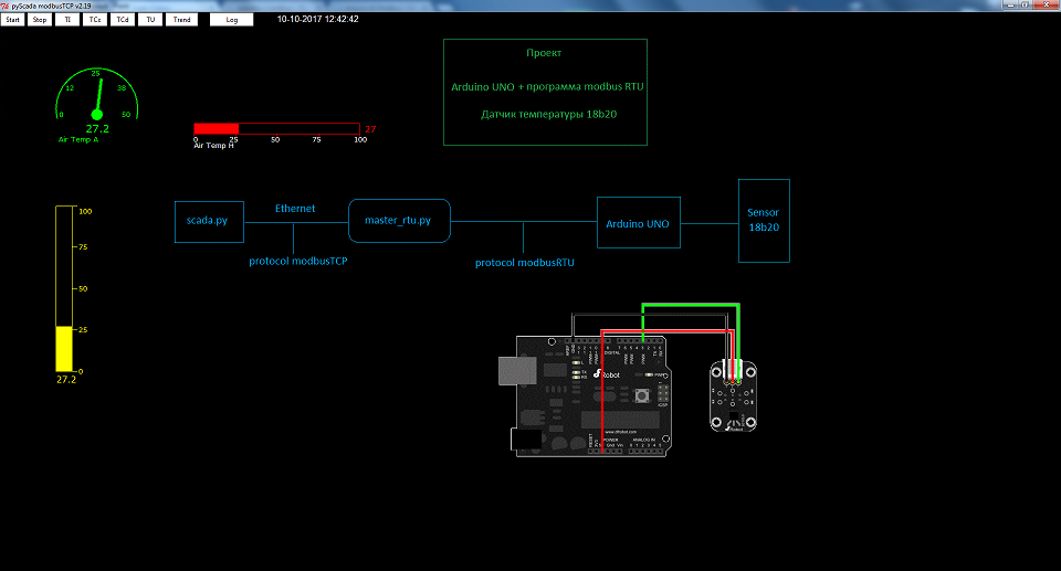
Now Arduino acts as a Slave device with address 10 and operates on the modbus RTU protocol. In addition, the program continuously polls the DS18b20 temperature sensor and records the current readings at address 2 of the READ_INPUT_REGISTERS register.
Since the Slave device is connected to the computer via a USB interface with a dedicated com port, you can use the program to receive data from it:
On the one hand, this program is a Master for polling slaves using the modbus RTU protocol, and on the other hand, it is a Slave device and transmits data to the upper level using the modbus TCP protocol.
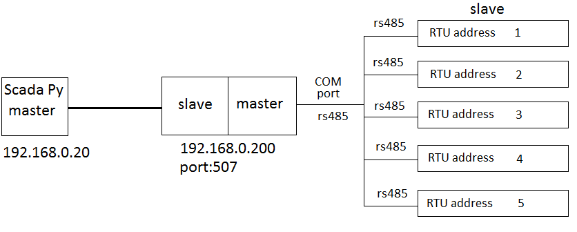
The master_rtu.py program is used if you have to collect readings from several devices using the modbus RTU protocol and / or rs485 interface. The com file address and rtu address of the slave devices are indicated in the configuration file. In addition, the polling registers and the addresses of the registers into which the received data are recorded are indicated.
Description of setting.cfg settings file for master_rtu.py :
In this configuration, the modbus RTU Slave device with address 10 will be polled. In the READ_INPUT_REGISTERS register at address 2, the measured temperature value will be read and written into the READ_INPUT_REGISTERS register at address 0 slave of the program part for modbus TCP polling.

In the ai.cfg analog signal settings file, write:
Those. we will take the measured value of the temperature of the register READ_INPUT_REGISTERS at 0x00, place it on the canvas at coordinates x = 100, y = 100 and display the mnemonic diagram using the arrow object.
In the settings.cfg settings file for scada.py we write:
The measurement results can be displayed on various objects of the mnemonic diagram, including monitoring on a dynamic chart.

Source code can be downloaded here.
There was a need to control the air temperature in the server room of the enterprise.
Such a problem exists in small enterprises due to the limited number of personnel and technical equipment.
The problem is certainly not of a global scale, but, as a rule, at such enterprises server equipment is located in small rooms, sometimes in former copters or utility rooms.
Of course, air conditioning is installed there to effectively cool the equipment.
But this same air conditioner tends to break, as repairmen explain, either the "capacitor burned out" or the "freon is over."
After such emergency situations, IT engineers have a lot of problems; those who come across this will understand. The task is not difficult, in addition to the network there are many examples of implementation. For this purpose, it was decided to use the Arduino UNO and the temperature sensor DS18b20.
After reading the article , uploaded to Arduino
the program.
#include "ModbusRtu.h"
#include
#define ID   10     // адрес ведомого
Modbus slave(ID, 0, 0);
// массив данных modbus
uint16_t au16data[20];
const int analogInPin = A0;
int8_t state = 0;
int DS18S20_Pin = 2; //DS18S20 Signal pin on digital 2
OneWire ds(DS18S20_Pin);  // on digital pin 2
int tmp =0;
void setup() {
  // настраиваем последовательный порт ведомого
  slave.begin( 9600 );
  // зажигаем светодиод на 100 мс
}
void loop() {
   float temperature = getTemp();
  tmp= temperature * 10;
  au16data[2] = tmp;
  state = slave.poll( au16data, 11);
  delay(10);
}
float getTemp(){
  //returns the temperature from one DS18S20 in DEG Celsius
  byte data[12];
  byte addr[8];
  if ( !ds.search(addr)) {
      //no more sensors on chain, reset search
      ds.reset_search();
      return -1000;
  }
  if ( OneWire::crc8( addr, 7) != addr[7]) {
      Serial.println("CRC is not valid!");
      return -1000;
  }
  if ( addr[0] != 0x10 && addr[0] != 0x28) {
      Serial.print("Device is not recognized");
      return -1000;
  }
  ds.reset();
  ds.select(addr);
  ds.write(0x44,1); // start conversion, with parasite power on at the end
  byte present = ds.reset();
  ds.select(addr);
  ds.write(0xBE); // Read Scratchpad
  for (int i = 0; i < 9; i++) { // we need 9 bytes
    data[i] = ds.read();
  }
  ds.reset_search();
  byte MSB = data[1];
  byte LSB = data[0];
  float tempRead = ((MSB << 8) | LSB); //using two's compliment
  float TemperatureSum = tempRead / 16;
  return TemperatureSum;
}
Now Arduino acts as a Slave device with address 10 and operates on the modbus RTU protocol. In addition, the program continuously polls the DS18b20 temperature sensor and records the current readings at address 2 of the READ_INPUT_REGISTERS register.
Since the Slave device is connected to the computer via a USB interface with a dedicated com port, you can use the program to receive data from it:
modbus_rtu.py.
#!/usr/bin/env python
import sys
import time
import logging
import modbus_tk
import modbus_tk.defines as cst
import modbus_tk.modbus_tcp as modbus_tcp
from modbus_tk import modbus_rtu
import serial
logger = modbus_tk.utils.create_logger("console")
if __name__ == "__main__":
     serverSlave=''
     portSlave=0
     param = []
     reg=[]
     startAdr=[]
     rangeAdr=[]
     setFrom=[]
     setRange=[]
     rtuAddress=[]
     units=0
     try:
         count=0
         param = []
         i=0
         for _ in range(256):
             param.append(i)
             reg.append(i)
             startAdr.append(i)
             rangeAdr.append(i)
             setFrom.append(i)
             setRange.append(i)
             rtuAddress.append(i)
             i = i + 1
         with open('setting.cfg') as f:
             for line in f:
                 param[count]=line.split(';')
                 if(param[count][0]=='server'):
                     serverSlave= param[count][1]
                     portSlave =  param[count][2]
                 if(param[count][0]=='cport'):
                     serialPort= param[count][1]
                 if(param[count][0]=='rtu'):
                         rtuAddress[count] = param[count][1]
                         reg[count]  = param[count][2]
                         startAdr[count] = param[count][3]
                         rangeAdr[count] = param[count][4]
                         setFrom[count] = param[count][5]
                         setRange[count] = param[count][6]
                         count=count + 1
                         units=count
             server = modbus_tcp.TcpServer(address=serverSlave, port=int(portSlave) )
             server.start()
             slave = server.add_slave(1)
             slave.add_block('0', cst.COILS, 0, 1000)
             slave.add_block('1', cst.DISCRETE_INPUTS, 0, 1000)
             slave.add_block('2', cst.ANALOG_INPUTS, 0, 1000)
             slave.add_block('3', cst.HOLDING_REGISTERS, 0, 1000)
             f.close()
             serialPort=serial.Serial(port=serialPort, baudrate=9600, bytesize=8, parity='N', stopbits=1, xonxoff=0)
             master = modbus_rtu.RtuMaster( serialPort )
             master.set_timeout(1.0)
     except IOError as e:
         print "I/O error({0}): {1}".format(e.errno, e.strerror)
     try:
         print 'Starting server...'
         while True:
             i=0
             for i in range(units):
                 if(reg[i] == 'READ_INPUT_REGISTERS'):
                     dataRIR=[]
                     for c in range(0, int(rangeAdr[i]) ):
                         dataRIR.append(c)
                         c+=1
                     try:
                         dataRIR= master.execute(int(rtuAddress[i]), cst.READ_INPUT_REGISTERS, int(startAdr[i]), int(rangeAdr[i])  )
                         slave.set_values('2', int(setFrom[i]), dataRIR)
                         serialPort.flushInput()
                         serialPort.flushOutput()
                         serialPort.flush()
                         print 'rtu' , rtuAddress[i],'READ_INPUT_REGISTERS',dataRIR
                     except:
                         for c in range(0,int(rangeAdr[i])  ):
                             dataRIR[c] = 0
                             c+=1
                         print 'rtu' , rtuAddress[i],'READ_INPUT_REGISTERS','Fail to connect',dataRIR
                         slave.set_values('2', int(setFrom[i]), dataRIR)
                 if(reg[i] == 'READ_DISCRETE_INPUTS'):
                     dataRDI=[]
                     for c in range(0, int(rangeAdr[i]) ):
                         dataRDI.append(c)
                         c+=1
                     try:
                         dataRDI= master.execute(int(rtuAddress[i]), cst.READ_DISCRETE_INPUTS, int(startAdr[i]), int(rangeAdr[i])  )
                         slave.set_values('1', int(setFrom[i]), dataRDI)
                         serialPort.flushInput()
                         serialPort.flushOutput()
                         serialPort.flush()
                         print  'rtu' , rtuAddress[i],'READ_DISCRETE_INPUTS',dataRDI
                     except:
                         for c in range(0,int(rangeAdr[i])  ):
                             dataRDI[c] = 0
                             c+=1
                         print 'rtu' , rtuAddress[i],'READ_DISCRETE_INPUTS','Fail to connect' ,dataRDI,len(dataRDI)
                         slave.set_values('1', int(setFrom[i]), dataRDI)
                 if(reg[i] == 'READ_COILS'):
                     dataRC=[]
                     for c in range(0, int(rangeAdr[i]) ):
                         dataRC.append(c)
                         c+=1
                     try:
                         dataRC= master.execute(int(rtuAddress[i]), cst.READ_COILS, int(startAdr[i]), int(rangeAdr[i])  )
                         slave.set_values('0', int(setFrom[i]), dataRC)
                         serialPort.flushInput()
                         serialPort.flushOutput()
                         serialPort.flush()
                         print  'rtu' , rtuAddress[i],'READ_COILS',dataRC
                     except:
                         for c in range(0,int(rangeAdr[i])  ):
                             dataRC[c] = 0
                             c+=1
                         slave.set_values('0', int(setFrom[i]), dataRC)
                         print 'rtu' , rtuAddress[i],'READ_COILS','Fail to connect',dataRC
                 if(reg[i] == 'READ_HOLDING_REGISTERS'):
                     dataRHR=[]
                     for c in range(0, int(rangeAdr[i]) ):
                         dataRHR.append(c)
                         c+=1
                     try:
                         dataRHR= master.execute(int(rtuAddress[i]), cst.READ_HOLDING_REGISTERS, int(startAdr[i]), int(rangeAdr[i])  )
                         slave.set_values('3', int(setFrom[i]), dataRHR)
                         serialPort.flushInput()
                         serialPort.flushOutput()
                         serialPort.flush()
                         print  'rtu' ,rtuAddress[i],'READ_HOLDING_REGISTERS',dataRHR
                     except:
                         for c in range(0,int(rangeAdr[i])  ):
                             dataRHR[c] = 0
                             c+=1
                         slave.set_values('3', int(setFrom[i]), dataRHR)
                         print 'rtu ', rtuAddress[i],'READ_HOLDING_REGISTERS','Fail to connect',dataRHR
             time.sleep(0.1)
     except modbus_tk.modbus.ModbusError, e:
         logger.error("%s- Code=%d" % (e, e.get_exception_code()))
On the one hand, this program is a Master for polling slaves using the modbus RTU protocol, and on the other hand, it is a Slave device and transmits data to the upper level using the modbus TCP protocol.
The master_rtu.py program is used if you have to collect readings from several devices using the modbus RTU protocol and / or rs485 interface. The com file address and rtu address of the slave devices are indicated in the configuration file. In addition, the polling registers and the addresses of the registers into which the received data are recorded are indicated.
Description of setting.cfg settings file for master_rtu.py :
server;192.168.0.200;507; #
    # server - идентификатор переменной
    # 192.168.0.200 - IP адрес slave части modbus TCP для входящих подключений
    # 507 - Порт slave части modbus TCP для входящих подключений
cport;COM5; #
    # cport - идентификатор переменной
    # COM5 - адрес СОМ порта для опроса терминальных устройств по протоколу modbusRTU
rtu;10;READ_INPUT_REGISTERS;0;10;0;0;comment
    # rtu - идентификатор переменной
    # 10 - rtu адрес slave устройства куда подключаемся
    # READ_INPUT_REGISTERS -регистр для чтения slave устройства куда подключаемся
    # варианты:
        # READ_DISCRETE_INPUTS
        # READ_COILS
        # READ_HOLDING_REGISTERS
    # 2 - стартовый адрес регистра с которого начинается чтение данных на slave устройстве modbus RTU
    # 1 - количество адресов регистра которые считываются на slave устройстве modbus RTU
    # 0 - стартовый адрес размещения полученных данных на slave части утилиты  modbus TCP
    # comment - комментарий
In this configuration, the modbus RTU Slave device with address 10 will be polled. In the READ_INPUT_REGISTERS register at address 2, the measured temperature value will be read and written into the READ_INPUT_REGISTERS register at address 0 slave of the program part for modbus TCP polling.
In the ai.cfg analog signal settings file, write:
ai;1;100;100;green;0.1;50;Air Temp A;ameter;Those. we will take the measured value of the temperature of the register READ_INPUT_REGISTERS at 0x00, place it on the canvas at coordinates x = 100, y = 100 and display the mnemonic diagram using the arrow object.
In the settings.cfg settings file for scada.py we write:
slaveIP=192.168.0.200 -- ip адрес modbus TCP slave устройства
slavePort=504 -- порт modbus TCP slave устройства
discretCfg=di.cfg
coilCfg=ci.cfg
analogCfg=ai.cfg
buttonCfg=bt.cfg
bgimage=bg.gif
delayTime=500
debug=False
The measurement results can be displayed on various objects of the mnemonic diagram, including monitoring on a dynamic chart.
Source code can be downloaded here.