Using Cypress UDB PSoC Controllers to Reduce the Number of Interrupts in a 3D Printer
In the comments to the translation of the company documentation on UDB, it was correctly noted that merely dry facts do not contribute to the understanding of the material. But in that document are exactly dry facts. To dilute them with practice, let's digress from the translation. Let's turn this block in our hands and see what and how it can be achieved in a practical plane.
Long introduction
This article is the second part of the planned trilogy. The first part is located here (Management of RGB LEDs through the UDB unit of PSoC microcontrollers manufactured by Cypress).
In addition to the use of Cypress UDB PSoC controllers, where various interfaces are implemented on them, it would be interesting to test how these units can make life easier for programmers by offloading the CPU from various resource-intensive tasks. But in order to clarify what I am going to do, I’ll have to write an extensive preface.
In the fall of 2015, I bought a brand new 3D-printer MZ3D, and by the spring of 2016 I was tired of it, as its stepper motors rattle. The times were wild, we survived as best we could, so the only solution then was to switch from 1/16 to 1/32 microstep. Correspondence with the plant showed that this is not possible on the Arduino. As it turned out, in the “firmware” of those years there was a limitation, with the frequency of steps above 10 KHz, it was not an honest step to take, but two virtual ones, otherwise the system simply did not have enough time to process all the “step” interrupts. There was only one way out - drag and drop everything onto the ARM platform. It was to drag and not download, as there were no ready-made ARM solutions at that time either. For a couple of weeks I transferred all this to the STM32F4, the sound of the engines became more pleasant, the issue was resolved.
Then we started developing an OS in our company, and at meetings I had to argue for a long time that a typical approach to handling interrupts is not always acceptable in speed, appealing to that typical but very voracious case. The reasoning on this topic was published in my article on interrupts in the OS here (Overview of a Russian RTOS, part 8. Work with interruptions). In general, the problem has lingered in my head for a long time: frequent auxiliary interrupts servicing one subsystem slow down everything else. Simple CPU powering, of course, fixes the problem, but does not bring Deep Moral Satisfaction that everything is done right.
Periodically, I returned to this issue in a purely theoretical sense. For example, once the thought crept into my head that instead of using an expensive controller, you can take three STM32F103C8T6, for which the finished layout costs 110 rubles, including delivery, and the chip itself is cheaper. In one of them only render the engine control function. Let him spend all his computing power on this function. A couple of the rest (maybe even one) solves other tasks (processing commands, working with PWM, maintaining temperature, etc.) in a calm atmosphere. This solution also has a huge side plus — the total number of outputs from several controllers is simply huge. On one STM32, I had to play solitaire for a long time, which leg to which to assign. Although the legs of the timer outputs and the ADC legs of the ARMs are assigned more flexibly, than the old controllers (one output of the hardware unit can go to one of several physical legs), but when unfolding that same solitaire, you understand that flexibility may not be enough. If there are many controllers, the selection increases. On the one that serves stepper motors, in general, we simply assign all the legs as digital outputs. On the rest, too, there is where to turn.
One problem with this approach is how to synchronize these controllers? In theory, the MAX RTOS contains everything you need. The command handler generates a list of tasks for moving heads. Periodically, he modifies them (coordinating accelerations with newly arrived tasks). So the memory for the driver and the performer should be shared. The MAX RTOS contains functionality for organizing such shared memory. I described it here(Review of one Russian RTOS, part 7. Means of data exchange between tasks). But in practice, everything spoils one thing: the maintenance of stepper motors refers to a time-critical type of task. The slightest delay, and we get plastic flows for a 3D printer, for other CNC machines - well, for example, incorrectly cut threads. Any communication through serial interfaces is not the fastest. Plus - time for arbitration and other official needs. And it turns out that the entire gain from the removal of the functional from the main processor goes to overhead. Of course, I took advantage of my official position: I went and discussed this issue with the developers of this subsystem. Alas. They said that the synchronization without any special overhead in the OS is, but for equipment that supports the corresponding tires. Now, if I take the TigerShark architecture as a basis, OS organizes everything to me without any overhead. Only controllers made on this architecture are several times more expensive than the entire 3D printer I wanted to put it all into. In general, again unacceptable.
We approach the finale of the prolonged entry. Someone will say that I’m still looking for a prince on a white horse. You can take and do everything without the OS, and here I am considering all sorts of options ... You can, you can, but when the practical problem “Tired of listening to the rumble of the printer” arose, it was quickly eliminated. Everything. She is no more. Moreover, since then, new stepper motor drivers have appeared, which generally solve that problem in a completely different way (they get 1/16 microstep, and give 1/256 outward). And in this introduction, I describe exactly what “There is no beautiful solution to the problem of frequent interruptions.” Ugly decision made long ago. I did not want to waste time trying to check other ugly solutions. They just scrolled through the head.
But when I dealt with the UDB blocks, it seemed to me that the problem could be solved beautifully and dramatically. You can simply divert the interrupt processing from the software to the firmware level, leaving the computational part on the main processor’s conscience. No need for additional controllers! Everything is placed on the same crystal! So, we proceed.
Spherical horse in vacuum
In this article, the focus will be on working with UDB itself. If I talked about linking to a specific “firmware”, I could fairly indicate that I was wrong with the hub. What is it for GeekTimes. Therefore, UDB is primary, and stepper motors are simply a beautiful thing to illustrate. In this part, I generally make a spherical horse in a vacuum. He will have practical flaws, which I will eliminate in the second part. But by repeating my actions, readers will be able to master the methodology for developing firmware for UDB.
So. How does the stepper motor control mechanism work? There is a task that queues the segments that the head must pass at a linear speed. So far, I pretend that I do not remember about acceleration at the beginning and end of the segment. Just the head must pass. New segments are tailing the queue. Based on the recording from the head, a separate task sends STEP signals to all active engines.
Let the printer have a maximum head speed of 200 mm / s. Let 200 steps be required for 1 millimeter of movement (this figure corresponds to a real MZ3D-256C printer with a 1/32 microstep). Then the pulses must be applied with a frequency of up to 200 * 200 = 40000 Hz = 40 KHz. It is with such a frequency that the task sending step pulses can be called. It should programmatically generate the pulses themselves, and also calculate, after what period of time the next activating interrupt should be triggered.
I remember the anecdote about Kolobok and the Three Heroes, where Kolobok consistently greeted the Heroes, then consistently asked them questions and received answers. Then he consistently said goodbye to them. Well, then he met with the Thirty Three Heroes. The processor is in the role of a bun, and stepper motors are in the role of the Athletes. It is clear that in the presence of a large number of UDB blocks, it is possible to parallelize the work with the engines by entrusting the maintenance of each engine to its own unit. And since we have segments, during which the engines will walk evenly, let's try to make the hardware work with such transactions, and not with every step.
What information is required in order for a spherical horse in vacuum to step through a linear section?
- The number of steps.
- The time period between steps.
Two parameters. In UDB, there are just two batteries and two registers of parameters D0 and D1. It seems that everything is realizable. Let us estimate only the digit capacity that these registers should have.
First the number of steps. If there are 8 digits, then in one cycle of operation the UDB printer will be able to move the head of the Cartesian printer by a little more than 1 mm (200 micro steps). Not much. If the bit width is 16 bits, then the number of steps will be already 65536. This is 65536/200 = 327 millimeters. For most models is acceptable. For Core, Delta and others need to be estimated, but in general - for a full stroke, the segment can be divided into several parts. They will not be so much (two, well, a maximum of three).
Now is the period. Let the clock frequency be 48 MHz. 48000000/65536 = 732. That is, the minimum permissible frequency that can be obtained using a 16-bit divider is 732 Hz. Too much. In the Marlin Firmware, the minimum is 120 Hz (which roughly corresponds to 8 MHz, divided by the same constant 65536). We'll have to do registers 24 bit. Then the minimum frequency will be equal to 48000000 / (2 ^ 24) = 48000000/16777216 = 2.861 Hz.
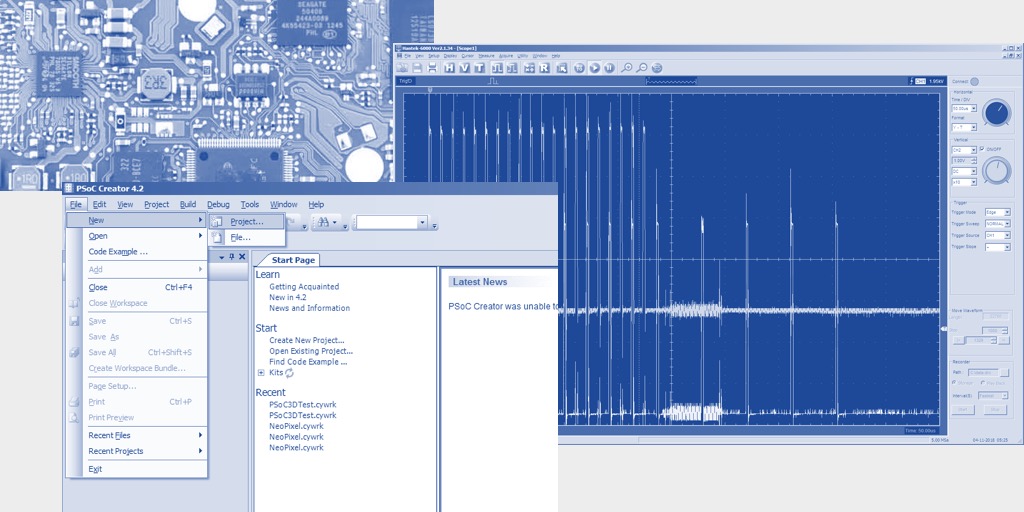
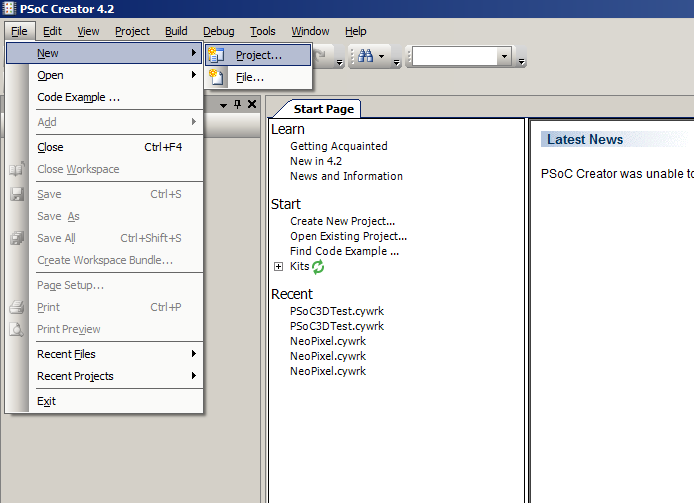
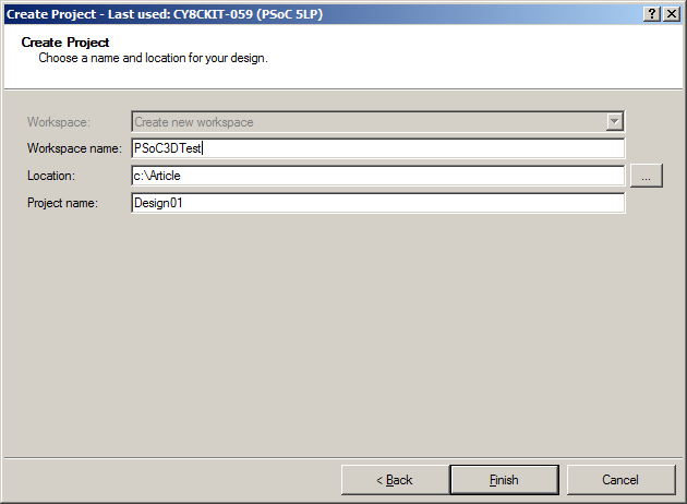
Good. Enough of a boring theory! Go to practice! We start PSoC Creator and select File-> New-> Project:
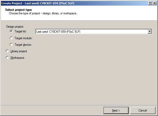
Next, I chose the layout I had, from which the environment would take basic information about the controller used and its settings:
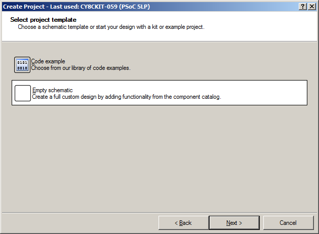
I already feel ready to create a project from scratch, so I choose Empty Schematic :
We give the working environment the name PSoC3DTest :
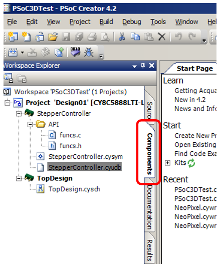
And here it is, the finished project!

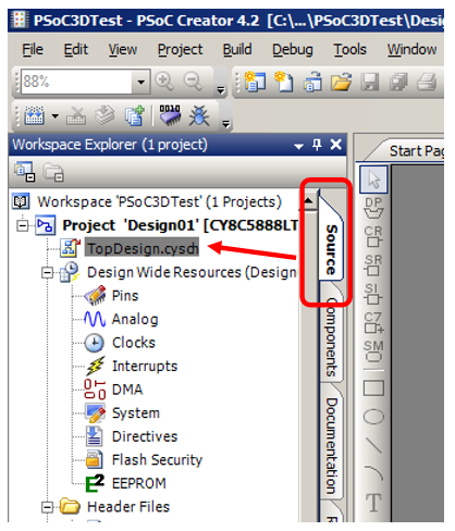
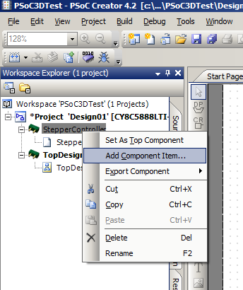
The first thing I want to do is create my own UDB-based component. Therefore, as noted in the last article, I need to switch to the Components tab :
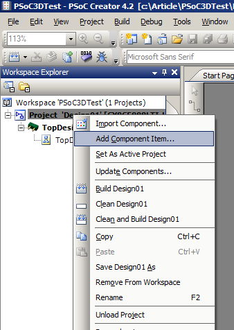
Right click on the project and select Add Component Item :
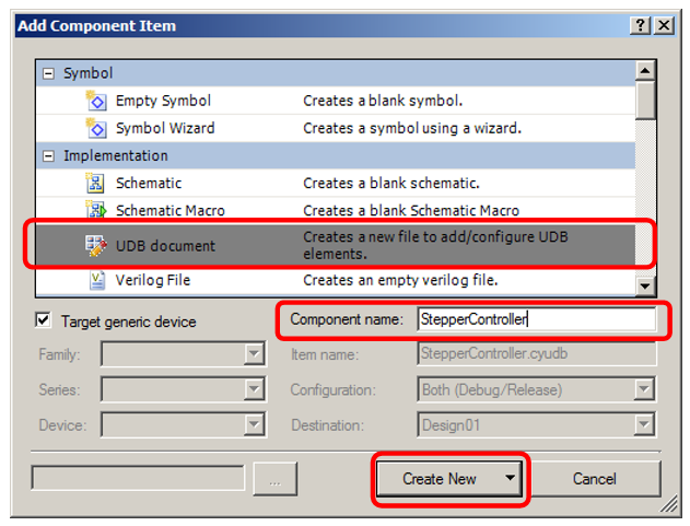
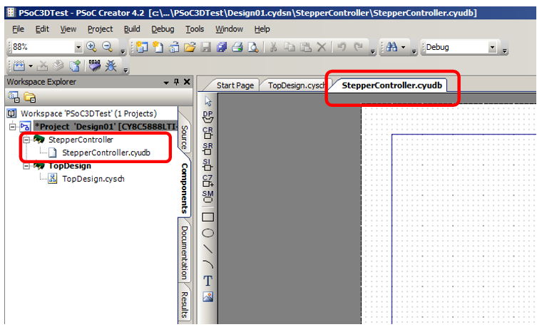
We say that we need to add a UDB Document , change the name to StepperController and click on Create New :
The component appears in the tree , plus - the editor of this component has opened:
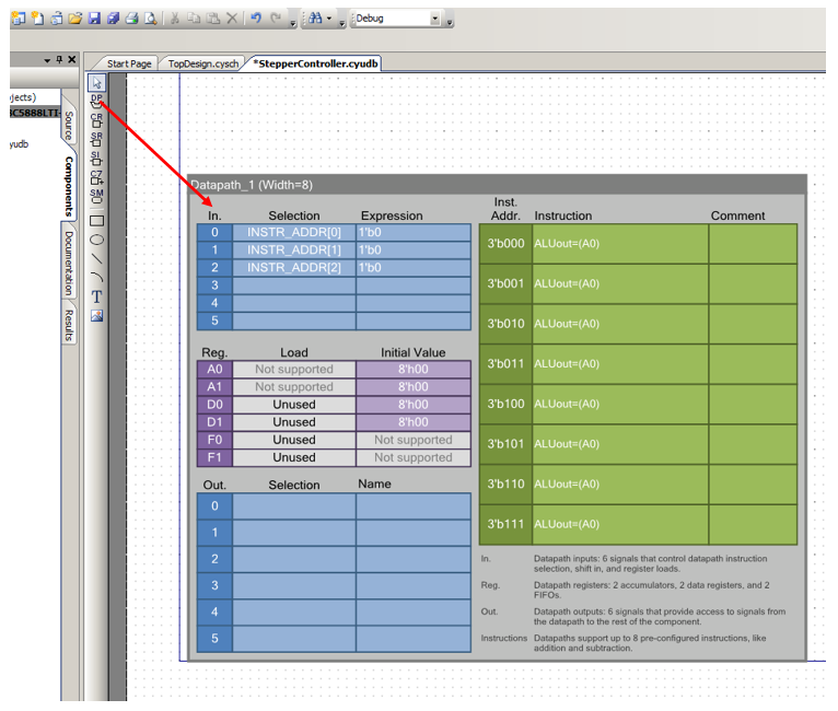
Place the Datapath block on the form:
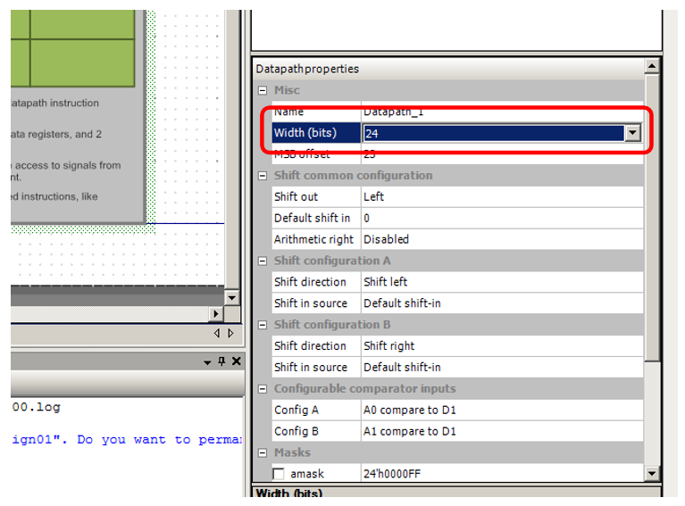
Selecting this block, go to its properties and change the bit width from 8 to 24. The remaining parameters can be left unchanged.
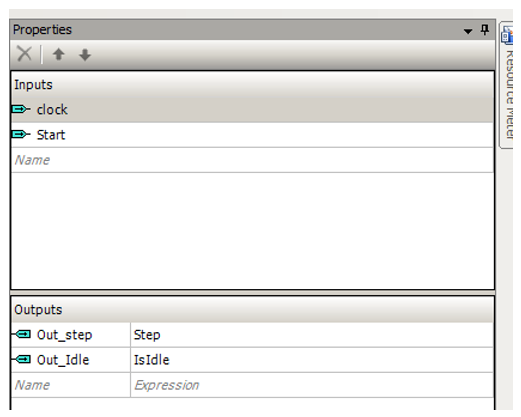
So that all the blocks (for all engines) start at the same time, I will start the start signal outside (I will add the Start input ). Outputs: I'll exit Step directly, in order to be able to submit it to the driver for the stepping motor, as well as Out_Idle . On this signal, the processor will be able to determine that at the moment the unit has finished its work. The names of the circuits matching these inputs and outputs are visible in the figure.
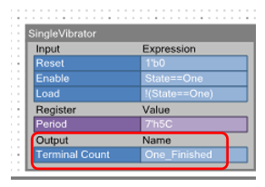
Before talking about the logic of the automaton, I will describe one more purely engineering problem: setting the pulse width Step. The documentation for the DRV8825 driver requires that the width of this pulse be at least 1.9 µs. Other drivers are less demanding on its width. As already noted in the theoretical part, the existing registers are already occupied by specifying the step duration and the number of steps. Whatever one may say, a seven-bit counter should be placed on the circuit. We call it the one-shot, which sets the step pulse. With a frequency of 48 MHz to ensure a duration of 1.9 μs, this counter must count at least 91.2 steps. Round up to 92. Any value greater than this will be no less. The following setting is obtained:
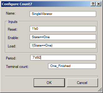
The name of the counter is SingleVibrator . He never reset, so the input Resetalways connected to zero, it considers when the automaton (described below) is in the One state, it is loaded in all other states (at first I selected the specific states of the automaton, but it turned out that with this clever method, much less PLD resources are required, but the result is the same). The load value is equal to decimal 92. However, a good editor will immediately replace this value with a hexadecimal value:
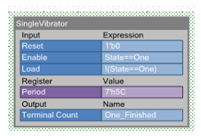
When the counter has counted to zero, it will report this to the chain with the name One_Finished . With the counter - everything.
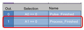
What our machine will need status flags? I did it like this (remember, to set them up, you need to double-click on the list of outputs in Datapath):
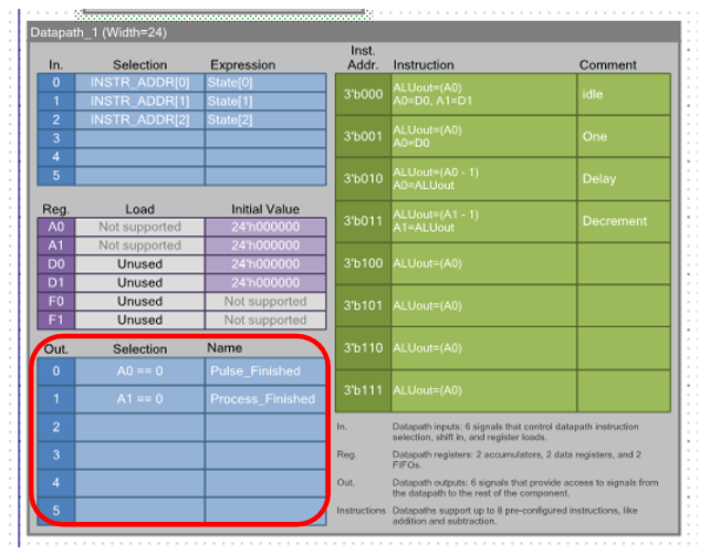

I will use the battery A0 as a pulse width counter, so when its value reaches zero, the flag will be coded, which I named Pulse_Finished . Battery A1 I will count pulses. Therefore, its zeroing will cock the Process_Finished flag .
We build the transition graph of the automaton: The
variable that sets its state is called State . We immediately assign this variable to the address of the instruction address of the ALU. I first forgot to do it, so for a long time I could not understand why my machine does not work. Double click on the block of inputs in Datapath:
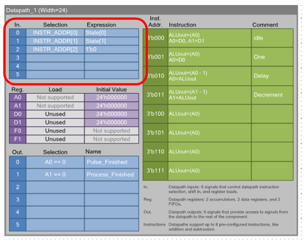
And we match:

We start to deal with the transition graph and the associated ALU instructions.
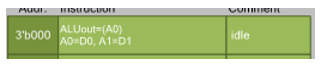
Let's start with the stateThe Idle . It is quite saturated in its actions.
First, the value of data registers D0 and D1 is constantly placed in batteries A0 and A1, respectively:
From this record, the keen eye will see everything that is necessary. Since we still do not have an eye for the eye, double click on the record and see the same, but in more detail:
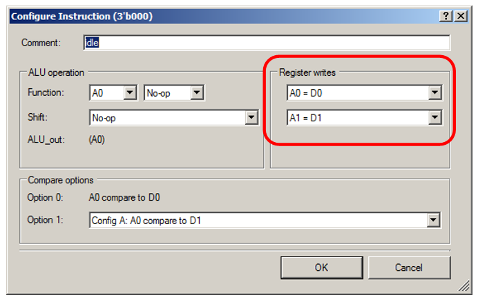
The main value here is filling the battery A1, the pulse counter. When the program enters the value of D1, it will immediately fall into A1. The program will not have time to start the process until the next clock cycle. This value is checked to form an exit condition out of this state, that is, it cannot be filled anywhere else.
Now we look at what is being done at the level of the transition graph:
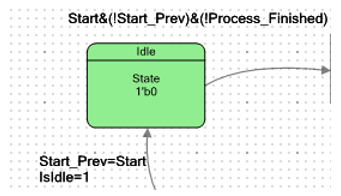
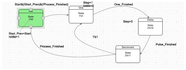
Auxiliary trigger Start_Prevallows you to catch a positive differential at the Start input by organizing a delay line for 1 clock cycle. It will always be the state of the Start input , which was on the previous clock. Some people are more accustomed to see this in Verilog:
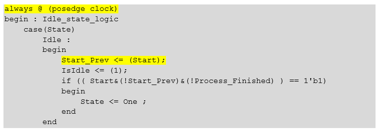
Same text
always @ (posedge clock)
begin : Idle_state_logic
    case(State)
        Idle :
        begin
            Start_Prev <= (Start);
            IsIdle <= (1);
            if (( Start&(!Start_Prev)&(!Process_Finished) ) == 1'b1)
            begin
                State <= One ;
            end
        end
Accordingly, the condition Start & (! Start_Prev) is true only when a positive drop of the Start line occurred between the bars .
In addition, when the machine is in this state, the IsIdle output translates to a single state, informing the external environment that the unit is passive. With this approach, fewer PLD resources are spent than if the output is a State == Idle construct .
When a drop in the Start signal comes from the external environment , and a non-zero value is found in the battery A1, the machine will exit the Idle state . If zero is entered in A1, the engine does not participate in the development of this segment, so that the difference in the Start lineignored. This applies to an unused extruder. For a number of printers, the engine is also quite rarely used along the Z axis. Let me remind you how a condition is formed that detects a zero value in A1 (and a nonzero value is its inversion):
Next, the machine enters the One state :
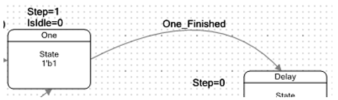
In this state, the output Step is set to 1. On The driver is given a stepping pulse. In addition, the IsIdle trigger value is reset . The external environment is informed that the block is in the active phase.
The exit from this state is made by the One_Finished signal , which will be cocked into a unit when the seven-bit counter counts to zero. Let me remind you that the One_Finished signal is generated by this counter:
While the machine is in this state, the ALU loads into the battery A0 (defining the pulse duration) the value from the register D0. Let me show you only a brief record of this: The

loaded value will be used in the following state. Being in it, the machine generates a delay, which sets the pulse duration: Step
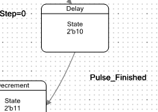
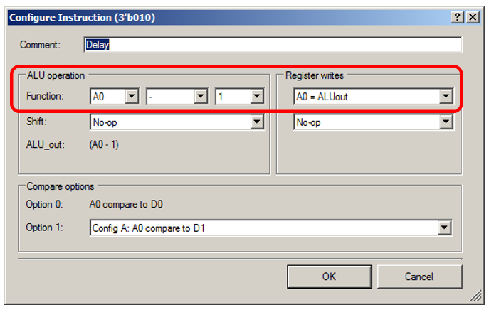
output is reset to zero. The battery A0 decreases, as evidenced by the following brief entry: And if you double-click on it - the complete entry: When A0 reaches zero, the Pules_Finished flag is on, and the machine goes into Decrement state : In this state, the value of the A1 setting the number decreases in the ALU Pulses: Full version of the recording:

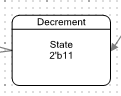
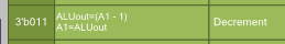
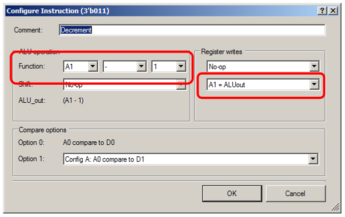
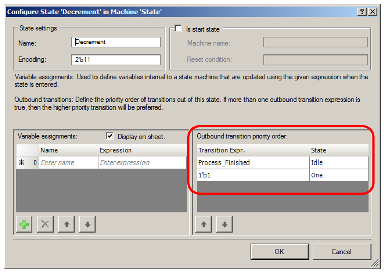
Depending on the result, a transition occurs either to the next pulse or to the Idle state . Double click on the state to see the transitions taking into account priorities:
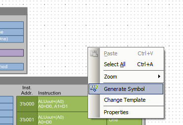
Actually, everything is with UDB. Now we make the corresponding symbol. To do this, right-click on the editor and select Generate Symbol :
Go to the project diagram:
And we introduce a circuit in which there are a certain number of these controllers. I chose five (three axes plus two extruders). Printers with a large number of extruders will not be considered cheap. They can and FPGA put. Along the way, to see the real complexity, I threw a USB-UART block (to receive data from a computer or the same Raspberry Pi) and a real UART (it will provide communication with a cheap Wi-Fi module ESP8266 or, say, an intelligent display that can send GCODE via UART). Shimmy and others did not add, since their complexity is approximately clear, but to the real system is still far away. It turned out something like this:
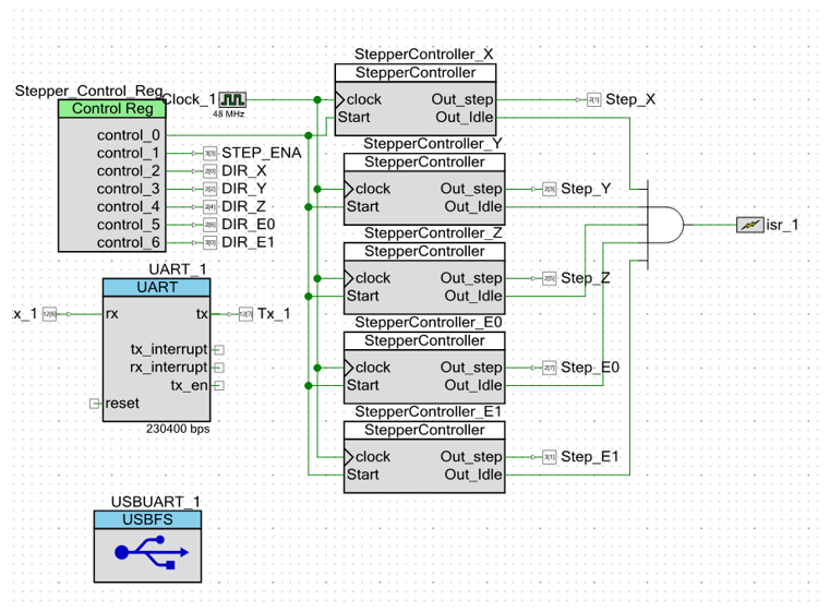
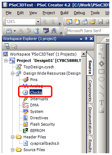
The control register generates a start signal that goes to all the blocks at the same time. In addition, the signals that are static during the formation of the segment are allowed to come out of it. All Idle OutsI collected the "and" and served on the interrupt input. Interruption I appointed on the positive front. If at least one engine has started operation, the interrupt input will be reset. At the end of the last engine, it will be cocked, which will inform the processor of readiness for the next segment. We will now configure the frequency of double-clicking on an element of the tree Clocks :
In the table twice scholknem the element PLL_OUT :
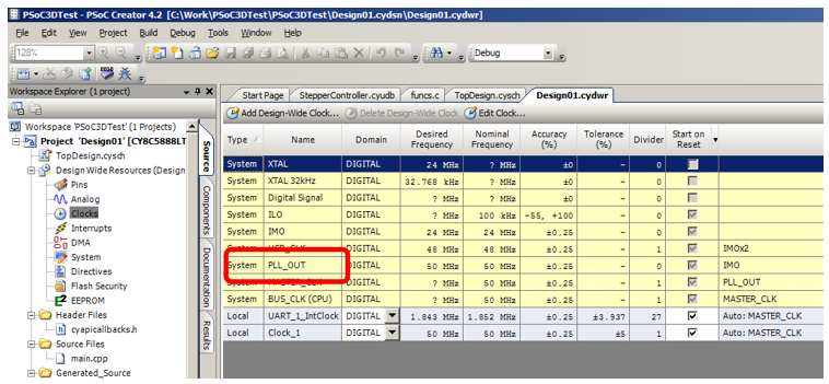
Fill in the table something like this (I'm still not well understood the rules of setting the table, why use the term "Somehow"):
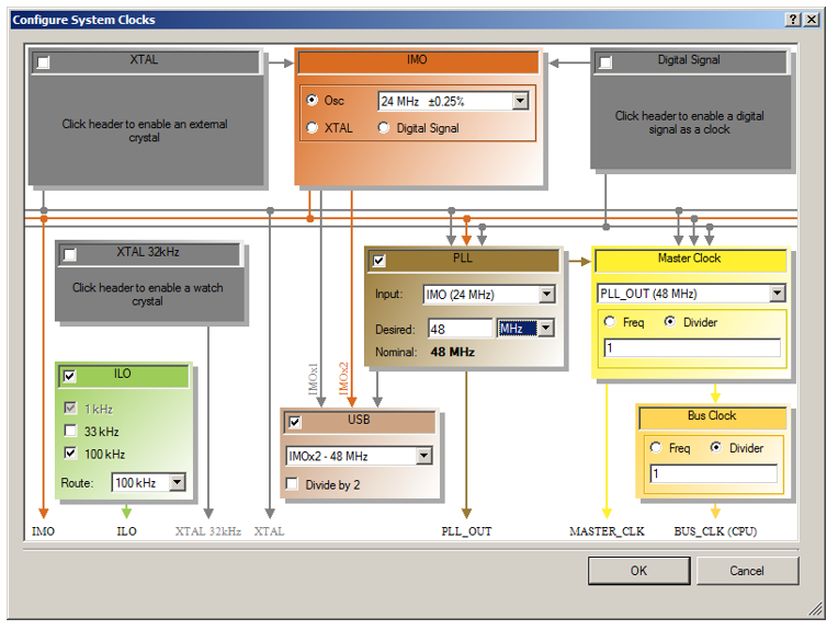
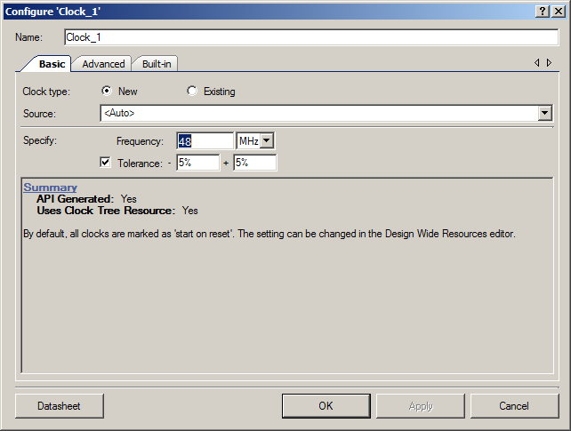
Now Double-click on the line Clock_1 : Set
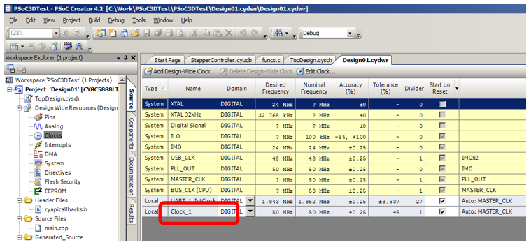
the clock frequency of the UDB blocks to 48 MHz:
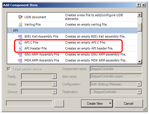
Since the project is experimental, there is no point in making an API to it. But to consolidate the material studied in the last article, go back to the Components tab and for the StepperController project, right-click through Add Component Item and first add the header file, and then the source code file C: I
’ll show you the two initialization and segment start functions that added. The rest can be seen in the example for the article.
void `$INSTANCE_NAME`_Start()
{
    `$INSTANCE_NAME`_SingleVibrator_Start();        //"One" Generator start
}
void `$INSTANCE_NAME`_PrepareStep(int nSteps,int duration)
{
    CY_SET_XTND_REG24(`$INSTANCE_NAME`_Datapath_1_D0_PTR, duration>92?duration-92:0);
    CY_SET_XTND_REG24(`$INSTANCE_NAME`_Datapath_1_D1_PTR, nSteps>1?nSteps-1:0);
}
I replaced the name of the main.c file with main.cpp to check that the development environment will normally respond to the use of C ++, since the Marlin “firmware” is object-oriented. Predictably showered with errors, which predictably were eliminated by adding a regular stuff:

Same text
extern "C"
{
    #include "project.h"
}
For the global engine launch, I made this function (it is very rough, but for experiments with a spherical horse in vacuum, it will come down; with experiments, the development time is more important than beauty):
void StartSteppers()
{
    Stepper_Control_Reg_Write (1);
    Stepper_Control_Reg_Write (1);
    Stepper_Control_Reg_Write (1);
    Stepper_Control_Reg_Write (0);
}
She cocks the Start signal , just in case, just three clock cycles, then drops it again.
Well, and proceed to the experiments. First, we simply step through the X and Y engines (in the example, the first group of calls initializes all the controllers, the second sets up the X and Y controllers for the required number of steps and starts the process):
int main(void)
{
    CyGlobalIntEnable; /* Enable global interrupts. */
    StepperController_X_Start();
    StepperController_Y_Start();
    StepperController_Z_Start();
    StepperController_E0_Start();
    StepperController_E1_Start();
    StepperController_X_PrepareStep (10,1000); // Задали параметры шагов
    StepperController_Y_PrepareStep (50,500);
    StartSteppers();    				// Запустили процесс
    for(;;)
    {
    }
}
We look at the result:
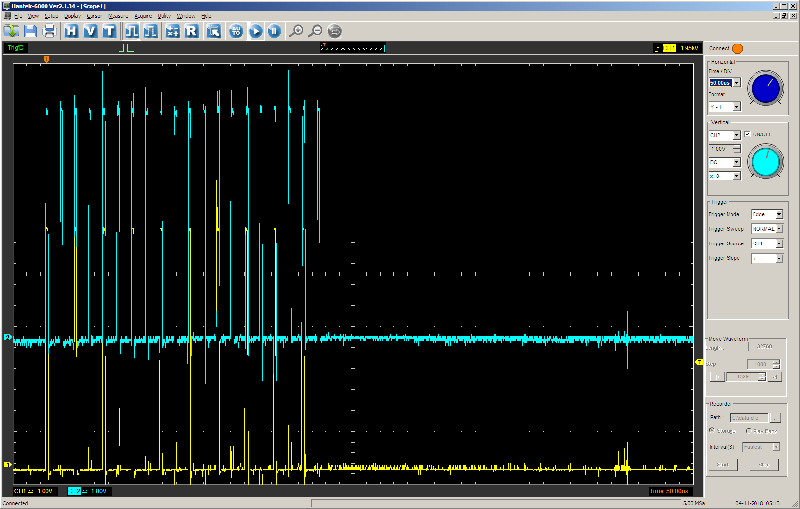
Check the duration of the positive impulse:

That's right. Finally, check how well the interrupt works. Add a global counter variable:
static int nStep=0;
This variable in the main function is assigned to one, and in the function of the interrupt handler increases. The interrupt handler will only work once, purely for verification. I made him like this:
extern "C"
{
    CY_ISR(StepperFinished)
    {
        if (nStep == 1)
        {
            StepperController_X_PrepareStep (5,500);
            StartSteppers();
            nStep += 1;
        }
    }
}
And I added literally two lines to the main function : enabling interrupts and assigning this variable itself. And I assign already, when the machines started. Otherwise, a false interrupt request arrived. To fight with him now there is no special reason. The project is experimental.
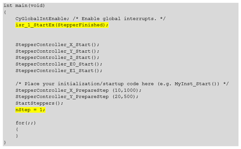
Same text
int main(void)
{
    CyGlobalIntEnable; /* Enable global interrupts. */
    isr_1_StartEx(StepperFinished);
    StepperController_X_Start();
    StepperController_Y_Start();
    StepperController_Z_Start();
    StepperController_E0_Start();
    StepperController_E1_Start();
    /* Place your initialization/startup code here (e.g. MyInst_Start()) */
    StepperController_X_PrepareStep (10,1000);
    StepperController_Y_PrepareStep (20,500);
    StartSteppers();
    nStep = 1;
    for(;;)
    {
    }
}
Checking the result (in the second step, only the X engine should work, and the steps should be twice as rare):
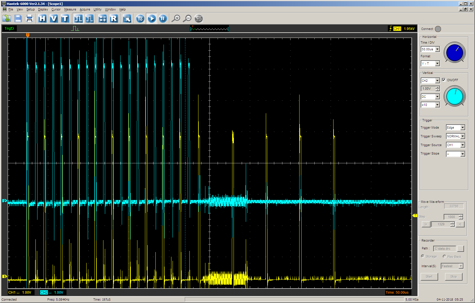
That's right.
Conclusion
In general, it is already clear that the UDB blocks can be used not only to define fast hardware functions, but also to remove logic from the software to the firmware level. Unfortunately, the volume of the article turned out to be so large that it is not possible to finish the review and get an unequivocal answer, whether there are enough UDB opportunities for the final solution of the task or not. So far, only a spherical horse in a vacuum is ready, whose actions are in principle very similar to those required, but a corrosive reader familiar with the theory of control of stepper motors will find a lot of flaws in it. The presented block does not support acceleration, without which the work of a real stepping motor is impossible. Or rather, it supports, but at this stage a high interrupt rate will be required, and everything was intended to avoid it.
The accuracy of setting the frequency of the presented block is far from acceptable. In particular, it will provide a pulse frequency of 40,000 Hz with a divider of 1,200 and 3,996 Hz with a divider of 1201. Intermediate frequencies between these two values are unattainable on this unit.
Perhaps there are some other flaws in it. But eliminating them by checking whether there are enough resources for UDB will be dealt with in the next article.
In the meantime, readers have received, among other things, a real example of creating a block based on UDB from scratch. The test project, which turned out when writing this article, you can take here .