Building wireless networks of all sizes based on TP-Link equipment
Quite often there is a situation when it is required to organize seamless coverage of a large territory and establish control over a wireless network with a large number of access points. Let's talk about how to optimally implement the project: where to start, what parameters to consider, how to configure equipment and where the catch can wait. As a living example, take our Auranet lineup, which includes enterprise-class access points and network controllers.
At the first stage, it is necessary to determine what equipment and in what quantity will be needed to build the network. This is not only about controllers and access points. A wireless network cannot function without its wired infrastructure. Therefore, at this stage, it is worth taking into account the wire segments, since, most likely, they will have to be modernized.
How to determine if your existing wired infrastructure is suitable for your wireless network? First, access switches must have enough free ports for connecting wireless equipment. In addition, the modern IEEE 802.11N / AC standard network provides subscribers with quite high access speeds, which leads to stricter requirements for the speeds of wired interfaces, as well as the performance of the wired part of the network as a whole. For example, our CAP300 ceiling access point has a wired Fast Ethernet port (100 Mbps), while the CAP1750 has a gigabit network interface. Below we show what speeds can be available to users when connected to a CAP1750 access point.

Gigabit dual-band ceiling Wi-Fi access point, support for 802.11ac, CAP series, Auranet
TP-Link CAP1750
Secondly, to optimize the power supply scheme, modern access points can receive power not only from an external source, but also through a network cable using PoE technology (IEEE 802.3af or 802.3at depending on the model) - but for this to work, access switches must also support this technology.
Thirdly, access switches must be manageable and support work with virtual networks (VLANs), which is necessary when wireless equipment uses several SSIDs. Fortunately, almost all the switches used in the corporate segment can do this. Finally, you may have to make changes to the SCS - it depends on the total number of access points and their installation locations.
But how to understand how many access points you need to install? At a minimum, pay attention not only to the general plan of the premises, but also to the places of mass congestion of users, as well as to the number of people who can simultaneously use the communication in each of them. We already talked about this before - in the material devoted to building a wireless network in a hotel. At the same time, crowded places are not only conference rooms or office rooms for employees, but also shopping centers, educational institutions, hotel lounges, elevators, cafes and restaurants, patios, as well as other territories that are less obvious at first glance. In fact, competent radio-frequency reconnaissance is indispensable here. And here we have the opportunity to help our customers make radio planning and conduct a radio frequency survey, for which we have the appropriate hardware and software. However, a rough estimate of the number of access points depending on the density of users can be done immediately. The software limit for the CAP1750 access point is 200 wireless clients (100 for each radio band), but the recommended value is 50 wireless clients (25 for each radio band).

Do you need a controller if you have only a few access points? The answer to this question is a little more complicated than it might seem at first glance. The architecture of modern wireless networks has changed, and now a pair of access points will be enough only for a very small network. Previously, on each section of the network, coverage was provided by one access point with a transmitter at maximum power. In modern networks, it is recommended to perform the distributed installation of two or more access points, the transmitters of which are not used at full capacity. This architecture allows you to fully utilize the wired infrastructure, as well as to achieve higher speeds for connecting clients through the use of complex modulations, available only with a close mutual location of the access point and the wireless client.
The modern wireless network architecture also provides additional insurance in case of equipment breakdowns: if one access point fails, its functions will be temporarily taken over by neighboring wireless devices, which would not have been possible if it had been responsible for the site alone.
Using the 5 GHz band allows you to offload the problem frequency of 2.4 GHz, however, a higher frequency signal is more strongly absorbed by various obstacles located between the receiver and the transmitter, which in some cases significantly reduces the coverage area of the network operating at 5 GHz, and again brings us to the need to increase the grouping of access points at the facility.
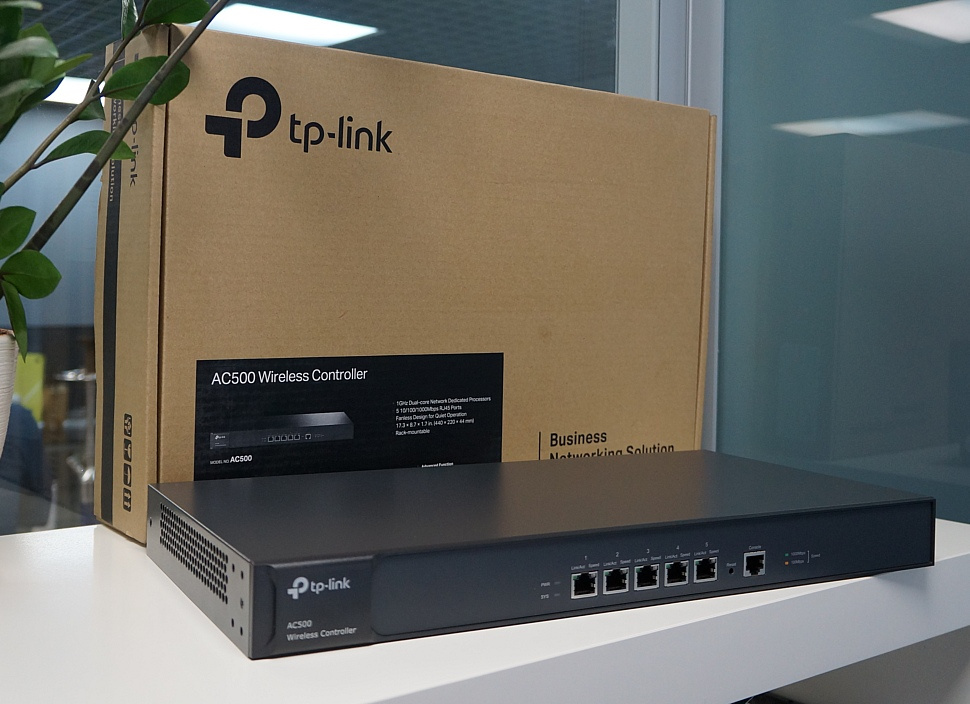
Here we will not describe in detail all the features of all menu items on the web interfaces of TP-Link wireless controllers. Instead, we will go through the entire initial setup process for the AC500 when adding a controller to an existing network. TP-Link AC500
wireless network controller CAP series, Auranet line For
those who want to learn more about the possibilities offered by the controller’s web interface, we recommend using the emulator available on our website .
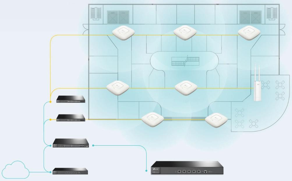
The procedure for deploying a wireless network is quite transparent and consists of several simple steps. It’s worth starting with preparing the network infrastructure for the implementation of the wireless segment. For definiteness, we will consider that it is necessary to provide wireless coverage at an object that is one building or a group of closely located buildings connected by a local network. Wireless equipment TP-Link has the ability to remotely connect access points to the controller, however, for simplicity, we assume that all connections are made within the same local network.
We decided to complicate the task of pilot implementation somewhat and use the existing wired infrastructure built on the basis of equipment from another manufacturer, as well as place the controller and access points in different subnets.
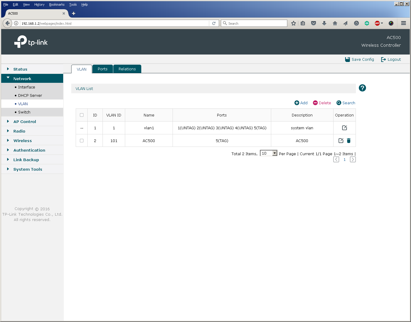
A virtual network VLAN 101 was created on the L3 switch to connect the AC500 controller. Using the fifth interface, the controller is connected to the switch's Gi0 / 6 port, which is configured in trunk mode. A virtual L3 interface (SVI) was created for routing.
switch3560 # sho vla bri
VLAN Name Status Ports
- - - - 1 default active Gi0 / 7
101 AC500 active
1002 fddi-default act / unsup
1003 trcrf-default act / unsup
1004 fddinet-default act / unsup
1005 trbrf-default act / unsup
switch3560 # sho run int vla 101
Building configuration ...
Current configuration: 108 bytes
!
interface Vlan101
description TP-LINK AC500
ip address 192.168.1.1 255.255.255.0
load-interval 30
end
switch3560 # sho run int gi0 / 6
Building configuration ...
Current configuration: 164 bytes
!
interface GigabitEthernet0 / 6
description AC500
switchport trunk encapsulation dot1q
switchport mode trunk
load-interval 30
spanning-tree portfast trunk
end
Now you need to configure the wireless controller itself: also create a VLAN 101 and configure the corresponding L3 interface. The fifth physical port of the controller should work in trunk mode.
In principle, the switch port for connecting the controller can be configured in access mode, however, then the controller can only route (not switch) user traffic for those access points that transmit it through it to the "large network". But more on that later.
To connect access points, we create VLAN 102, in which their management interfaces will be located. Switch ports are also configured in trunk mode.
switch3560 # sho vla bri
VLAN Name Status Ports
- - - - 1 default active
101 AC500 active
102 CAP1750 active Gi0 / 7
1002 fddi-default act / unsup
1003 trcrf-default act / unsup
1004 fddinet-default act / unsup
1005 trbrf-default act / unsup
switch3560 # sho run int gi0 / 7
Building configuration ...
Current configuration: 159 bytes
!
interface GigabitEthernet0 / 7
description TP-Link CAP1750
switchport access vlan 102
switchport trunk encapsulation dot1q
switchport trunk native vlan 102
switchport trunk allowed vlan 1,101-103
switchport mode trunk
load-interval 30
spanning-tree portfast trunk
end
Perhaps you should pay attention to that in the 802.1Q trunk between the access points and the switch, VLAN 102 was installed as the native VLAN. This configuration is due to the fact that the access points send untagged control frames to the network. You must also make sure (and disable if necessary) that the switches do not tag frames for native VLAN.
switch3560 (config) #no vlan dot1q tag native
switch3560 # sho vlan dot1q tag native
dot1q native vlan tagging is disabled
No special configuration is required from the access point, just switch the device to FIT mode (activated by default) and connect it to the corresponding port on the switch.

The configuration of the L3 interface of the switch for the virtual network into which the access points are connected is similar to the one that has already been made for the controller network.
switch3560 # sho run int vla 102
Building configuration ...
Current configuration: 141 bytes
!
interface Vlan102
description TP-LINK CAP1750
ip address 192.168.2.1 255.255.255.0
load-interval 30
end
We decided to place a DHCP server for the wireless network segment on the L3 switch. You can use any third-party DHCP servers that support options 60 and 138.
switch3560 # sho run | sec dhcp pool
ip dhcp pool tp-link
network 192.168.2.0 255.255.255.0
default-router 192.168.2.1
dns-server 8.8.8.8 8.8.4.4
option 60 ascii TP-LINK
option 138 ip 192.168.1.2
switch3560 # sho ip dhcp snooping binding
MacAddress IpAddress Lease (sec) Type VLAN Interface
- --------------- ---------- ------------- - - --------------------
50: C7: BF: 85: E2: 30 192.168.2.2 86 105 dhcp-snooping 102 GigabitEthernet0 / 7
Total number of bindings: 1
When placing the access points and the controller in one virtual network, one could use a DHCP server built into the controller.
It’s good practice to bind each existing wireless network identifier to your own virtual network, that is, to set up a unique match between the SSID and VLAN. For simplicity, we will use only one SSID in this pilot project, so we only need to create one more VLAN 103.
switch3560 # sho vla bri
VLAN Name Status Ports
- - - - 1 default active
101 AC500 active
102 CAP1750 active
103 client active
1002 fddi -default act / unsup
1003 trcrf-default act / unsup
1004 fddinet-default act / unsup
1005 trbrf-default act / unsup
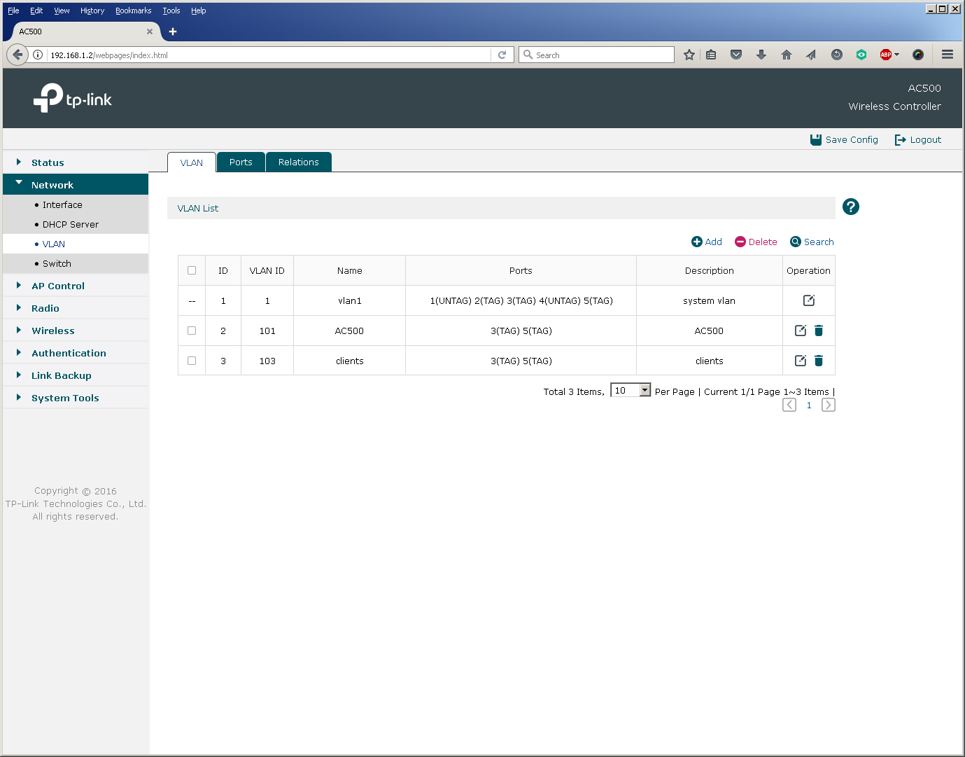
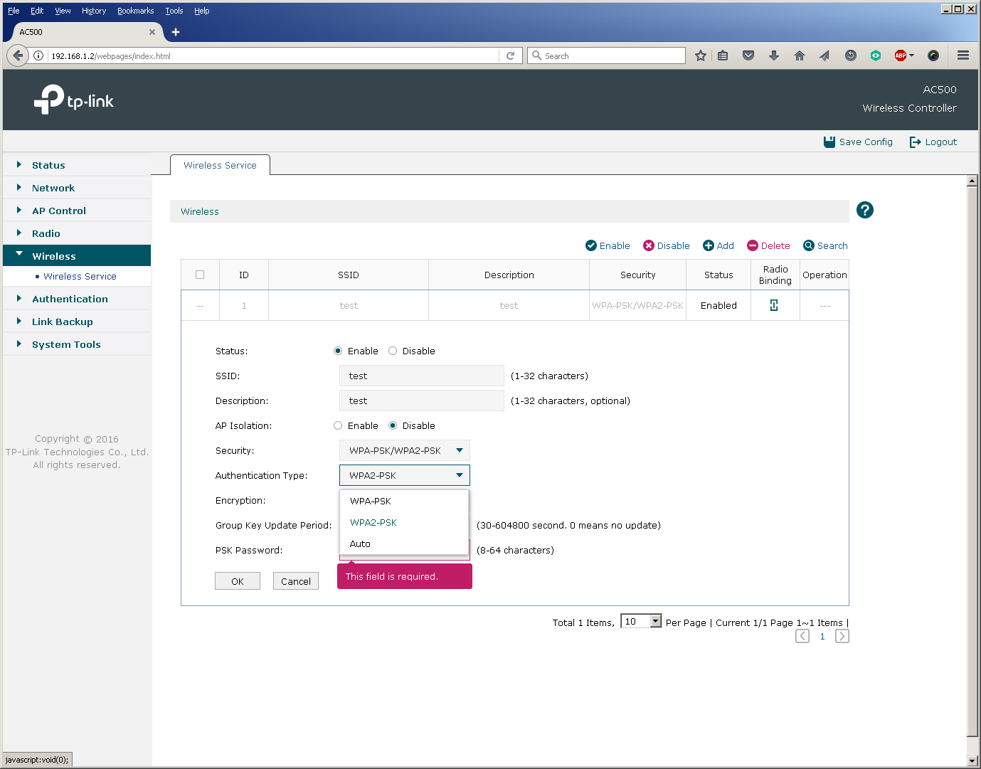
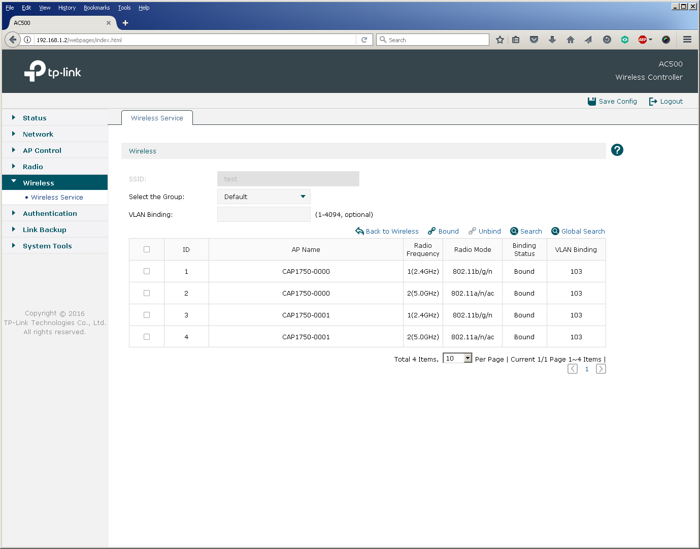
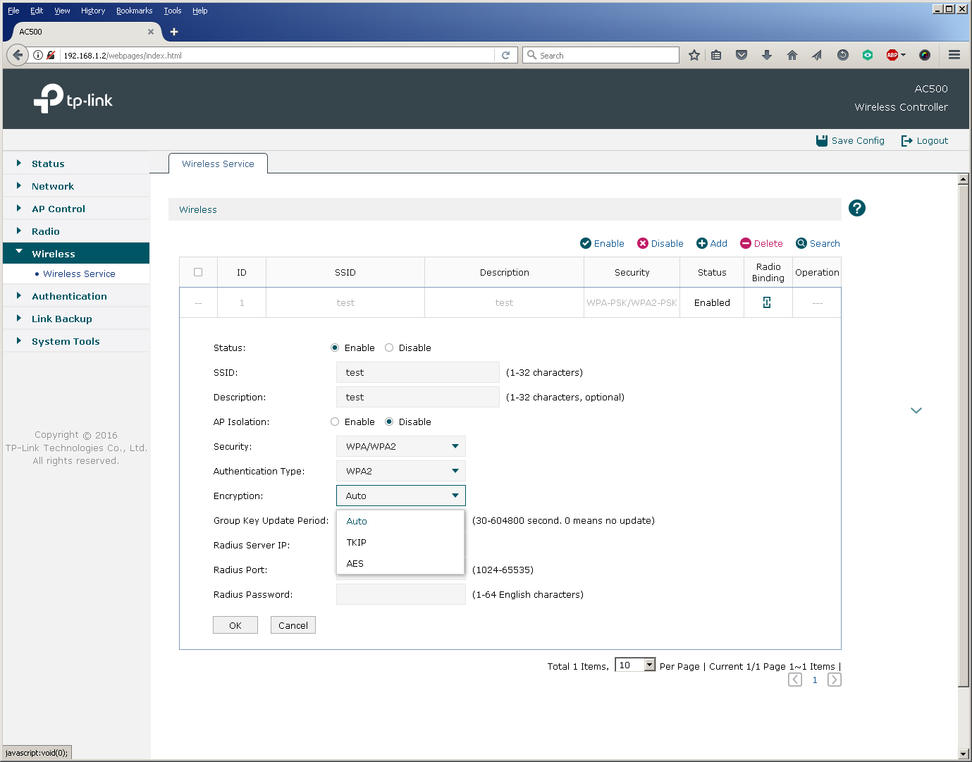
After the virtual network for client traffic has been created, you can proceed directly to the creation of a new wireless network and the binding of the SSID to the VLAN.

The basic setup of a new wireless network ends here, as already at that moment user devices can successfully connect to the network.
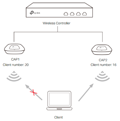
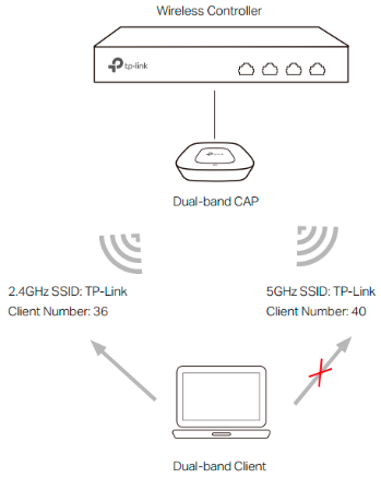
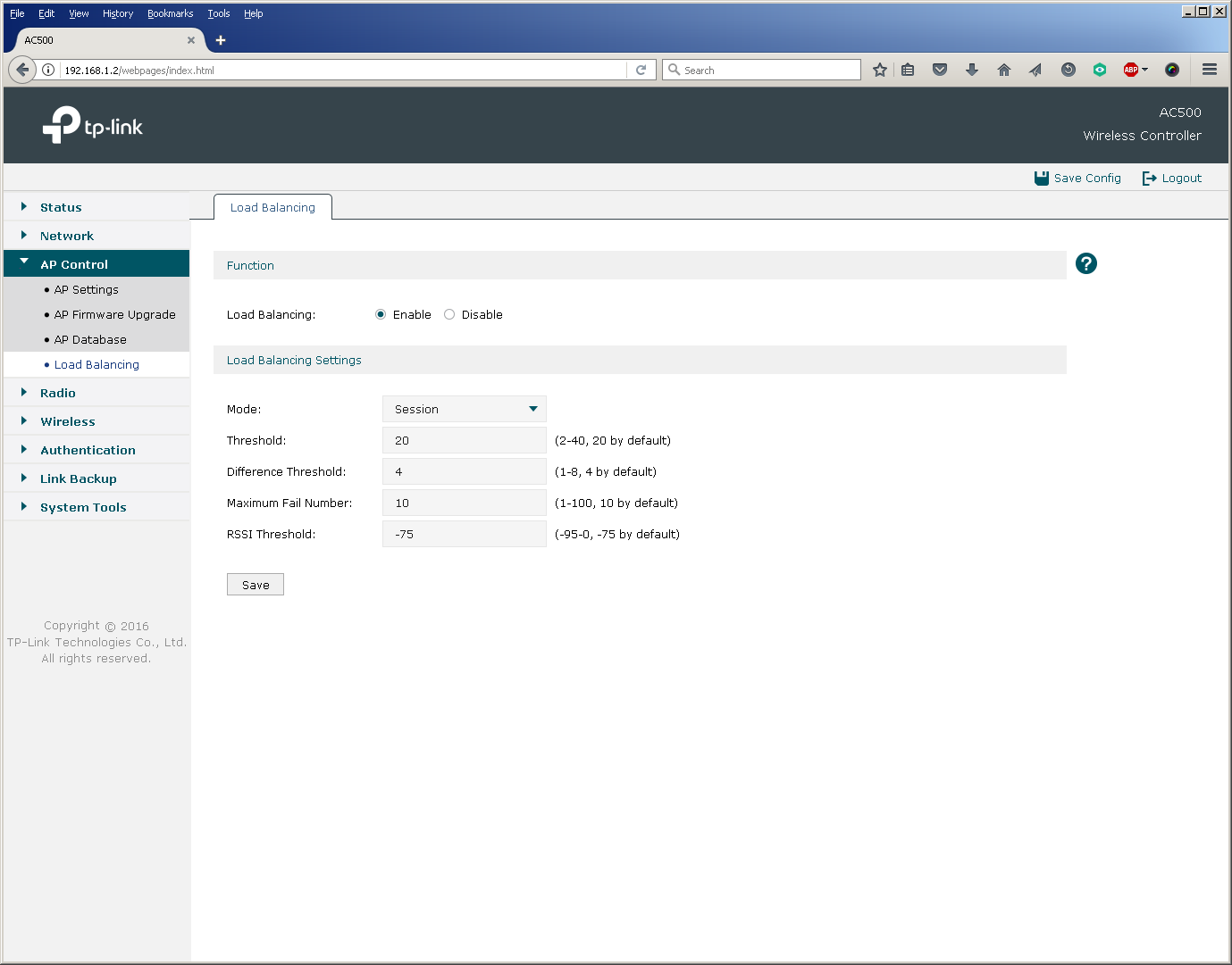
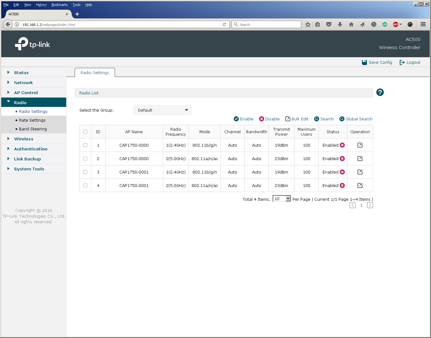
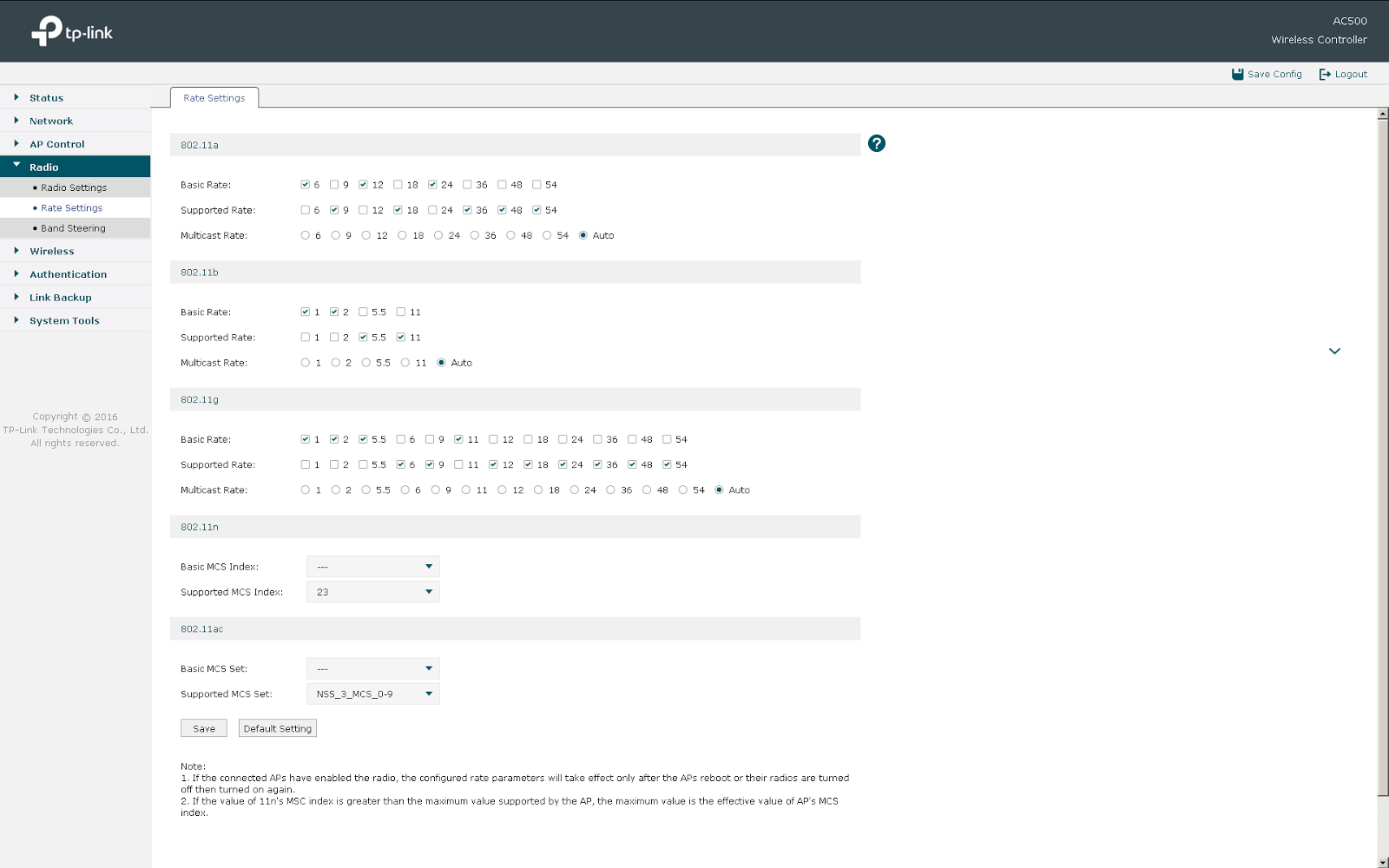
In addition to the main parameters, the administrator has access to fine-tuning and a number of auxiliary options. So, for example, you can change the settings for balancing users between access points and their redistribution between frequency ranges, as well as set the parameters of the wireless transmitters.
A wireless controller together with access points can not only request a secret key when connected to the network, but also perform additional user authentication using a RADIUS server.
In addition, users connecting to all or some SSIDs and gaining access to certain virtual networks can undergo additional authentication based on MAC addresses, web or Onekey.
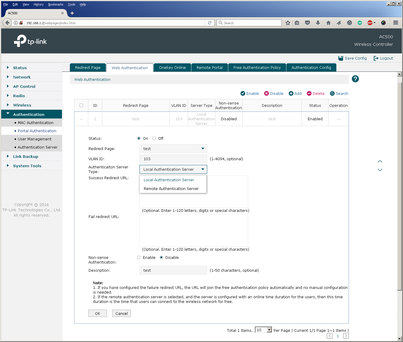
Perhaps one of the most common methods of additional authentication is web authentication, when a user is redirected to a special web page where you enter a username and password.
TP-Link AC50 / 500 wireless controllers allow web authentication based on a local list of users stored on the controller itself and using a remote RADIUS server.
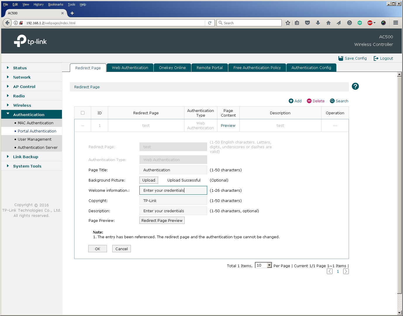
It should be noted that in the latest firmware version for the AC500 wireless controller, it was possible to log in via Facebook (Facebook Wi-Fi), as well as SMS-authorization using the twilio service.
Now consider the following models of wireless subscribers in the wired part of the network.
Depending on the relative position and settings of the wireless controller, access points and wired network segment, several typical patterns of user traffic movement are possible. They must be taken into account when designing a wireless network in order to avoid overload in the wired segment. It is worth noting here that at the moment, TP-Link wireless equipment does not encapsulate user data in the CAPWAP tunnel, that is, access points and controllers perform the so-called local switching, which leads to the need to either keep “stretched” VLANs on the network or use local VLANs with multiple IP subnets.
This model can usually be found in small wireless networks, where the number of access points is relatively small. Access points can be connected either directly to the ports of the wireless controller, or to auxiliary switches with or without PoE support.
Regardless of whether the controller commutes or routes user traffic, the link between the switch and the controller (Fast Ethernet for AC50 and Gigabit Ethernet for AC500) can be a bottleneck.
This model does not regulate the mutual arrangement of the wireless controller and access points in the network. The fundamental fact is such a configuration of network equipment and client devices, in which the controller acts as a default gateway for wireless clients. In this case, the link between the switch and the controller will also be overloaded.
This model is the most optimal in terms of performance, since the wireless controller is completely excluded from the transmission of user traffic. Access points essentially act as bridges by associating a wireless SSID with a VLAN in a wired segment. All further traffic processing is done by wired switches and routers.
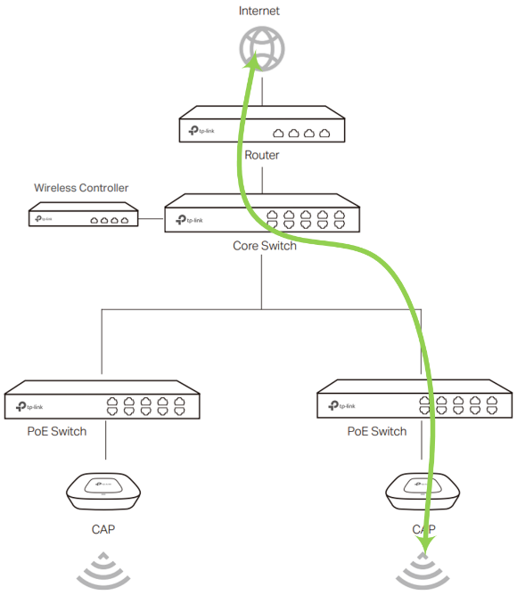
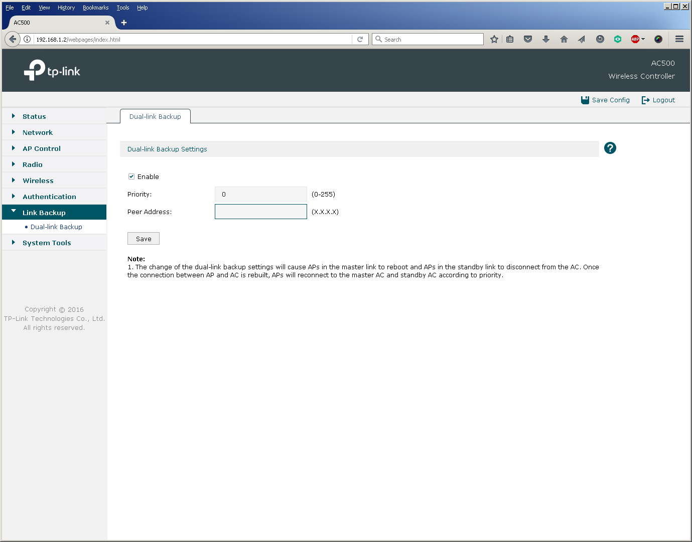
Apply this scheme optimally in large distributed networks with a large number of access points and wireless clients. It is also worth noting that TP-Link wireless controllers support the N + N redundancy function, working in a fault-tolerant pair.
We decided to slightly dilute the description of the controller's capabilities and how to connect it with a little testing in order to “live” show the operation of the device and access points.
The AC500 Wireless Controller is capable of routing traffic for two Gigabit Ethernet ports at medium speed in Full Duplex mode, making full use of the resources of both processor cores. Thus, with the AC500 as a router, users will be able to receive a total of 2 Gbit / s in large packets.
It should be noted that traffic switching is performed by the AC500 controller practically without using a central processor, which allows you to use all five Gigabit Ethernet ports in L2 mode at medium speed, while leaving the CPU resources free for other tasks.
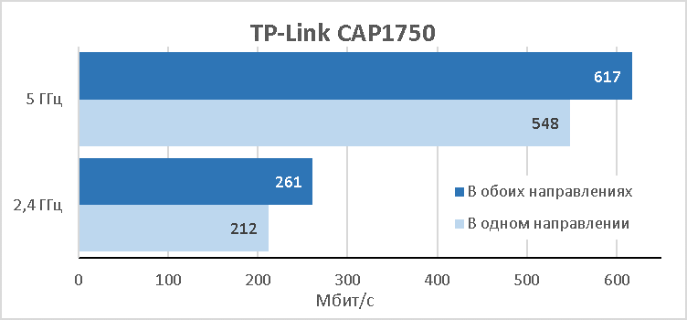
The CAP1750 access point provides users with a maximum theoretical speed of 450 Mbps in the 2.4 GHz band and 1.3 Gbit / s in the 5 GHz band. In practice, when using the CAP1750 model in the 2.4 GHz band, the total speed of simultaneous transmission of user data in both directions is about 260 Mbps. For the 5 GHz band, this value is 620 Mbps. We decided to present the results in a diagram.
The main characteristics of the test bench used for measurements are listed below. All measurements were made for 15 simultaneous TCP connections. The access point and the wireless client were located in close proximity to each other.
Thus, in practice, one CAP1750 access point will be able to transmit about 900 Mbps of traffic to the wired network when connecting wireless clients to both frequency ranges. The indicated speeds must be taken into account when building or updating a wireless network, possibly reducing over-subscription in the wired segment.
The wireless controller and access points are ready to work right out of the box, but we always strongly recommend updating the software preinstalled on the devices. The new firmware will not only correct detected inaccuracies in the code, but also add new features. For example, one of the most interesting innovations for our equipment will be support for cloud management, which allows centralized management of several wireless controllers at once. This option will be in demand in the case of very large or distributed objects. We are also implementing IPv6 protocol support, which will allow us to use our wireless equipment in next-generation IP networks. For network administrators, we have added support for SNMP, with the help of which there is the possibility of centralized device management and collection of statistics on the use of the controller and access points. As well as command line support.
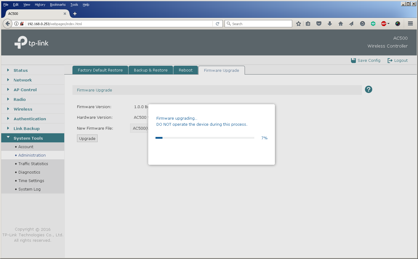
Software updates for any of our wireless controllers are done via the web interface. The whole process takes about five minutes and does not require any special knowledge from the user.
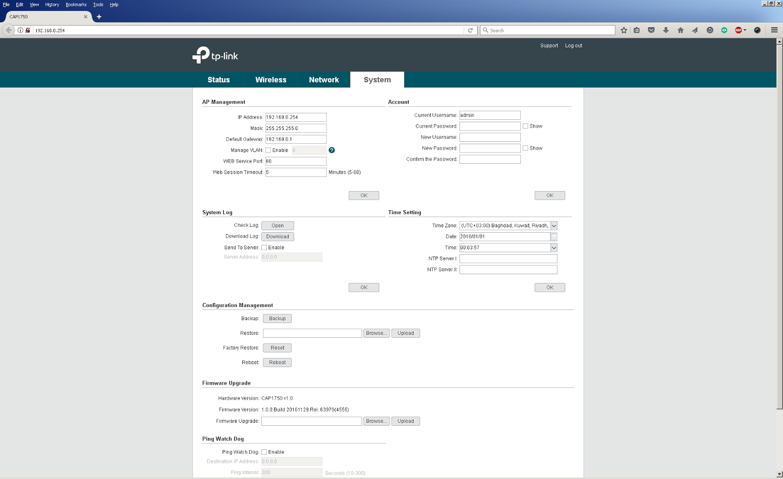
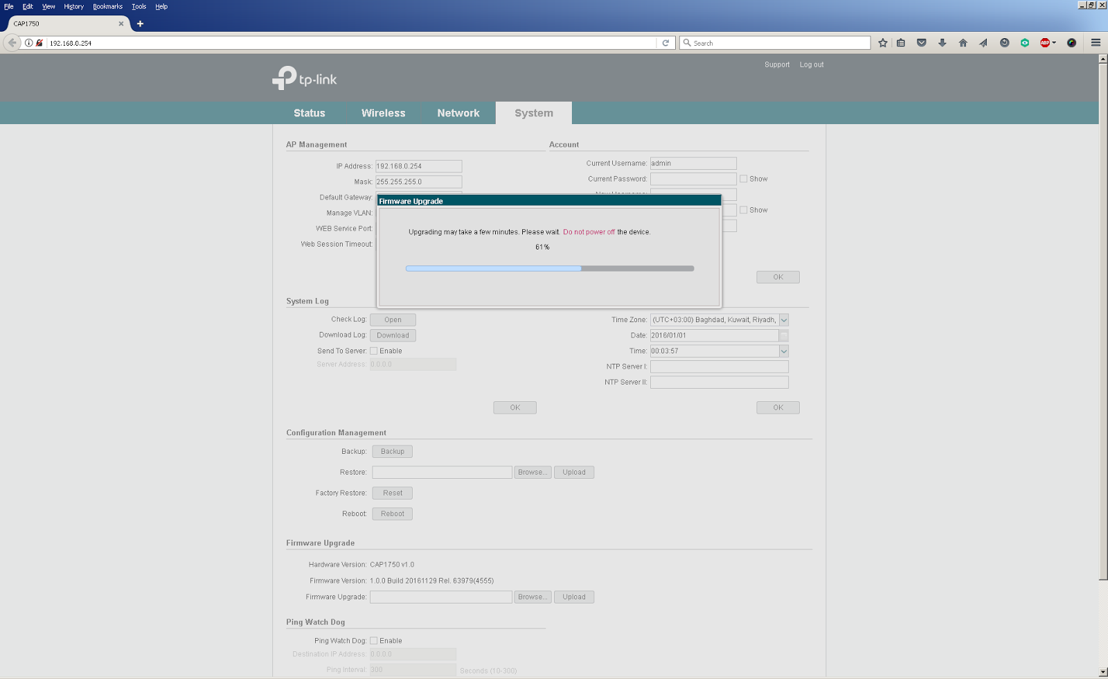
The way to replace firmware on access points depends on the mode in which they work: FIT or FAT. In FAT mode, the access point acts as a standalone device, so the firmware version is changed using the web interface of a specific device.
When building a wireless network on a large or complex facility, many wireless access points are needed to provide a continuous coverage zone. In this case, they are controlled (in FIT mode) using a wireless controller. To update their firmware it is also necessary to use a controller. The centralized change of firmware versions of access points is carried out using the controller’s web interface, where it is necessary to download a file containing the new firmware version, as well as indicate the start time of the update. You can also see a list of access points that it will affect.
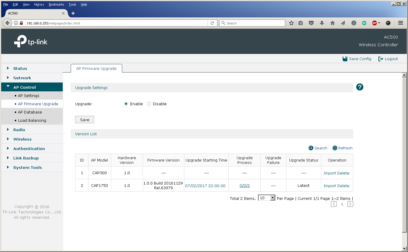
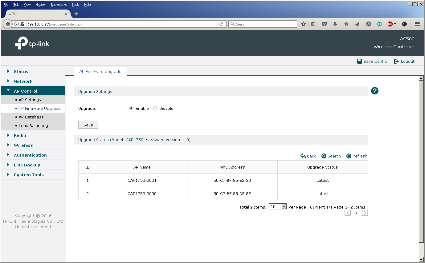
The possibility of a centralized update is especially useful for the AC500 wireless controller, since this model supports up to 500 access points at the same time, which makes manual replacement of firmware on an escorted object almost impossible.
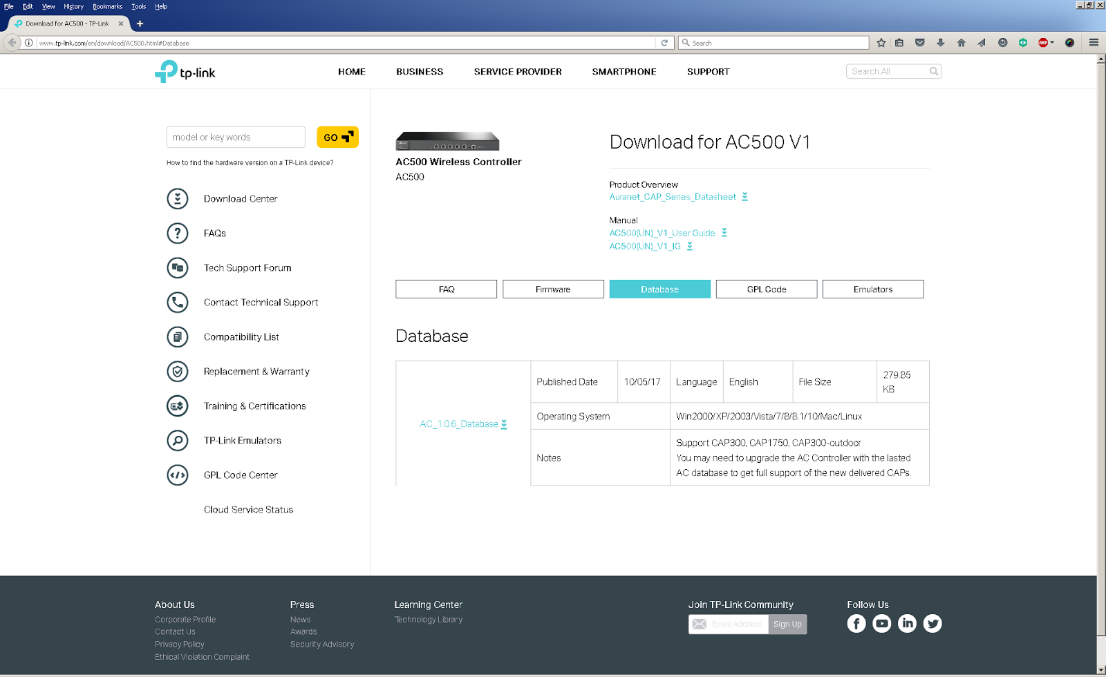
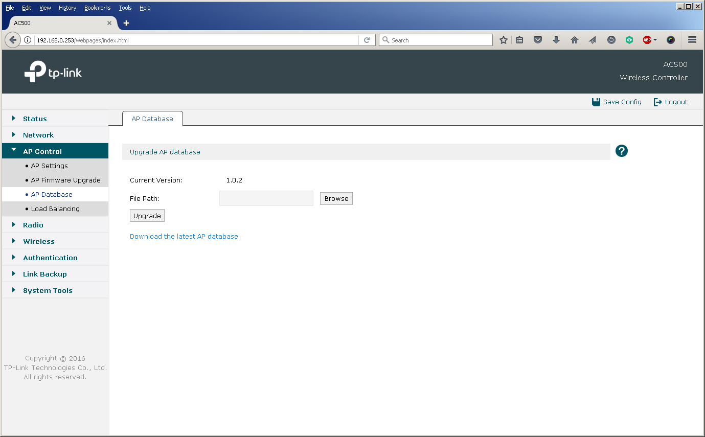
Since our range of equipment is constantly updated, after the release of a new model (for example, CAP1200), it is necessary to update the database of supported devices on the controller in order to expand the list of managed equipment.
As we showed above, the installation and configuration of TP-Link equipment is extremely simple, and a large number of modifiable parameters allows you to flexibly configure the network in accordance with all the wishes of the customer. Below we will list those key features of our products that we consider the most popular and relevant when building large-scale networks:
Equipment and topology selection
At the first stage, it is necessary to determine what equipment and in what quantity will be needed to build the network. This is not only about controllers and access points. A wireless network cannot function without its wired infrastructure. Therefore, at this stage, it is worth taking into account the wire segments, since, most likely, they will have to be modernized.
How to determine if your existing wired infrastructure is suitable for your wireless network? First, access switches must have enough free ports for connecting wireless equipment. In addition, the modern IEEE 802.11N / AC standard network provides subscribers with quite high access speeds, which leads to stricter requirements for the speeds of wired interfaces, as well as the performance of the wired part of the network as a whole. For example, our CAP300 ceiling access point has a wired Fast Ethernet port (100 Mbps), while the CAP1750 has a gigabit network interface. Below we show what speeds can be available to users when connected to a CAP1750 access point.
Gigabit dual-band ceiling Wi-Fi access point, support for 802.11ac, CAP series, Auranet
TP-Link CAP1750
Secondly, to optimize the power supply scheme, modern access points can receive power not only from an external source, but also through a network cable using PoE technology (IEEE 802.3af or 802.3at depending on the model) - but for this to work, access switches must also support this technology.
Thirdly, access switches must be manageable and support work with virtual networks (VLANs), which is necessary when wireless equipment uses several SSIDs. Fortunately, almost all the switches used in the corporate segment can do this. Finally, you may have to make changes to the SCS - it depends on the total number of access points and their installation locations.
But how to understand how many access points you need to install? At a minimum, pay attention not only to the general plan of the premises, but also to the places of mass congestion of users, as well as to the number of people who can simultaneously use the communication in each of them. We already talked about this before - in the material devoted to building a wireless network in a hotel. At the same time, crowded places are not only conference rooms or office rooms for employees, but also shopping centers, educational institutions, hotel lounges, elevators, cafes and restaurants, patios, as well as other territories that are less obvious at first glance. In fact, competent radio-frequency reconnaissance is indispensable here. And here we have the opportunity to help our customers make radio planning and conduct a radio frequency survey, for which we have the appropriate hardware and software. However, a rough estimate of the number of access points depending on the density of users can be done immediately. The software limit for the CAP1750 access point is 200 wireless clients (100 for each radio band), but the recommended value is 50 wireless clients (25 for each radio band).
When do I need a controller
Do you need a controller if you have only a few access points? The answer to this question is a little more complicated than it might seem at first glance. The architecture of modern wireless networks has changed, and now a pair of access points will be enough only for a very small network. Previously, on each section of the network, coverage was provided by one access point with a transmitter at maximum power. In modern networks, it is recommended to perform the distributed installation of two or more access points, the transmitters of which are not used at full capacity. This architecture allows you to fully utilize the wired infrastructure, as well as to achieve higher speeds for connecting clients through the use of complex modulations, available only with a close mutual location of the access point and the wireless client.
The modern wireless network architecture also provides additional insurance in case of equipment breakdowns: if one access point fails, its functions will be temporarily taken over by neighboring wireless devices, which would not have been possible if it had been responsible for the site alone.
Using the 5 GHz band allows you to offload the problem frequency of 2.4 GHz, however, a higher frequency signal is more strongly absorbed by various obstacles located between the receiver and the transmitter, which in some cases significantly reduces the coverage area of the network operating at 5 GHz, and again brings us to the need to increase the grouping of access points at the facility.
Controller Setup
Here we will not describe in detail all the features of all menu items on the web interfaces of TP-Link wireless controllers. Instead, we will go through the entire initial setup process for the AC500 when adding a controller to an existing network. TP-Link AC500
wireless network controller CAP series, Auranet line For
those who want to learn more about the possibilities offered by the controller’s web interface, we recommend using the emulator available on our website .
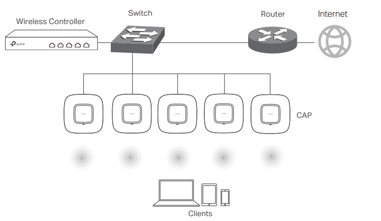
The procedure for deploying a wireless network is quite transparent and consists of several simple steps. It’s worth starting with preparing the network infrastructure for the implementation of the wireless segment. For definiteness, we will consider that it is necessary to provide wireless coverage at an object that is one building or a group of closely located buildings connected by a local network. Wireless equipment TP-Link has the ability to remotely connect access points to the controller, however, for simplicity, we assume that all connections are made within the same local network.
We decided to complicate the task of pilot implementation somewhat and use the existing wired infrastructure built on the basis of equipment from another manufacturer, as well as place the controller and access points in different subnets.
Presetting the wired part of the network (controller connection)
A virtual network VLAN 101 was created on the L3 switch to connect the AC500 controller. Using the fifth interface, the controller is connected to the switch's Gi0 / 6 port, which is configured in trunk mode. A virtual L3 interface (SVI) was created for routing.
switch3560 # sho vla bri
VLAN Name Status Ports
- - - - 1 default active Gi0 / 7
101 AC500 active
1002 fddi-default act / unsup
1003 trcrf-default act / unsup
1004 fddinet-default act / unsup
1005 trbrf-default act / unsup
switch3560 # sho run int vla 101
Building configuration ...
Current configuration: 108 bytes
!
interface Vlan101
description TP-LINK AC500
ip address 192.168.1.1 255.255.255.0
load-interval 30
end
switch3560 # sho run int gi0 / 6
Building configuration ...
Current configuration: 164 bytes
!
interface GigabitEthernet0 / 6
description AC500
switchport trunk encapsulation dot1q
switchport mode trunk
load-interval 30
spanning-tree portfast trunk
end
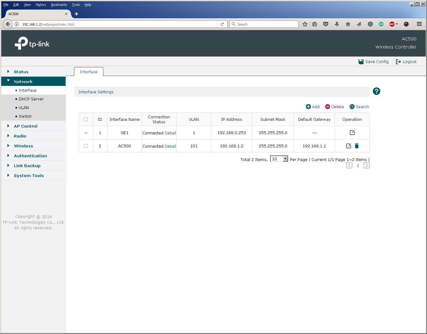
Now you need to configure the wireless controller itself: also create a VLAN 101 and configure the corresponding L3 interface. The fifth physical port of the controller should work in trunk mode.
In principle, the switch port for connecting the controller can be configured in access mode, however, then the controller can only route (not switch) user traffic for those access points that transmit it through it to the "large network". But more on that later.
Pre-setting the wired part of the network (connecting access points)
To connect access points, we create VLAN 102, in which their management interfaces will be located. Switch ports are also configured in trunk mode.
switch3560 # sho vla bri
VLAN Name Status Ports
- - - - 1 default active
101 AC500 active
102 CAP1750 active Gi0 / 7
1002 fddi-default act / unsup
1003 trcrf-default act / unsup
1004 fddinet-default act / unsup
1005 trbrf-default act / unsup
switch3560 # sho run int gi0 / 7
Building configuration ...
Current configuration: 159 bytes
!
interface GigabitEthernet0 / 7
description TP-Link CAP1750
switchport access vlan 102
switchport trunk encapsulation dot1q
switchport trunk native vlan 102
switchport trunk allowed vlan 1,101-103
switchport mode trunk
load-interval 30
spanning-tree portfast trunk
end
Perhaps you should pay attention to that in the 802.1Q trunk between the access points and the switch, VLAN 102 was installed as the native VLAN. This configuration is due to the fact that the access points send untagged control frames to the network. You must also make sure (and disable if necessary) that the switches do not tag frames for native VLAN.
switch3560 (config) #no vlan dot1q tag native
switch3560 # sho vlan dot1q tag native
dot1q native vlan tagging is disabled
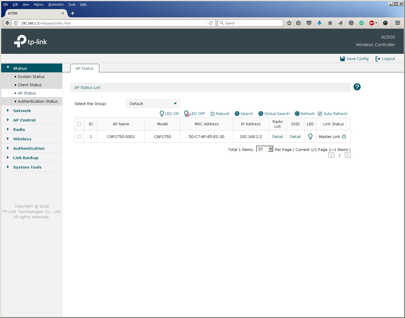
No special configuration is required from the access point, just switch the device to FIT mode (activated by default) and connect it to the corresponding port on the switch.
The configuration of the L3 interface of the switch for the virtual network into which the access points are connected is similar to the one that has already been made for the controller network.
switch3560 # sho run int vla 102
Building configuration ...
Current configuration: 141 bytes
!
interface Vlan102
description TP-LINK CAP1750
ip address 192.168.2.1 255.255.255.0
load-interval 30
end
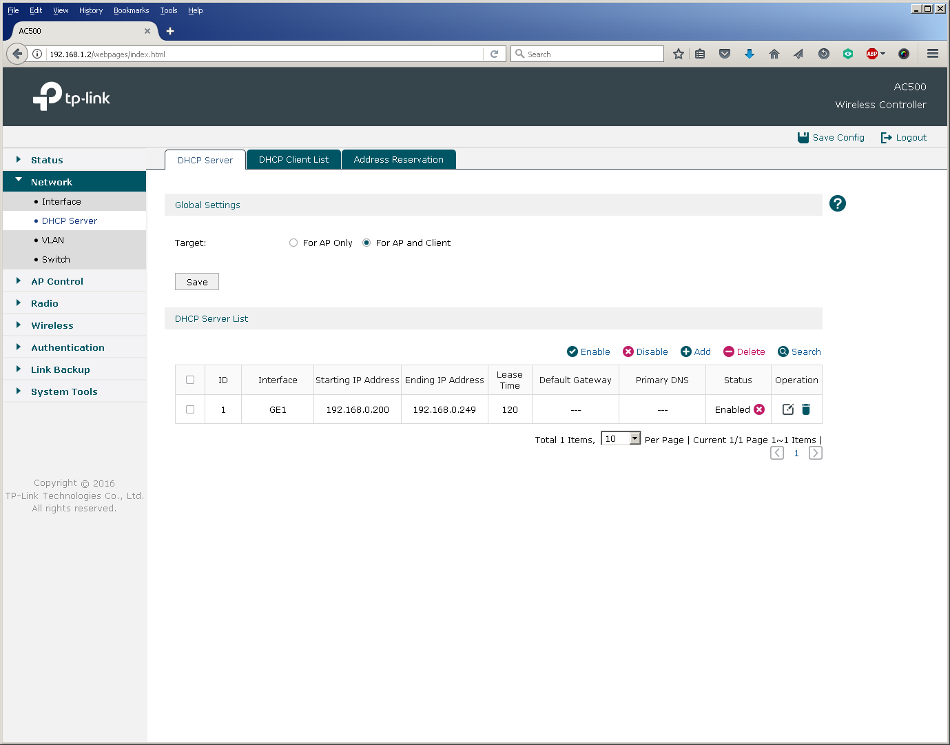
We decided to place a DHCP server for the wireless network segment on the L3 switch. You can use any third-party DHCP servers that support options 60 and 138.
switch3560 # sho run | sec dhcp pool
ip dhcp pool tp-link
network 192.168.2.0 255.255.255.0
default-router 192.168.2.1
dns-server 8.8.8.8 8.8.4.4
option 60 ascii TP-LINK
option 138 ip 192.168.1.2
switch3560 # sho ip dhcp snooping binding
MacAddress IpAddress Lease (sec) Type VLAN Interface
- --------------- ---------- ------------- - - --------------------
50: C7: BF: 85: E2: 30 192.168.2.2 86 105 dhcp-snooping 102 GigabitEthernet0 / 7
Total number of bindings: 1
When placing the access points and the controller in one virtual network, one could use a DHCP server built into the controller.
Managing Wireless Network Identifiers (SSIDs)
It’s good practice to bind each existing wireless network identifier to your own virtual network, that is, to set up a unique match between the SSID and VLAN. For simplicity, we will use only one SSID in this pilot project, so we only need to create one more VLAN 103.
switch3560 # sho vla bri
VLAN Name Status Ports
- - - - 1 default active
101 AC500 active
102 CAP1750 active
103 client active
1002 fddi -default act / unsup
1003 trcrf-default act / unsup
1004 fddinet-default act / unsup
1005 trbrf-default act / unsup
After the virtual network for client traffic has been created, you can proceed directly to the creation of a new wireless network and the binding of the SSID to the VLAN.
The basic setup of a new wireless network ends here, as already at that moment user devices can successfully connect to the network.
Configure auxiliary wireless settings
In addition to the main parameters, the administrator has access to fine-tuning and a number of auxiliary options. So, for example, you can change the settings for balancing users between access points and their redistribution between frequency ranges, as well as set the parameters of the wireless transmitters.
Authentication
A wireless controller together with access points can not only request a secret key when connected to the network, but also perform additional user authentication using a RADIUS server.
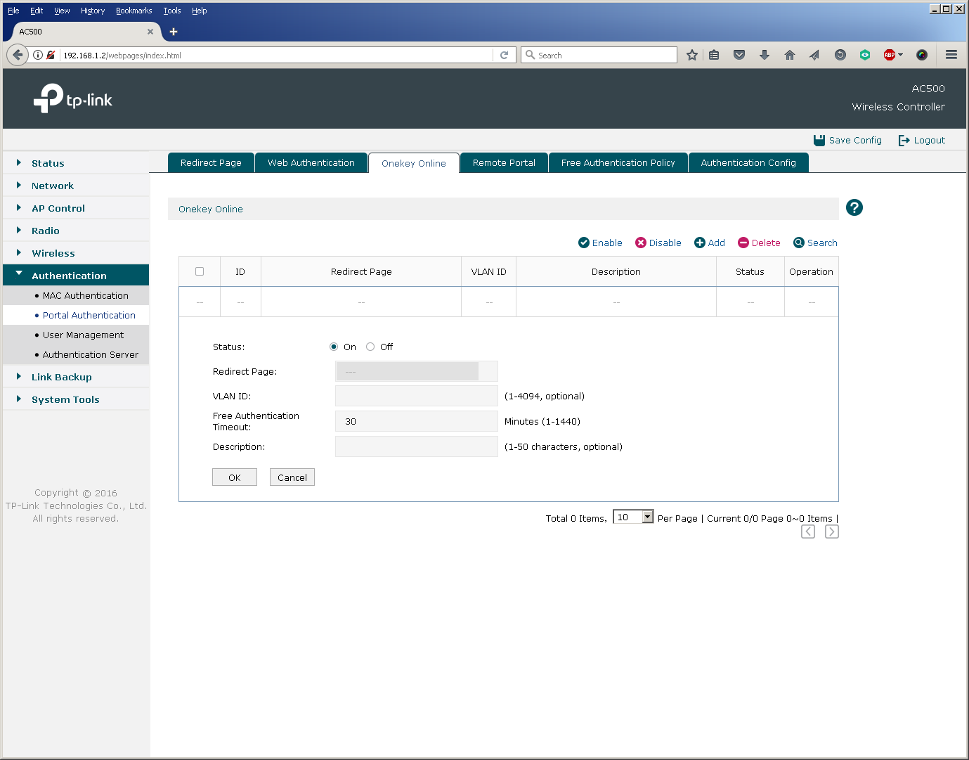
In addition, users connecting to all or some SSIDs and gaining access to certain virtual networks can undergo additional authentication based on MAC addresses, web or Onekey.
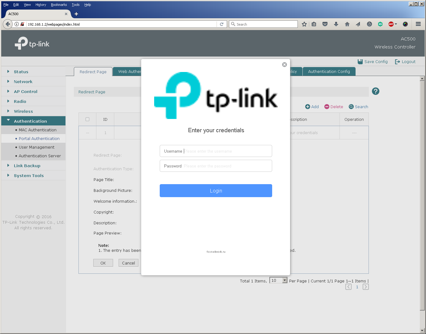
Perhaps one of the most common methods of additional authentication is web authentication, when a user is redirected to a special web page where you enter a username and password.
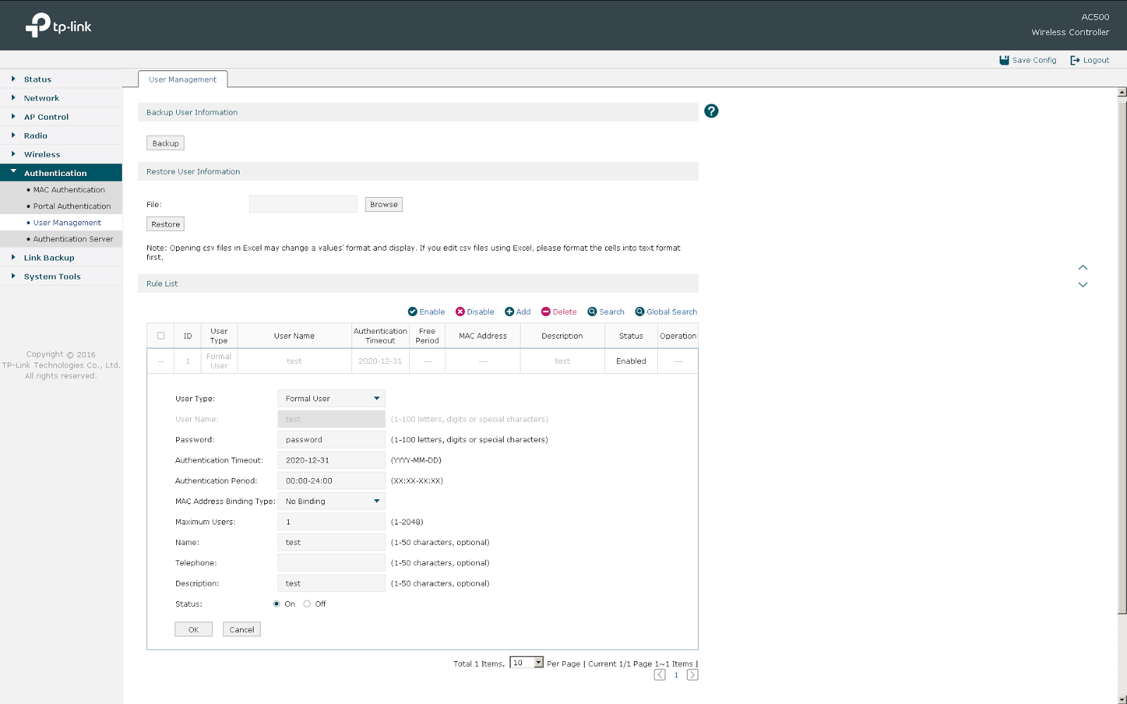
TP-Link AC50 / 500 wireless controllers allow web authentication based on a local list of users stored on the controller itself and using a remote RADIUS server.
It should be noted that in the latest firmware version for the AC500 wireless controller, it was possible to log in via Facebook (Facebook Wi-Fi), as well as SMS-authorization using the twilio service.
Now consider the following models of wireless subscribers in the wired part of the network.
Network traffic distribution models
Depending on the relative position and settings of the wireless controller, access points and wired network segment, several typical patterns of user traffic movement are possible. They must be taken into account when designing a wireless network in order to avoid overload in the wired segment. It is worth noting here that at the moment, TP-Link wireless equipment does not encapsulate user data in the CAPWAP tunnel, that is, access points and controllers perform the so-called local switching, which leads to the need to either keep “stretched” VLANs on the network or use local VLANs with multiple IP subnets.
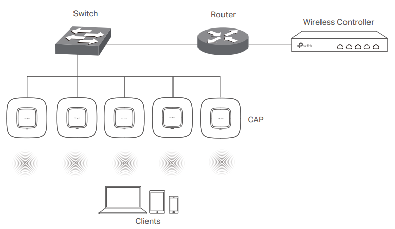
Access Points Connect Directly to a Wireless Controller
This model can usually be found in small wireless networks, where the number of access points is relatively small. Access points can be connected either directly to the ports of the wireless controller, or to auxiliary switches with or without PoE support.
Regardless of whether the controller commutes or routes user traffic, the link between the switch and the controller (Fast Ethernet for AC50 and Gigabit Ethernet for AC500) can be a bottleneck.
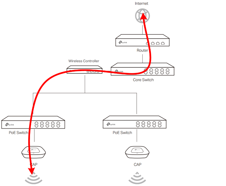
The controller acts as the default gateway for wireless networks
This model does not regulate the mutual arrangement of the wireless controller and access points in the network. The fundamental fact is such a configuration of network equipment and client devices, in which the controller acts as a default gateway for wireless clients. In this case, the link between the switch and the controller will also be overloaded.
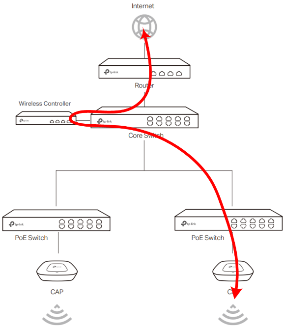
The default gateway functions are assigned to the router or L3 switch
This model is the most optimal in terms of performance, since the wireless controller is completely excluded from the transmission of user traffic. Access points essentially act as bridges by associating a wireless SSID with a VLAN in a wired segment. All further traffic processing is done by wired switches and routers.
Apply this scheme optimally in large distributed networks with a large number of access points and wireless clients. It is also worth noting that TP-Link wireless controllers support the N + N redundancy function, working in a fault-tolerant pair.
We decided to slightly dilute the description of the controller's capabilities and how to connect it with a little testing in order to “live” show the operation of the device and access points.
The AC500 Wireless Controller is capable of routing traffic for two Gigabit Ethernet ports at medium speed in Full Duplex mode, making full use of the resources of both processor cores. Thus, with the AC500 as a router, users will be able to receive a total of 2 Gbit / s in large packets.
It should be noted that traffic switching is performed by the AC500 controller practically without using a central processor, which allows you to use all five Gigabit Ethernet ports in L2 mode at medium speed, while leaving the CPU resources free for other tasks.
The CAP1750 access point provides users with a maximum theoretical speed of 450 Mbps in the 2.4 GHz band and 1.3 Gbit / s in the 5 GHz band. In practice, when using the CAP1750 model in the 2.4 GHz band, the total speed of simultaneous transmission of user data in both directions is about 260 Mbps. For the 5 GHz band, this value is 620 Mbps. We decided to present the results in a diagram.
The main characteristics of the test bench used for measurements are listed below. All measurements were made for 15 simultaneous TCP connections. The access point and the wireless client were located in close proximity to each other.
| Component | PC | A laptop |
| Motherboard | ASUS Maximus VIII Extreme | ASUS M60J |
| CPU | Intel Core i7 7700K 4 GHz | Intel Core i7 720QM 1.6 GHz |
| RAM | DDR4-2133 Samsung 64 GB | DDR3 PC3-10700 SEC 16 GB |
| LAN card | ASUS PCE-AC88 | Atheros AR8131 |
| operating system | Windows 7 x64 SP1 | Windows 7 x64 SP1 |
| Measuring software | JPerf 2.0.2 | JPerf 2.0.2 |
Thus, in practice, one CAP1750 access point will be able to transmit about 900 Mbps of traffic to the wired network when connecting wireless clients to both frequency ranges. The indicated speeds must be taken into account when building or updating a wireless network, possibly reducing over-subscription in the wired segment.
Firmware update
The wireless controller and access points are ready to work right out of the box, but we always strongly recommend updating the software preinstalled on the devices. The new firmware will not only correct detected inaccuracies in the code, but also add new features. For example, one of the most interesting innovations for our equipment will be support for cloud management, which allows centralized management of several wireless controllers at once. This option will be in demand in the case of very large or distributed objects. We are also implementing IPv6 protocol support, which will allow us to use our wireless equipment in next-generation IP networks. For network administrators, we have added support for SNMP, with the help of which there is the possibility of centralized device management and collection of statistics on the use of the controller and access points. As well as command line support.
Software updates for any of our wireless controllers are done via the web interface. The whole process takes about five minutes and does not require any special knowledge from the user.
The way to replace firmware on access points depends on the mode in which they work: FIT or FAT. In FAT mode, the access point acts as a standalone device, so the firmware version is changed using the web interface of a specific device.
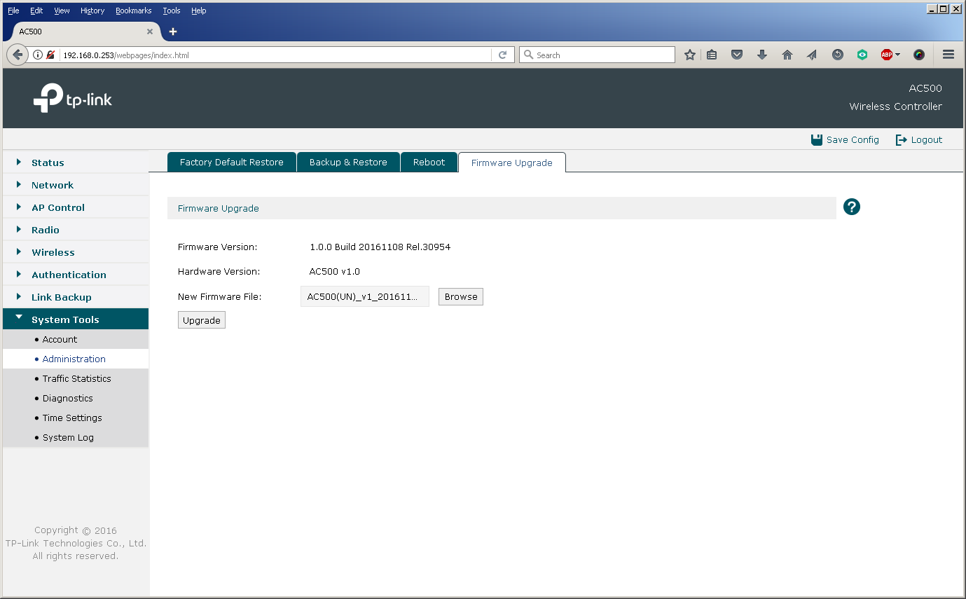
When building a wireless network on a large or complex facility, many wireless access points are needed to provide a continuous coverage zone. In this case, they are controlled (in FIT mode) using a wireless controller. To update their firmware it is also necessary to use a controller. The centralized change of firmware versions of access points is carried out using the controller’s web interface, where it is necessary to download a file containing the new firmware version, as well as indicate the start time of the update. You can also see a list of access points that it will affect.
The possibility of a centralized update is especially useful for the AC500 wireless controller, since this model supports up to 500 access points at the same time, which makes manual replacement of firmware on an escorted object almost impossible.
Since our range of equipment is constantly updated, after the release of a new model (for example, CAP1200), it is necessary to update the database of supported devices on the controller in order to expand the list of managed equipment.
In the dry residue
As we showed above, the installation and configuration of TP-Link equipment is extremely simple, and a large number of modifiable parameters allows you to flexibly configure the network in accordance with all the wishes of the customer. Below we will list those key features of our products that we consider the most popular and relevant when building large-scale networks:
- automatic discovery and centralized management of access points;
- the ability to locally and remotely host access points;
- load balancing;
- support for local switching of user traffic by access points;
- Unified customization
- the possibility of hot standby wireless controller;
- PoE support
- lack of moving parts for controllers and access points;
- support for multiple SSIDs;
- various methods of user authentication;
- flexibility and scalability of the solution;
- 3 year warranty and technical support in Russian.