Creating a 3D printer shader effect
- Transfer
In this tutorial, we will recreate the 3D printer effect used in games such as Astroneer and Planetary Annihilation . This is an interesting effect showing the process of creating an object. Despite the external simplicity, it has many far from trivial difficulties.
To recreate this effect, let's start with something simpler. For example, from a shader that colors an object differently depending on its position. To do this, you need to access the position of the rendered pixels in the world. This can be done by adding a field
Then you can use the Y coordinate of the world position in the surface function to change the color of the object. This can be achieved by changing the properties
The result is a first approximation to the effect of Astroneer. The main problem is that a shaded display is still in progress for the color part.
In the previous tutorial on PBR and Lighting Models, we explored a way to create our own lighting models for surface shaders. An unlit shader always creates the same color, regardless of external lighting and viewing angle. You can implement it as follows:
His only task is to return a single solid color. As we can see, it refers to
The parameter
Unfortunately, the lighting function does not have access to the position of the object. The simplest way to provide this information is to use a Boolean variable (
The last problem that we are faced with is quite complex. As I explained in the previous section, we can use
In the traditional standard surface shader, the directive
By Unity naming standards, it’s easy to see what function is used should be called
We want to create our own lighting function called
To compile this code, Unity 5 needs to define another function:
It is used to calculate the degree to which lighting affects global lighting, but for the purposes of our tutorial it is optional.
The result will be exactly what we need:
In this first part, we learned how to use two different lighting models in one shader. This allowed us to render one half of the model using PBR and leave the other unlit. In the second part, we will complete this tutorial and show how to animate and improve the effect.
The easiest way to add to our shader is the effect of stopping the rendering of the upper part of the geometry. To cancel the rendering of an arbitrary pixel in the shader, you can use the keyword
It is important to remember that this can leave “holes” in our geometry. It is necessary to disable the clipping of the faces so that the reverse side of the object is completely drawn.
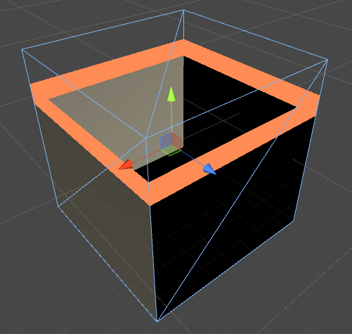
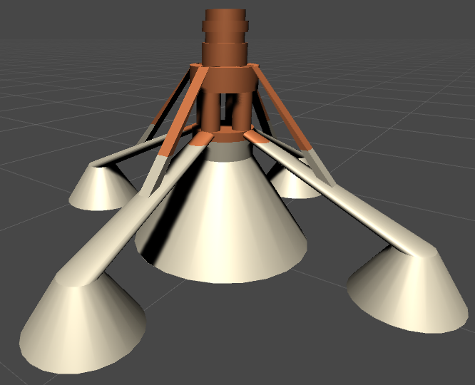
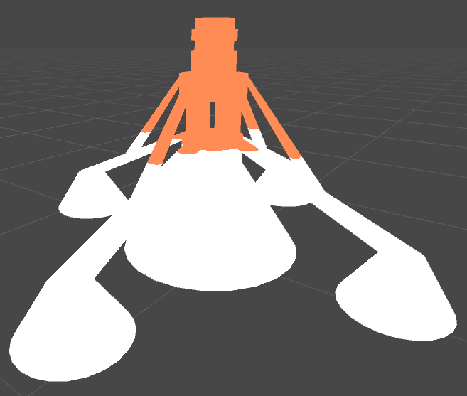
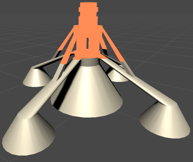
Now we are most uncomfortable with the fact that the object looks hollow. This is not just a feeling: in fact, all 3D models are hollow. However, we need to create the illusion that the object is actually solid. This can easily be achieved by painting the object from the inside with the same unlit shader. The object is still hollow, but perceived to be full.
To achieve this, we simply color the triangles directed towards the camera with the back side. If you are unfamiliar with vector algebra, then this may seem quite complicated. In fact, this can be quite easily achieved using the scalar product. The scalar product of two vectors shows how “directed” they are. And this is directly related to the angle between them. When the scalar product of two vectors is negative, then the angle between them is greater than 90 degrees. We can check our initial condition by taking the scalar product between the direction of the camera's gaze (
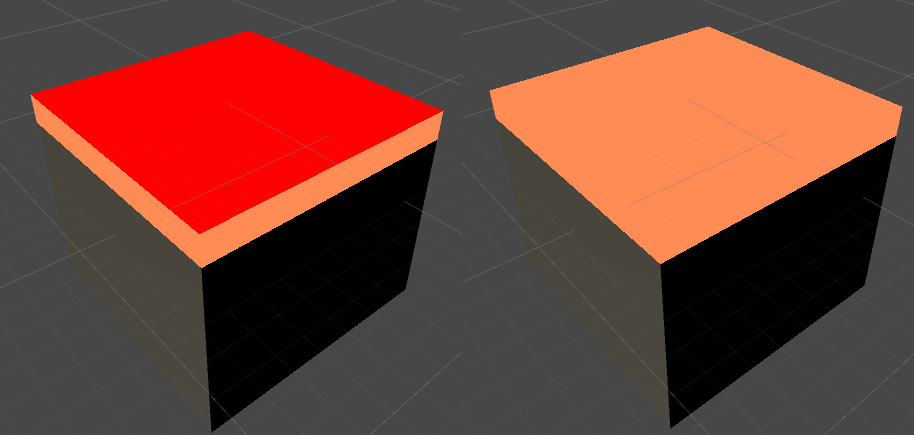
The result is shown in the images below. On the left, the “wrong geometry” is rendered in red. If you use the color of the top of the object, then the object no longer looks hollow.
If you played Planetary Annihilation, then you know that the shader of the 3D printer uses the effect of a small waviness. We can also implement it by adding a bit of noise to the position of the rendered pixels in the world. This can be achieved either by noise texture, or by using a continuous periodic function. In the code below, I use a sine wave with arbitrary parameters.
These parameters can be adjusted manually to obtain a beautiful wavy effect.
The last part of the effect is the animation. It can be obtained by simply adding a parameter to the material
I note at the end that the model used in this image looks hollow for several seconds, because the lower part of the accelerators is open. That is, the object is actually hollow.
[You can download the Unity package (code, shader, and 3D models) by supporting the author of the original article with ten dollars on Patreon.]
Introduction: First Attempt
To recreate this effect, let's start with something simpler. For example, from a shader that colors an object differently depending on its position. To do this, you need to access the position of the rendered pixels in the world. This can be done by adding a field
worldPosto the InputUnity 5 surface shader structure .struct Input {
float2 uv_MainTex;
float3 worldPos;
};Then you can use the Y coordinate of the world position in the surface function to change the color of the object. This can be achieved by changing the properties
Albedoin the structure SurfaceOutputStandard.float _ConstructY;
fixed4 _ConstructColor;
voidsurf (Input IN, inout SurfaceOutputStandard o) {
if (IN.worldPos.y < _ConstructY)
{
fixed4 c = tex2D(_MainTex, IN.uv_MainTex) * _Color;
o.Albedo = c.rgb;
o.Alpha = c.a;
}
else
{
o.Albedo = _ConstructColor.rgb;
o.Alpha = _ConstructColor.a;
}
o.Metallic = _Metallic;
o.Smoothness = _Glossiness;
}The result is a first approximation to the effect of Astroneer. The main problem is that a shaded display is still in progress for the color part.
Unlit Surface Shader
In the previous tutorial on PBR and Lighting Models, we explored a way to create our own lighting models for surface shaders. An unlit shader always creates the same color, regardless of external lighting and viewing angle. You can implement it as follows:
#pragma surface surf Unlit fullforwardshadowsinline half4 LightingUnlit (SurfaceOutput s, half3 lightDir, half atten)
{
	return _ConstructColor;
}
His only task is to return a single solid color. As we can see, it refers to
SurfaceOutputthat used in Unity 4. If we want to create our own lighting model that works with PBR and global lighting, we need to implement a function that receives as input SurfaceOutputStandard. In Unity 5, the following function is used for this:inline half4 LightingUnlit (SurfaceOutputStandard s, half3 lightDir, UnityGI gi)
{
return _ConstructColor;
}The parameter
gihere refers to global illumination, but in our unlit shader it does not perform any tasks. This approach works, but it has a big problem. Unity does not allow the surface shader to selectively change the lighting function. We cannot apply standard Lambert lighting to the lower part of the object and at the same time make the upper part unlit. You can assign a single lighting function to the entire subject. We ourselves must change the way the object is rendered, depending on its position.We pass the parameters of the lighting function
Unfortunately, the lighting function does not have access to the position of the object. The simplest way to provide this information is to use a Boolean variable (
building), which we define in the surface function. This variable can be checked by our new lighting function.int building;
voidsurf (Input IN, inout SurfaceOutputStandard o) {
if (IN.worldPos.y < _ConstructY)
{
fixed4 c = tex2D(_MainTex, IN.uv_MainTex) * _Color;
o.Albedo = c.rgb;
o.Alpha = c.a;
building = 0;
}
else
{
o.Albedo = _ConstructColor.rgb;
o.Alpha = _ConstructColor.a;
building = 1;
}
o.Metallic = _Metallic;
o.Smoothness = _Glossiness;
}Extending the standard lighting function
The last problem that we are faced with is quite complex. As I explained in the previous section, we can use
buildingto change the way lighting is calculated. The part of the object that is currently under construction will be unlit, and the remaining part will have correctly calculated lighting. If we want our material to use PBR, we cannot rewrite all the code for photorealistic coverage. The only reasonable solution is to call the standard lighting function that is already implemented in Unity. In the traditional standard surface shader, the directive
#pragmadefining the use of the PBR lighting function is as follows:#pragma surface surf Standard fullforwardshadowsBy Unity naming standards, it’s easy to see what function is used should be called
LightingStandard. This function is located in a file UnityPBSLighting.cgincthat can be connected if necessary. We want to create our own lighting function called
LightingCustom. Under normal circumstances, it simply calls the standard PBR function from Unity called LightingStandard. However, if necessary, it uses the previously defined LightingUnlit.inline half4 LightingCustom(SurfaceOutputStandard s, half3 lightDir, UnityGI gi)
{
if (!building)
return LightingStandard(s, lightDir, gi); // Unity5 PBRreturn _ConstructColor; // Unlit
}To compile this code, Unity 5 needs to define another function:
inline voidLightingCustom_GI(SurfaceOutputStandard s, UnityGIInput data, inout UnityGI gi)
{
	LightingStandard_GI(s, data, gi);
}
It is used to calculate the degree to which lighting affects global lighting, but for the purposes of our tutorial it is optional.
The result will be exactly what we need:
In this first part, we learned how to use two different lighting models in one shader. This allowed us to render one half of the model using PBR and leave the other unlit. In the second part, we will complete this tutorial and show how to animate and improve the effect.
Cut off the geometry
The easiest way to add to our shader is the effect of stopping the rendering of the upper part of the geometry. To cancel the rendering of an arbitrary pixel in the shader, you can use the keyword
discard. With it, you can draw only the border around the top of the model:voidsurf (Input IN, inout SurfaceOutputStandard o)
{
if (IN.worldPos.y > _ConstructY + _ConstructGap)
discard;
...
}It is important to remember that this can leave “holes” in our geometry. It is necessary to disable the clipping of the faces so that the reverse side of the object is completely drawn.
Cull OffNow we are most uncomfortable with the fact that the object looks hollow. This is not just a feeling: in fact, all 3D models are hollow. However, we need to create the illusion that the object is actually solid. This can easily be achieved by painting the object from the inside with the same unlit shader. The object is still hollow, but perceived to be full.
To achieve this, we simply color the triangles directed towards the camera with the back side. If you are unfamiliar with vector algebra, then this may seem quite complicated. In fact, this can be quite easily achieved using the scalar product. The scalar product of two vectors shows how “directed” they are. And this is directly related to the angle between them. When the scalar product of two vectors is negative, then the angle between them is greater than 90 degrees. We can check our initial condition by taking the scalar product between the direction of the camera's gaze (
viewDirin the surface shader) and the normal of the triangle. If it is negative, then the triangle is turned away from the camera. That is, we see its “inside out” and can render it in solid color.struct Input {
float2 uv_MainTex;
float3 worldPos;
float3 viewDir;
};
voidsurf (Input IN, inout SurfaceOutputStandard o)
{
viewDir = IN.viewDir;
...
}
inline half4 LightingCustom(SurfaceOutputStandard s, half3 lightDir, UnityGI gi)
{
if (building)
return _ConstructColor;
if (dot(s.Normal, viewDir) < 0)
return _ConstructColor;
return LightingStandard(s, lightDir, gi);
}The result is shown in the images below. On the left, the “wrong geometry” is rendered in red. If you use the color of the top of the object, then the object no longer looks hollow.
Wavy effect
If you played Planetary Annihilation, then you know that the shader of the 3D printer uses the effect of a small waviness. We can also implement it by adding a bit of noise to the position of the rendered pixels in the world. This can be achieved either by noise texture, or by using a continuous periodic function. In the code below, I use a sine wave with arbitrary parameters.
voidsurf (Input IN, inout SurfaceOutputStandard o)
{
	float s = +sin((IN.worldPos.x * IN.worldPos.z) * 60 + _Time[3] + o.Normal) / 120;
	if (IN.worldPos.y > _ConstructY + s + _ConstructGap)
		discard;
	...
}
These parameters can be adjusted manually to obtain a beautiful wavy effect.
Animation
The last part of the effect is the animation. It can be obtained by simply adding a parameter to the material
_ConstructY. The shader will take care of the rest. You can control the speed of the effect either through the code, or using an animation curve. With the first option, you can fully control its speed.publicclassBuildingTimer : MonoBehaviour
{
public Material material;
publicfloat minY = 0;
publicfloat maxY = 2;
publicfloat duration = 5;
// Update is called once per framevoidUpdate () {
float y = Mathf.Lerp(minY, maxY, Time.time / duration);
material.SetFloat("_ConstructY", y);
}
}I note at the end that the model used in this image looks hollow for several seconds, because the lower part of the accelerators is open. That is, the object is actually hollow.
[You can download the Unity package (code, shader, and 3D models) by supporting the author of the original article with ten dollars on Patreon.]