Drawing thick lines in WebGL
Ready examples
The examples are based on the OpenGlobus engine, which in this case is used as a wrapper over pure Javascript WebGL.
(sorry, the examples do not work yet)
- Example for the 2D case
- Example for the 3D case (use the keys W, S, A, D, Q, E and the cursor to move)
Introduction
In the process of working on the cartographic library, I needed a tool that allowed me to draw lines of different thicknesses. Of course, WebGL has a line drawing mechanism, but unfortunately you cannot set the line thickness. Therefore, you have to draw lines with polygons, it is better to say with triangles. On the Internet you can find some excellent articles on how to “triangulate” the line, what difficulties arise in this case and how to solve them. Unfortunately, I did not find an article from which I could copy the code and use in my shader.
After many hours spent with a pencil and paper on drawing an algorithm, and then numerous hours of debugging a completely uncomplicated glsl shader, I finally came to a result that could be achieved much faster. I hope the approach of rendering polygonal lines in WebGL described below will save your life time, which would otherwise be spent on this task!
Line drawing in two-dimensional space
In my engine for line shaders in two-dimensional and three-dimensional spaces, almost the same code is used. The only difference is that for the three-dimensional case, the projection of the three-dimensional coordinates of the line onto the screen is added, then the same algorithm.
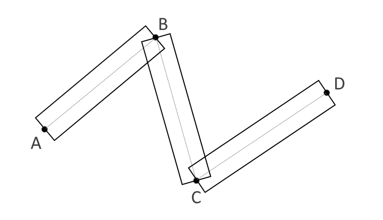
There is a common practice for giving thickness to lines - to represent each line segment as a rectangle. The simplest representation of a thick line is as follows (Fig. 1) :
(Fig. 1)
To get rid of visible segmentation at nodal points, it is necessary to combine adjacent points of adjacent segments in order to preserve the thickness in both sections of adjacent segments. To do this, find the intersection of the one-sided faces of the line, above and below (Fig. 2) :
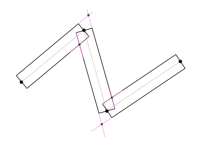
(Fig. 2)
However, the angle between adjacent segments can be so sharp that the intersection point can go far from the connection point of these lines (Fig. 3) .
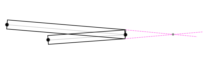
(Fig. 3)
In this case, this angle needs to be processed somehow (Fig. 4) :
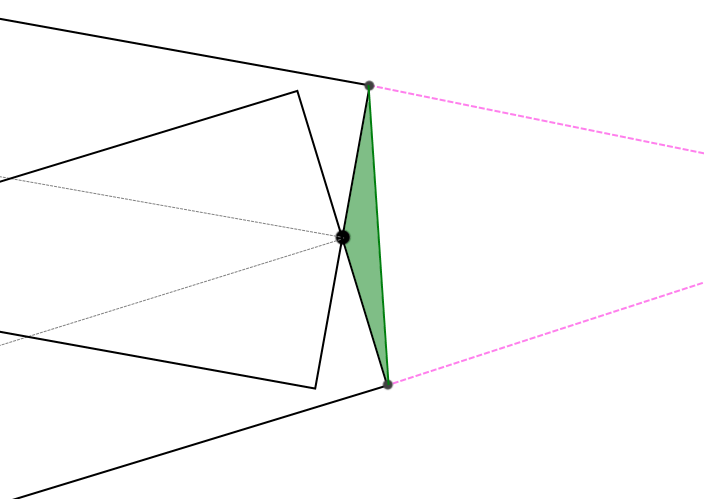
(Fig. 4)
I decided to fill in such areas with corresponding triangles. The GL_LINE_STRING sequence came to my aid, which, if it is in the correct order, should, in the case of an angle that is too sharp (the threshold value is checked in the vertex shader), create the effect of a neatly cropped corner (Fig. 5) , or combine adjacent coordinates of neighboring segments according to the rule of intersecting one-sided faces (Fig. . 2) as before.
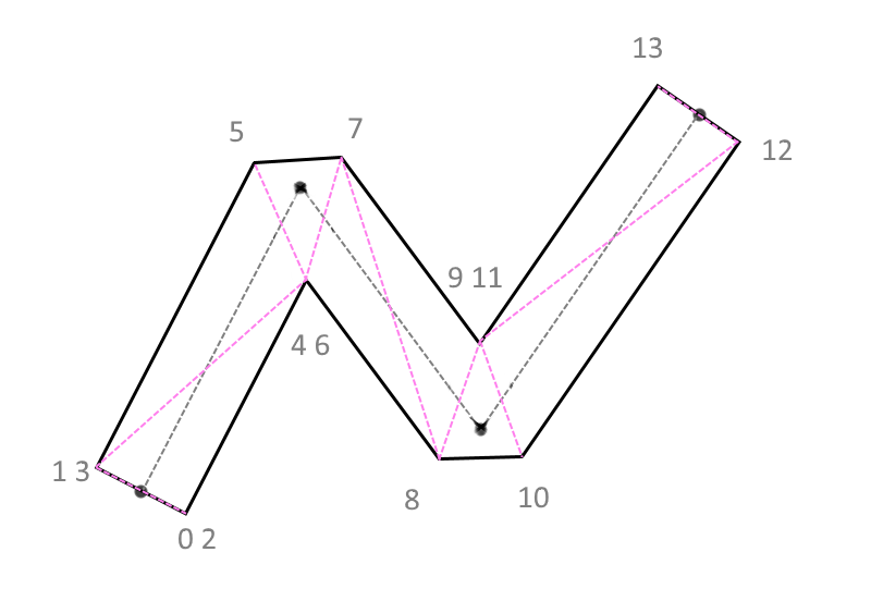
(Fig. 5)
The numbers near the vertices are the indices of the vertices along which the polygons are drawn in the graphics pipeline. If the angle is obtuse, in this case the triangle for cropping will merge into an infinitely thin line and become invisible (Fig. 6) .
 (Fig. 6) To
ourselves, we represent the sequence in this way (Fig. 7) :

(Fig. 7)
That’s the whole secret. Now let's see how this is rendered. It is necessary to create a vertex buffer, an index buffer, and an order buffer that shows in which direction from the current vertex of the segment to thicken, and also which part of the segment is currently being processed by the vertex shader, initial or final. In order to find the intersection of the faces, in addition to the coordinates of the current point, we also need to know the previous and next coordinates from it (Fig. 8) .
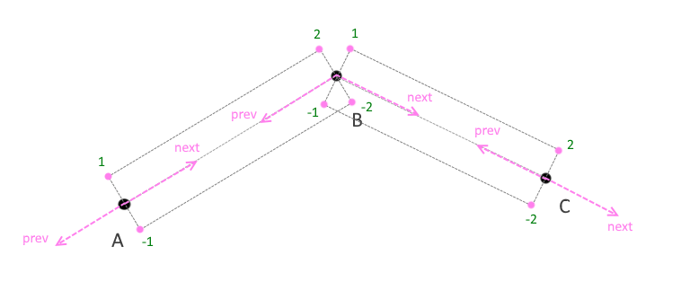
(Fig. 8)
So, for each coordinate in the shader, we must actually have the coordinate itself, the previous and next coordinates, the order of the point i.e. whether the point is the beginning or the end of the segment (I mean -1, 1 is the beginning and -2, 2 is the end of the segment), how it should be located: above or below the current coordinate, as well as thickness and color.
Because WebGL allows you to use one buffer for different attributes, then if the element of this buffer is a coordinate, when vertexAttribPointer is called , each attribute is assigned in bytes the size of the buffer element, and the offset relative to the current attribute element. This can be clearly seen if we depict the sequence on paper (Fig. 9) :
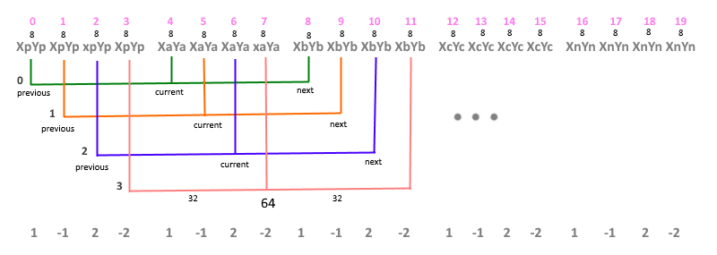
(Fig. 9) The
top line is the indices in the vertex array; 8 - element size ( coordinate type vec2) i.e. 2x4 bytes; Xi, Yi - coordinate values at points A, B, C ;Xp = Xa - Xb, Yp = Ya - Yb, Xn = Xc - Xb, Yn = Xc - Xb i.e. peaks indicating direction at border points. Colored arcs show the coordinate bundles (previous, current, and next) for each index in the vertex shader, where current is the current coordinate of the link, previous is the previous coordinate of the link, and next is the next coordinate of the link. The value 32 bytes is the offset in the buffer in order to identify the current (current) relative to the previous (previous) coordinate value, 64 bytes is the offset in the buffer to identify the next (next)values. Because Since the index of the next coordinate begins with the previous (previous) value, then for it the offset in the array is zero. The last line shows the order of each coordinate in the segment, 1 and -1 - this is the beginning of the segment, 2 and -2 - respectively, the end of the segment.
In code, it looks like this:
var vb = this._verticesBuffer;
gl.bindBuffer(gl.ARRAY_BUFFER, vb);
gl.vertexAttribPointer(sha.prev._pName, vb.itemSize, gl.FLOAT, false, 8, 0);
gl.vertexAttribPointer(sha.current._pName, vb.itemSize, gl.FLOAT, false, 8, 32);
gl.vertexAttribPointer(sha.next._pName, vb.itemSize, gl.FLOAT, false, 8, 64);
gl.bindBuffer(gl.ARRAY_BUFFER, this._ordersBuffer);
gl.vertexAttribPointer(sha.order._pName, this._ordersBuffer.itemSize, gl.FLOAT, false, 4, 0);
This is the function that creates arrays of vertices and orders, where pathArr is an array of coordinate arrays along which the arrays are filled to initialize buffers outVertices is an array of coordinates, outOrders is an array of orders and outIndexes is an array of indices:
Polyline2d.createLineData = function (pathArr, outVertices, outOrders, outIndexes) {
    var index = 0;
    outIndexes.push(0, 0);
    for ( var j = 0; j < pathArr.length; j++ ) {
        path = pathArr[j];
        var startIndex = index;
        var last = [path[0][0] + path[0][0] - path[1][0], path[0][1] + path[0][1] - path[1][1]];
        outVertices.push(last[0], last[1], last[0], last[1], last[0], last[1], last[0], last[1]);
        outOrders.push(1, -1, 2, -2);
        //На каждую вершину приходится по 4 элемента
        for ( var i = 0; i < path.length; i++ ) {
            var cur = path[i];
            outVertices.push(cur[0], cur[1], cur[0], cur[1], cur[0], cur[1], cur[0], cur[1]);
            outOrders.push(1, -1, 2, -2);
            outIndexes.push(index++, index++, index++, index++);
        }
        var first = [path[path.length - 1][0] + path[path.length - 1][0] - path[path.length - 2][0],  path[path.length - 1][1] + path[path.length - 1][1] - path[path.length - 2][1]];
        outVertices.push(first[0], first[1], first[0], first[1], first[0], first[1], first[0], first[1]);
        outOrders.push(1, -1, 2, -2);
        outIndexes.push(index - 1, index - 1, index - 1, index - 1);
        if ( j < pathArr.length - 1 ) {
            index += 8;
            outIndexes.push(index, index);
        }
    }
};
Example:
var path = [[[-100, -50], [1, 2], [200, 15]]];
var vertices = [],
     orders = [],
     indexes = [];
Polyline2d.createLineData(path, vertices, orders, indexes);
We get:
vertices: [-201, -102, -201, -102, -201, -102, -201, -102, -100, -50, -100, -50, -100, -50, -100, -50, 1, 2, 1, 2, 1, 2, 1, 2, 200, 15, 200, 15, 200, 15, 200, 15, 399, 28, 399, 28, 399, 28, 399, 28 ]
orders: [1, -1, 2, -2, 1, -1, 2, -2, 1, -1, 2, -2, 1, -1, 2, -2, 1, -1, 2 , -2]
indexes: [0, 0, 0, 1, 2, 3, 4, 5, 6, 7, 8, 9, 10, 11, 11, 11, 11, 11]
Vertex Shader:
attribute vec2 prev; //предыдущая координата
attribute vec2 current; //текущая координата
attribute vec2 next; //следующая координата
attribute float order; //порядок
uniform float thickness; //толщина
uniform vec2 viewport; //размеры экрана
//Функция проецирование на экран
vec2 proj(vec2 coordinates){
    return coordinates / viewport;
}
void main() {
    vec2 _next = next;
    vec2 _prev = prev;
    //Блок проверок для случаев, когда координаты точек равны
    if( prev == current ) {
        if( next == current ){
            _next = current + vec2(1.0, 0.0);
            _prev = current - next;
        } else {
            _prev = current + normalize(current - next);
        }
    }
    if( next == current ) {
        _next = current + normalize(current - _prev);
    }
    vec2 sNext = _next,
            sCurrent = current,
            sPrev = _prev;
    //Направляющие от текущей точки, до следующей и предыдущей координаты
    vec2 dirNext = normalize(sNext - sCurrent);
    vec2 dirPrev = normalize(sPrev - sCurrent);
    float dotNP = dot(dirNext, dirPrev);
    //Нормали относительно направляющих
    vec2 normalNext = normalize(vec2(-dirNext.y, dirNext.x));
    vec2 normalPrev = normalize(vec2(dirPrev.y, -dirPrev.x));
    float d = thickness * 0.5 * sign(order);
    vec2 m; //m - точка сопряжения, от которой зависит будет угол обрезанным или нет
    if( dotNP >= 0.99991 ) {
        m = sCurrent - normalPrev * d;
    } else {
        vec2 dir = normalPrev + normalNext;
        // Таким образом ищется пересечение односторонних граней линии (рис. 2)
        m = sCurrent + dir * d / (dirNext.x * dir.y - dirNext.y * dir.x);
        //Проверка на пороговое значение остроты угла
        if( dotNP > 0.5 && dot(dirNext + dirPrev, m - sCurrent) < 0.0 ) {
            float occw = order * sign(dirNext.x * dirPrev.y - dirNext.y * dirPrev.x);
            //Блок решения для правильного построения цепочки LINE_STRING
            if( occw == -1.0 ) {
                m = sCurrent + normalPrev * d;
            } else if ( occw == 1.0 ) {
                m = sCurrent + normalNext * d;
            } else if ( occw == -2.0 ) {
                m = sCurrent + normalNext * d;
            } else if ( occw == 2.0 ) {
                m = sCurrent + normalPrev * d;
            }
        //Проверка "внутренней" точки пересечения, чтобы она не убегала за границы сопряженных сегментов
        } else if ( distance(sCurrent, m) > min(distance(sCurrent, sNext), distance(sCurrent, sPrev)) ) {
            m = sCurrent + normalNext * d;
        }
    }
    m = proj(m);
    gl_Position = vec4(m.x, m.y, 0.0, 1.0);
}
A few words in conclusion
This approach is implemented for drawing tracks, orbits , vector data .
In conclusion, I want to add some ideas on what can be done with the algorithm to improve the quality of the lines. For example, you can pass the color in the colors attribute for each vertex, then the line will become multi-colored. You can also transmit width to each vertex, then the line will change in width from point to point, and if you calculate the width at a point (in the vertex shader) relative to the distance from the observation point (for the three-dimensional case) , you can achieve the effect when part of the line is located closer to the observation point visually larger than the part of the line that is at a distance. Still it is possible to realize the smoothing (antialiasing)by adding two passes for each of the edges of the thick line, in which thin lines are drawn (a frame around the edges) with little transparency relative to the central part.