Work with the KOMPAS-3D API → Lesson 1 → Basics
- Tutorial
Designers and engineers are accustomed to working in KOMPAS, manually building drawings, 3D-models and assemblies. However, the COMPASS system provides a rich set of functions to automate their work. If you wish, the whole process of building a complex drawing, 3D-model or assembly can be reduced to clicking on one button. The truth for this will have to work for us programmers.
In the framework of one article, it is impossible to describe all the COMPASS automation capabilities. Not even a book is enough for this. Fortunately for us, the KOMPAS package includes documentation, header files for various programming languages, and a number of examples.

Narrated by Sergey Alexandrovich Norseev - software engineer, VNII Signal JSC, Kovrov. Author of the book "Application Development for COMPAS in Delphi"
The documentation is in the form of a single CHM file. It is located in the SDK directory of the COMPASS catalog. On my home computer, for example, the full path to it looks like this: "C: \ Program Files \ ASCON \ KOMPAS-3D v17 \ SDK \ SDK.chm . " The image below shows the contents of this file.
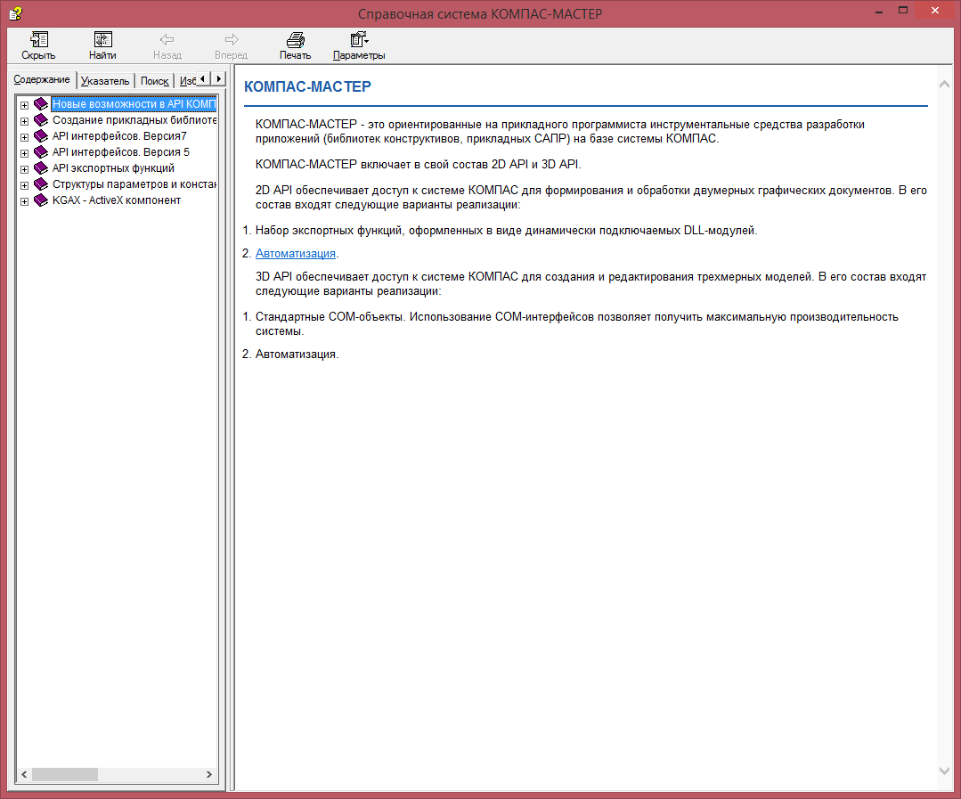
This file provides a complete description of all interfaces, their properties and methods. In this article we will give only a brief overview of interaction with KOMPAS through COM interfaces of version 5. In
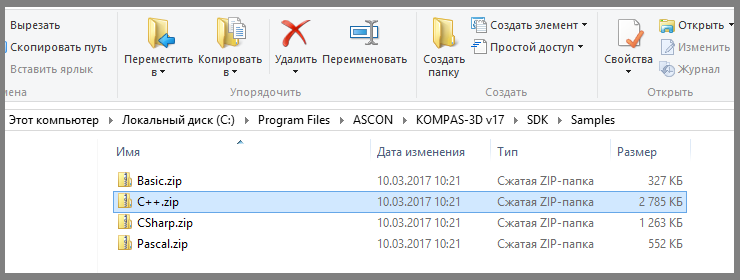
addition to the documentation, KOMPAS comes with a large number of programming examples for this system in different programming languages. They are located in the same directory as the documentation. By opening the SDK directory, you will see several archives whose names correspond to programming languages: “Basic” , “C #” , “C ++” and “Pascal” . They are examples. We will use the C ++ language, unzip the corresponding archive to any place convenient for you. The environment used is C ++ Builder.
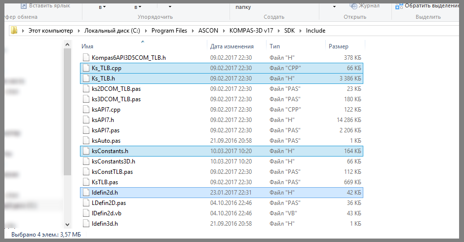
Before we begin, we need header files. They are located in the "SDK \ Include \" directory . We need the following files.
Ks_TLB.h and Ks_TLB.cpp . They contain declarations of all major interfaces. These are the core files.
“KsConstants.h” and “ldefin2D.h” . These are optional files that specify various constants.
After these files are connected to our project, we can start working.
The KOMPAS system itself in the “Interface Interfaces API 5” is described by the KompasObject interface . The corresponding COM object is specified by the string "KOMPAS.Application.5" . The following is an example of connecting to COMPASS.
The “KompasObjectPtr” data type sets a pointer to the KompasObject interface .
As a result of this program, the main COMPASS program window will appear on the screen. It will not open a single document.
To close the COMPASS program, use the Quit () method of the KompasObject interface . One of the most important methods of the KompasObject interface is the GetParamStruct method . It returns a pointer to the parameter interface of an object of one type or another. The requested object type is passed to the method as the value of a single parameter. In total, according to the KOMPAS documentation, through this method you can get 129 parameter interfaces for objects of various types.
Creating a drawing and a fragment occurs in two stages. At the first stage, the parameters of the created document are prepared. On the second, the document itself is created. This two-stage approach is used to create almost all objects in the COMPASS system.
Document parameters are described by the ksDocumentParam interface . To get a pointer to it using the method GetParamStruct interface KompasObject with parameter ko_DocumentParam . The main property of this interface is the type property , which indicates the type of the document described by this interface.
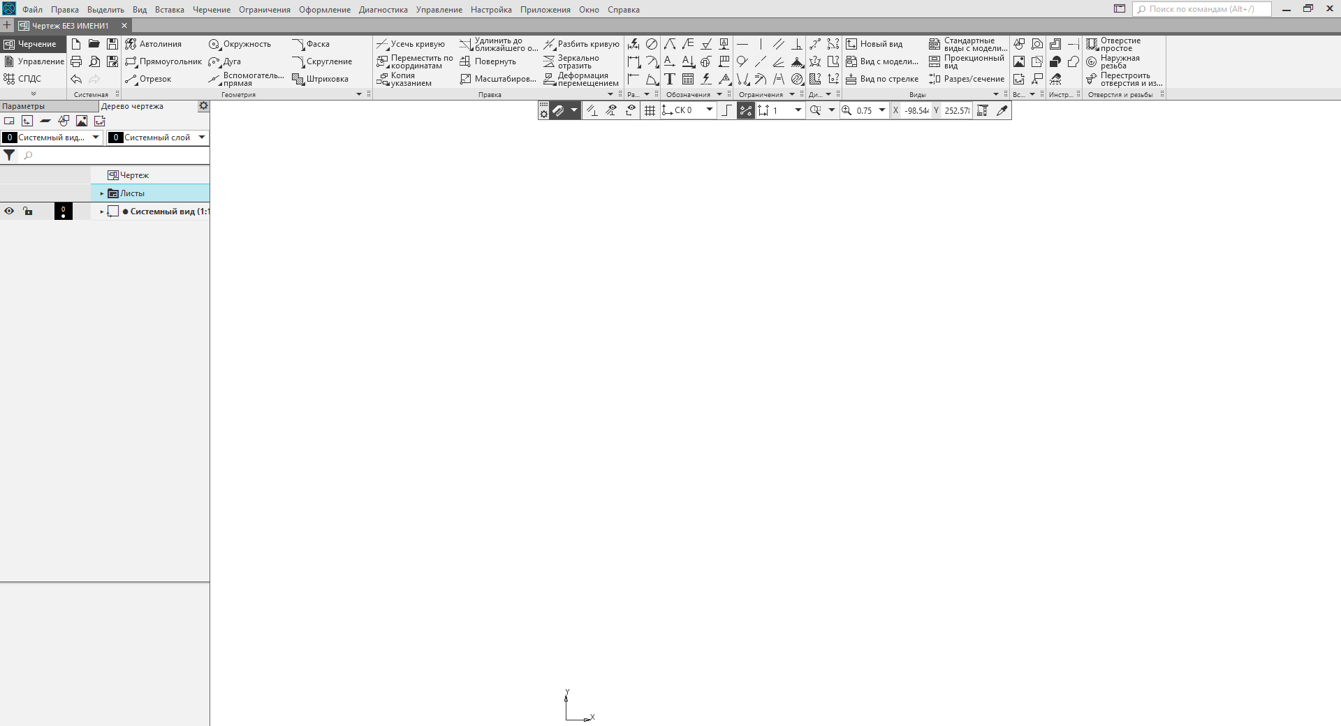
The drawing and fragment are described by the ksDocument2D interface. You can get a pointer to it using the Document2D method of the KompasObject interface . The following is an example of a program that creates a new drawing.
As a result of this program, the main COMPASS program window with a new drawing will appear on the screen. This drawing will have neither a frame nor a main inscription, since we did not configure them.
To create a fragment , specify the value lt_DocFragment in the type field of the ksDocumentParam interface . In all other respects, the process of creating a new fragment is similar to the process of creating a drawing.
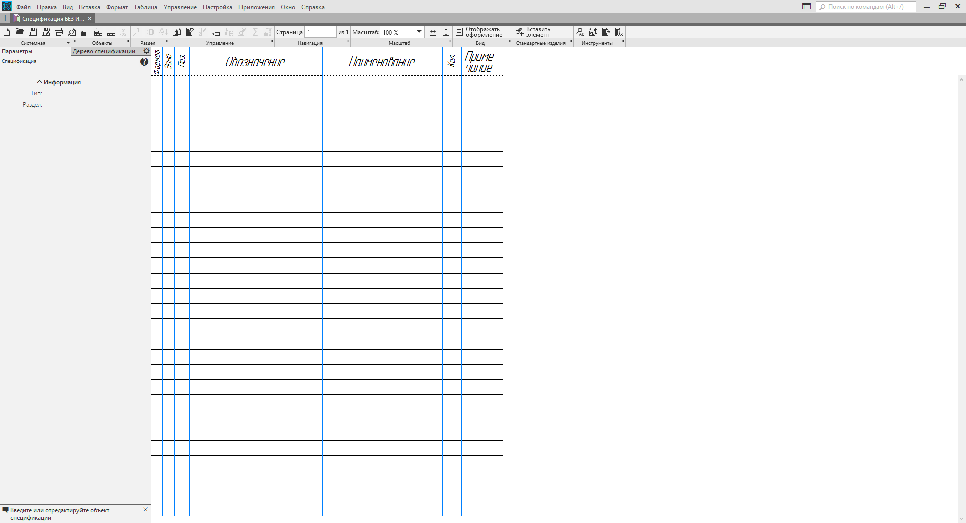
Creating a specification is like creating a drawing and a fragment. The ksDocumentParam interface is also used here . But there are a number of differences. First, the specification is described by the ksSpcDocument interface . A pointer to the interface method returns SpcDocument () interface KompasObject . Secondly, if you create a specification, you must specify the full path to the style library. If it is not specified, then the system will not create a specification. A style library is a graphic.lyt file . It is located in the Sys \ KOMPAS directory . The following is an example of a program that creates a specification.
I will make three important points to the above example.
As a result of the work of this program, the COMPASS window will appear on the screen with the specification created in it.
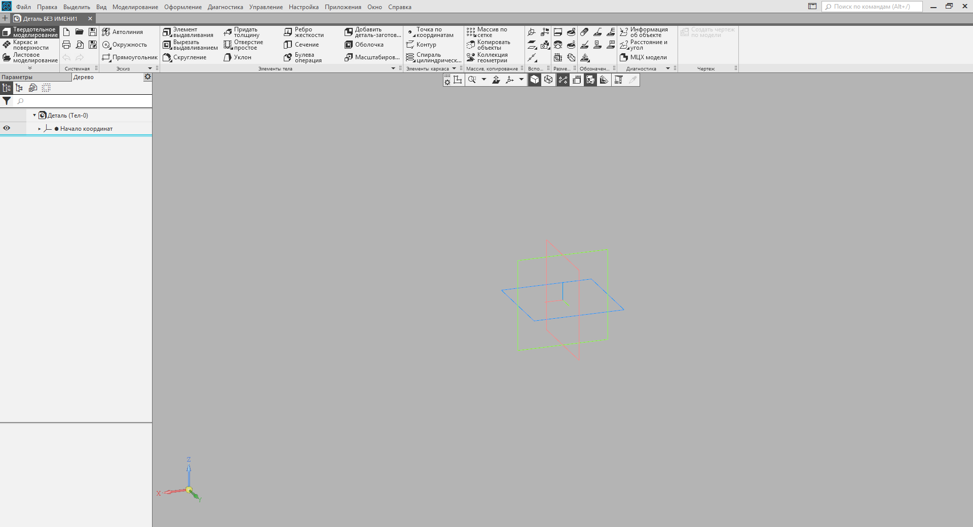
The part and assembly in KOMPAS are described by the ksDocument3D interface . More specifically, this interface describes a file containing a part or assembly. To get a pointer to the ksDocument3D interface , use the Document3D () method of the KompasObject interface . The following is an example of creating a part.
The Create method of the ksDocument3D interface has two input parameters. They are listed below.
This shows that to create an assembly in the above example, you just need to change the value of the second parameter in the Create method .
Conclusion
In this article, I showed a small part of the tip of the iceberg called "interaction with the COMPAS system through COM interfaces." I just showed how to connect to COMPASS and how to create documents of all basic types (drawing, fragment, specification, part and assembly). These documents are created without content. How to fill them will be described in the following articles. Stay tuned for blog news.
Second part.
 Sergey Norseev, author of the book "Application Development for COMPAS in Delphi."
In the framework of one article, it is impossible to describe all the COMPASS automation capabilities. Not even a book is enough for this. Fortunately for us, the KOMPAS package includes documentation, header files for various programming languages, and a number of examples.
Narrated by Sergey Alexandrovich Norseev - software engineer, VNII Signal JSC, Kovrov. Author of the book "Application Development for COMPAS in Delphi"
Documentation and Examples
The documentation is in the form of a single CHM file. It is located in the SDK directory of the COMPASS catalog. On my home computer, for example, the full path to it looks like this: "C: \ Program Files \ ASCON \ KOMPAS-3D v17 \ SDK \ SDK.chm . " The image below shows the contents of this file.
This file provides a complete description of all interfaces, their properties and methods. In this article we will give only a brief overview of interaction with KOMPAS through COM interfaces of version 5. In
addition to the documentation, KOMPAS comes with a large number of programming examples for this system in different programming languages. They are located in the same directory as the documentation. By opening the SDK directory, you will see several archives whose names correspond to programming languages: “Basic” , “C #” , “C ++” and “Pascal” . They are examples. We will use the C ++ language, unzip the corresponding archive to any place convenient for you. The environment used is C ++ Builder.
Header files
Before we begin, we need header files. They are located in the "SDK \ Include \" directory . We need the following files.
Ks_TLB.h and Ks_TLB.cpp . They contain declarations of all major interfaces. These are the core files.
“KsConstants.h” and “ldefin2D.h” . These are optional files that specify various constants.
After these files are connected to our project, we can start working.
Connection to COMPASS
The KOMPAS system itself in the “Interface Interfaces API 5” is described by the KompasObject interface . The corresponding COM object is specified by the string "KOMPAS.Application.5" . The following is an example of connecting to COMPASS.
KompasObjectPtr kompas;
//Запускаем КОМПАС
kompas.CreateInstance(L"KOMPAS.Application.5");
//Делаем его видимым
kompas->Visible = true;
//Отключаемся от него
kompas.Unbind();
The “KompasObjectPtr” data type sets a pointer to the KompasObject interface .
As a result of this program, the main COMPASS program window will appear on the screen. It will not open a single document.
To close the COMPASS program, use the Quit () method of the KompasObject interface . One of the most important methods of the KompasObject interface is the GetParamStruct method . It returns a pointer to the parameter interface of an object of one type or another. The requested object type is passed to the method as the value of a single parameter. In total, according to the KOMPAS documentation, through this method you can get 129 parameter interfaces for objects of various types.
Drawing and fragment
Creating a drawing and a fragment occurs in two stages. At the first stage, the parameters of the created document are prepared. On the second, the document itself is created. This two-stage approach is used to create almost all objects in the COMPASS system.
Document parameters are described by the ksDocumentParam interface . To get a pointer to it using the method GetParamStruct interface KompasObject with parameter ko_DocumentParam . The main property of this interface is the type property , which indicates the type of the document described by this interface.
The drawing and fragment are described by the ksDocument2D interface. You can get a pointer to it using the Document2D method of the KompasObject interface . The following is an example of a program that creates a new drawing.
KompasObjectPtr kompas;
//Запускаем КОМПАС
kompas.CreateInstance(L"KOMPAS.Application.5");
//Подготавливаем параметры документа
DocumentParamPtr DocumentParam;
DocumentParam=(DocumentParamPtr)kompas->GetParamStruct(ko_DocumentParam);
DocumentParam->Init();
DocumentParam->type = lt_DocSheetStandart; //Тип: чертеж
//Создаем чертеж
Document2DPtr Document2D;
Document2D = (Document2DPtr)kompas->Document2D();
Document2D->ksCreateDocument(DocumentParam);
//Делаем КОМПАС видимым
kompas->Visible = true;
kompas.Unbind();
As a result of this program, the main COMPASS program window with a new drawing will appear on the screen. This drawing will have neither a frame nor a main inscription, since we did not configure them.
To create a fragment , specify the value lt_DocFragment in the type field of the ksDocumentParam interface . In all other respects, the process of creating a new fragment is similar to the process of creating a drawing.
Specification
Creating a specification is like creating a drawing and a fragment. The ksDocumentParam interface is also used here . But there are a number of differences. First, the specification is described by the ksSpcDocument interface . A pointer to the interface method returns SpcDocument () interface KompasObject . Secondly, if you create a specification, you must specify the full path to the style library. If it is not specified, then the system will not create a specification. A style library is a graphic.lyt file . It is located in the Sys \ KOMPAS directory . The following is an example of a program that creates a specification.
//Запускаем КОМПАС
KompasObjectPtr kompas;
kompas.CreateInstance(L"KOMPAS.Application.5");
//Подготавливаем параметры документа
DocumentParamPtr DocumentParam;
DocumentParam=(DocumentParamPtr)kompas->GetParamStruct(ko_DocumentParam);
DocumentParam->Init();
DocumentParam->type = lt_DocSpc; //Тип: спецификация
//Формируем полный путь к библиотеке стилей
BSTR str;
str = kompas->ksSystemPath(sptSYSTEM_FILES);
SysReAllocString(&str, SysAllocString(L"\graphic.lyt"));
//Устанавливаем путь к библиотеке стилей
SheetParPtr SheetPar;
SheetPar = (SheetParPtr)DocumentParam->GetLayoutParam();
SheetPar->Init();
SheetPar->layoutName = str;
//Создаем спецификацию
SpcDocumentPtr SpcDocument;
SpcDocument = (SpcDocumentPtr)kompas->SpcDocument();
SpcDocument->ksCreateDocument(DocumentParam);
//Делаем КОМПАС видимым
kompas->Visible = true;
kompas.Unbind();
I will make three important points to the above example.
- To get the path to the directory Sys we use the method ksSystemPath interface KompasObject . This method returns the path to the specified KOMPAS directory.
- COMPASS, however, like all COM objects, operates with BSTR type strings . These strings, just like strings of the wchar_t * type , consist of Unicode characters, but have a more complex structure. Attempting to pass the usual Unicode string ( wchar_t * ) to COMPASS will fail.
- The path to the style library is specified in the ksSheetPar interface . This interface sets drawing design and / or specification.
As a result of the work of this program, the COMPASS window will appear on the screen with the specification created in it.
Part and assembly
The part and assembly in KOMPAS are described by the ksDocument3D interface . More specifically, this interface describes a file containing a part or assembly. To get a pointer to the ksDocument3D interface , use the Document3D () method of the KompasObject interface . The following is an example of creating a part.
//Запускаем КОМПАС
KompasObjectPtr kompas;
kompas.CreateInstance(L"KOMPAS.Application.5");
//Создаем деталь
Document3DPtr Document3D;
Document3D = (Document3DPtr)kompas->Document3D();
Document3D->Create(false, true);
//Делаем КОМПАС видимым
kompas->Visible = true;
kompas.Unbind();
The Create method of the ksDocument3D interface has two input parameters. They are listed below.
- Sign of document editing mode ( TRUE - invisible mode; FALSE - visible).
- Type of file to be created ( TRUE - part; FALSE - assembly).
This shows that to create an assembly in the above example, you just need to change the value of the second parameter in the Create method .
Conclusion
In this article, I showed a small part of the tip of the iceberg called "interaction with the COMPAS system through COM interfaces." I just showed how to connect to COMPASS and how to create documents of all basic types (drawing, fragment, specification, part and assembly). These documents are created without content. How to fill them will be described in the following articles. Stay tuned for blog news.
Second part.
 Sergey Norseev, author of the book "Application Development for COMPAS in Delphi."