Image rotation on FPGA
Half a year ago, I came across this video on the net .
The first thought was that it was very cool and I could never do that again. Time passed, articles were read, methods were studied, and I was looking for examples of the implementation of this, but to my chagrin, there was nothing concrete on the network. Having stumbled upon the calculation of trigonometric functions using CORDIC algorithms once, I decided to try to create my own image rotator on the FPGA.
CORDIC
Thus, CORDIC - an abbreviation of CO ordinate R otation D Igital C omputer.
This is a powerful tool for calculating hyperbolic and trigonometric functions. Most CORDIC algorithms work by the method of sequential approximation and are not very difficult to implement both in high-level programming languages and in HDL. I will not focus on the mathematics of the method, the reader can familiarize themselves with it on the network or via the links below.
In the public domain, I came across this implementation of the CORDIC algorithm in verilog. This kernel works in 2 modes: Rotate and Vector. For our purposes, the Rotate mode is suitable. It allows you to calculate the values of the functions sin and cos from a given angle in radians or degrees. The library can be configured both in the conveyor and in the combination version. The conveyor is suitable for our purposes, it has the largest Fmax . It will give out the sine and cosine values with a delay of 16 measures.
In RTL Viewer, the CORDIC module is displayed consisting of 16 blocks of the same type:

Each of which receives input from the previous one and the outputs are connected to the inputs of the next. It looks like this:
The core of the library works only in the first quadrant, which means that we have to calculate the remaining three by subtracting pi / 2 ourselves and changing the sign.
The approach I have chosen is not very correct because the quality of the rotated image is poor. This is due to the calculation of coordinates on the fly, without the use of additional data buffering and sequential calculation of coordinates for several passes, as is done in Shear .
The first instance of our rotator is the unit for calculating the quadrant and angle of rotation. The rotation angle is incremented every new frame by 1 degree. Upon reaching an angle of 90 degrees, the quadrant changes to the next one in turn, and the angle is either reset to zero or decremented by 1 degree every new frame.
It looks like this:
always @(posedge clk) begin
    if (!nRst) begin
        cordic_angle <= 17'd0;
        cordic_quadrant <= 2'd0;
        rotator_state <= 2'd0;
    end else begin
        if (frame_changed) begin
            case (rotator_state)
            2'd0: begin
                if (cordic_angle[15:8] == 8'd89) begin
                    cordic_quadrant <= cordic_quadrant + 1'b1;
                    rotator_state <= 2'd1;
                end    else
                    cordic_angle[15:8] <= cordic_angle[15:8] + 1'b1;
            end
            2'd1: begin
                if (cordic_angle[15:8] == 8'd1) begin
                    cordic_quadrant <= cordic_quadrant + 1'b1;
                    rotator_state <= 2'd0;
                end    else
                    cordic_angle[15:8] <= cordic_angle[15:8] - 1'b1;
            end
            default: rotator_state <= 2'd0;
            endcase
        end
    end
end
Next, the angle value is fed to the CORDIC module, which calculates the values of sin and cos.
cordic CORDIC(
    .clk(clk),
    .rst(~nRst),
    .x_i(17'd19896),
    .y_i(16'd0),
    .theta_i(cordic_angle),
    .x_o(COS),
    .y_o(SIN),
    .theta_o(),
    .valid_in(),
    .valid_out()
    );
Further, it is not difficult to guess that the coordinates of each subsequent pixel will be calculated by the formula:
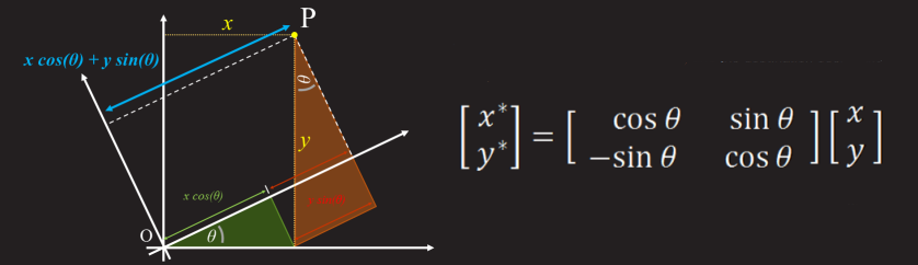
x '= cos (angle) * x - sin (angle) * y;
y '= sin (angle) * x + cos (angle) * y;
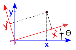
If you leave everything in this form, then the rotation will be centered at the origin. This rotation does not suit us, we need the picture to rotate around its axis with the center in the middle of the image. To do this, we need to carry out calculations relative to the center of the image.
parameter PRECISION   = 15;
parameter OUTPUT      = 12;
parameter INPUT       = 12;
parameter OUT_SIZE    = PRECISION + OUTPUT;
parameter BUS_MSB     = OUT_SIZE + 2;
wire [15:0] res_x = RES_X - 1'b1;
wire [15:0] res_y = RES_Y - 1'b1;
assign    dx = {1'b0, RES_X[11:1]};
assign    dy = {1'b0, RES_Y[11:1]};
always @(posedge clk) begin
    delta_x <= dx << PRECISION;
    delta_y <= dy << PRECISION;
еnd
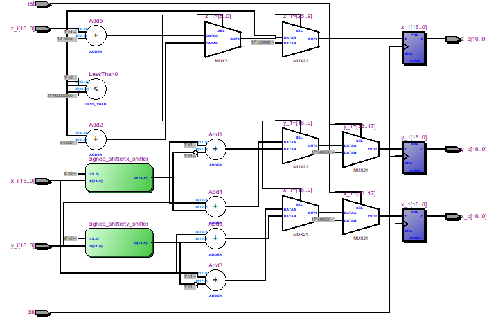
Next, we calculate the values cos (angle) * x, sin (angle) * x, cos (angle) * y, sin (angle) * y.
You can calculate it like this:
always @(posedge clk) begin
    mult_xcos <= (xi - dx) * COS;
    mult_xsin <= (xi - dx) * SIN;
    mult_ycos <= (yi - dy) * COS;
    mult_ysin <= (yi - dy) * SIN;
end
But I decided to use the lpm_mult megafunctions . Their use significantly increases Fmax .
reg signed [BUS_MSB: 0] tmp_x, tmp_y, mult_xsin, mult_xcos, mult_ysin, mult_ycos;
reg signed [BUS_MSB: 0] delta_x = 0, delta_y = 0;
wire signed [11:0] dx, dy;
reg signed [BUS_MSB: 0] mxsin, mxcos, mysin, mycos;
reg signed [11:0] ddx, ddy;
always @(posedge clk) begin
    ddx <= xi - dx;
    ddy <= yi - dy;
end
wire signed [BUS_MSB-1: 0] mult_xcos1;
wire signed [BUS_MSB-1: 0] mult_xsin1;
wire signed [BUS_MSB-1: 0] mult_ycos1;
wire signed [BUS_MSB-1: 0] mult_ysin1;
lpm_mult M1(.clock(clk), .dataa(COS), .datab(ddx), .result(mult_xcos1));
defparam M1.lpm_widtha = 17;
defparam M1.lpm_widthb = 12;
defparam M1.lpm_pipeline = 1;
defparam M1.lpm_representation = "SIGNED";
lpm_mult M2(.clock(clk), .dataa(SIN), .datab(ddx), .result(mult_xsin1));
defparam M2.lpm_widtha = 17;
defparam M2.lpm_widthb = 12;
defparam M2.lpm_pipeline = 1;
defparam M2.lpm_representation = "SIGNED";
lpm_mult M3(.clock(clk), .dataa(COS), .datab(ddy), .result(mult_ycos1));
defparam M3.lpm_widtha = 17;
defparam M3.lpm_widthb = 12;
defparam M3.lpm_pipeline = 1;
defparam M3.lpm_representation = "SIGNED";
lpm_mult M4(.clock(clk), .dataa(SIN), .datab(ddy), .result(mult_ysin1));
defparam M4.lpm_widtha = 17;
defparam M4.lpm_widthb = 12;
defparam M4.lpm_pipeline = 1;
defparam M4.lpm_representation = "SIGNED";
After multiplication, we get the products whose sign we need to change in each of the following quadrants:
always @(posedge clk) begin
    mxcos <= mult_xcos1;
    mxsin <= mult_xsin1;
    mycos <= mult_ycos1;
    mysin <= mult_ysin1;
    case (cordic_quadrant)
    2'd0: begin
        mxsin <= -mult_xsin1;
    end
    2'd1: begin
        mxcos <= -mult_xcos1;
        mxsin <= -mult_xsin1;
        mycos <= -mult_ycos1;
    end
    2'd2: begin
        mxcos <= -mult_xcos1;
        mysin <= -mult_ysin1;
        mycos <= -mult_ycos1;
    end
    2'd3: begin
        mysin <= -mult_ysin1;
    end
    endcase
end
Now the matter is left to the small thing - to calculate the pixel coordinates themselves:
/*
             I          II         III       IV
           +  +       +  -        -  -      -  -
           +  -       +  +        +  -      -  +
*/
always @(posedge clk) begin
    tmp_x <= delta_x + mxcos + mysin;
    tmp_y <= delta_y + mycos + mxsin;
end
wire [15:0] xo = tmp_x[BUS_MSB] ? 12'd0: tmp_x[OUT_SIZE-1:PRECISION];
wire [15:0] yo = tmp_y[BUS_MSB] ? 12'd0: tmp_y[OUT_SIZE-1:PRECISION];
Cut off pixels that go beyond the boundaries of the image:
wire [11:0] xo_t = (xo[11:0] > res_x[11:0]) ? 12'd0 : xo[11:0];
wire [11:0] yo_t = (yo[11:0] > res_y[11:0]) ? 12'd0 : yo[11:0];
And his address in memory:
//addr_out <= yo[11:0] * RES_X + xo[11:0];
And again, use lpm_mult:
reg [11:0] xo_r, yo_r;
always @(posedge clk) begin
	xo_r <= xo_t;
	yo_r <= yo_t;
end
wire [28:0] result;
lpm_mult M5(.clock(clk), .dataa(RES_X[11:0]), .datab(yo_r[11:0]), .result(result));
	defparam M5.lpm_widtha = 12;
	defparam M5.lpm_widthb = 12;
	defparam M5.lpm_pipeline = 1;
	defparam M5.lpm_representation = "UNSIGNED";
always @(posedge clk) addr_out <= result[22:0] + xo_r[11:0];
That's all, actually!
Method Issues
As I mentioned above, this approach has many drawbacks. Due to the calculation error, holes appear in the output picture; the larger the rotation angle, the more holes. This also happens because the dimensions of the new image are larger than the original. This effect is started by aliasing and there are methods to deal with it, for example, the median filter discussed in my previous article .
Before each subsequent frame, it would not hurt to clean the memory from the previous frame so that a new image is obtained on a clean background, but it takes time and you have to skip one frame.
The only advantage of the method is its ease of implementation and processing speed. coordinates are calculated on the fly.
That's what came out of it
Related Links
→ CORDIC in Russian
→ CORDIC for dummies
→ CORDIC FAQ
Project Archive in Quartus
→ Link to Yandex disk.