We make our USB sound card with galvanic isolation
It all started as usual,
Anyone interested under the cat.
Codec Chip Selection
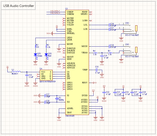
In general, I am not a fan of making electronics from anything, even for myself, especially from Chinese components with Ali, so first of all we go to the digikey and look for something. The first thought was to take a full-fledged codec chip and connect it to the STM32 , let alone USB . In principle, it is not difficult, but at some point I realized that I did not want to bother so much and decided to find something “all in one”. Google insistently issued CM108 from C-Media Electronics , a manufacturer in Taiwan. Well, okay, so be it.
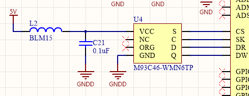
The codec demands an EEPROM for itself , and even offers a specific, analogue from STMicroelectronics M93C46-WMN6TPquickly found on the same digikey (Integrated Circuits (ICs)> Memory). Just in case, I connected its power through the filter so that nothing bad could happen to us in the codec's power.
Just quartz, and because I like to do everything in a smaller and more compact way, then I put the ABM3 series ( ABM3-12.000MHZ-B2-T ) 5 by 3.2 mm (do not put the same giant HC-49 )
Audio connectors

After looking for the connectors for headphones and microphone. I personally prefer CUI for audio and simple household 5.5 power connectors , I always put them, of course, search on digikey (Connectors, Interconnects> Barrel - Audio Connectors).
In my case, I already had a component in the library under SJ2-3574A-SMT . I used it before, you could choose multi-colored (I have a CUI ), but I didn’t want (I’m doing it for myself, somehow I’ll figure it out).
Usually capacitors are placed in series ( 0.47uF or 1uF , 4.7uF can be), it may be tantalum or ceramics, but it is best to use film. In the reference scheme, 470uF is offered in the datasheet , which is too much, choose 0.47uF (if you need very low bass then you can use 1uF ). Film capacitors are in SMD packages, which is very convenient, I put the ECP-U1C474MA5 in case 1206 .
Electrical isolation for power
And now the most interesting

CM108 has 2 modes, 100mA and 500mA , of course, I chose to be fatter so that with a span of 500mA * 5V = 2.5W , with a margin, we need to find a junction somewhere in 3W , set parameters - Board Mount> DC DC Converters) and see what is cheaper, just remembering to sift out manufacturers that you don’t trust. The choice fell on the CC3-0505SF-E from TDK (although I really wanted to deliver from Murata !). It is worth bold, 11 bucks, but nothing can be done.
After it, I put the filter, not forgetting about the capacitors 0.01uF and 0.001uFto weed out any HF heresy because it crawls through electroplating. Another 100uF electrolyte, it will definitely not be superfluous.
Interface decoupling
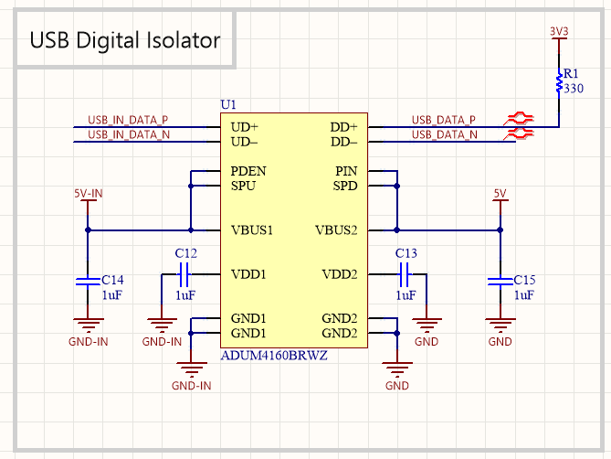
Isolation of power is good, but it does not hurt to untie the USB interface itself. In the Digital Isolators (Isolators> Digital Isolators) section, you can find the right one, I selected ADUM4160 from Analog Devices .
Do not forget to pull the DATA P on the USB interface to 3.3V , because this tells the host (PC) that the device is plugged into the port and we should start working with it, in an amicable way, this pull-up should be inside the chip, but for some reason it does not.
Well, the little things

The USB connector itself is of course from Molex , it is still possible from TE or Wurth . Or search from others, but I think that such connectors are better to choose from these three, the rest are good, but in another.
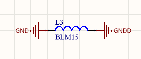
I also decided that if so much money was spent on clean food, then everything must be done well until the end, and the denouement of digital land and analog is no exception. Moreover, instead of the usual jumper on the board, I put the BLM15 filter (when distributing the board, the division of the earth is better to move closer to the main ground, that is, to the GND output of our isolator on the power supply, digital and analog ground should diverge)
Conclusion

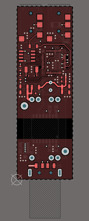
Well, that's all, I spread the board in 4 layers of the standard class, after preparation for production it will cost about 130 rubles. Also 4 layers are better in terms of the fact that polygons of food, earth and digital land are better to do proper polygons proper, in a good way, each layer has its own layer, but I have food and digital earth on one.
It took about an hour and a half from the idea to the full layout. The fee came out in size 22 by 66 mm.
Honestly, while I was writing an article I had no idea to order a fee (well, as always), so let it be at least an article.
PS Often I kill time like this by planting different projects, from simple wireless charging to wiring processors and ... leaving them gathering dust in the hard drive folder. I lose interest in most cases (and because it's free, no need to spend money on components). If you are interested in such articles, then you can offer your ideas for the following
PPS projects. Due to the fact that the board did not order and did not check, errors are possible.