DOCSIS 3.1 - how to achieve maximum throughput
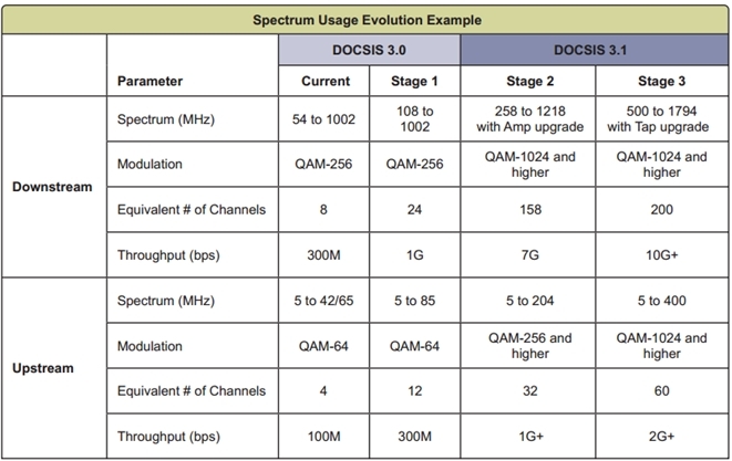
The new version of the DOCSIS specification - DOCSIS 3.1, completely changed the principles of DOCSIS, increasing the channel throughput by 50%, performance up to 10 Gb / s in the forward channel and up to 2 Gb / s in the reverse - speeds comparable to data transmission over fiber.
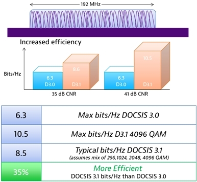
DOCSIS 3.1 provides more bits per 1 hertz compared to DOCSIS 3.0 with the same signal-to-noise ratio.
The DOCSIS 3.1 specification was released and successfully tested in laboratory conditions in 2015. At the beginning of 2016, 5 new cable modems supporting the DOCSIS 3.1 standard were certified, and providers around the world began to implement and test equipment of this standard.
But what makes DOCSIS 3.1 unique compared to earlier versions and how will the testing methods change in connection with this? This article discusses the two main technologies used in the latest version of the specification: orthogonal frequency-division multiplexing (OFDM) and low density parity check (LDPC) code. The article also describes methods to achieve maximum levels of performance.
The easiest way to understand OFDM is to remember how DOCSIS 3.0 works. There, for one forward channel, one carrier frequency with a band of 6 MHz (8 MHz in Europe) is used. Single-carrier QAM (SC-QAM) is used to modulate this frequency and the characters are transmitted at that frequency strictly sequentially. If there are problems with signal reception, then the modulation must be reduced - not only for this frequency, but also for all other channels in the network. This means that the modulation must be optimized for the worst part of the coaxial network.
Unlike SC-QAM, OFDM uses a bandwidth of 24 to 192 MHz. Up to 8 thousand subcarriers with a width of 25 to 50 kHz each can be placed inside this band. ( More precisely, 7680 subcarriers of 25 kHz or 3840 subcarriers of 50 kHz - approx. Translator) All subcarriers are synchronized with each other in time and form a single set of characters. These characters, in turn, are distributed across subcarriers and time slots and transmit codewords.
The main advantage of this approach is that symbols are transmitted simultaneously at different frequencies. This creates some unique opportunities. So, if interference occurs on one subcarrier, OFDM simply eliminates it by combining adjacent frequencies. This allows you to continue transmitting data with the optimal level of performance. ( In addition, this transmission method is much less sensitive to narrowband and pulsed interference, since they affect only some subcarriers, whereas in the case of a normal signal, interference affects its entire spectrum - approx. Translator )
Since the modulation type in OFDM is set for a certain period of time, this technology allows you to control the mutual phase ratio of the subcarriers. If one subcarrier is at its peak, then the neighboring one can be out of phase, i.e. at zero. This reduces the interference between adjacent subcarriers and allows them to use higher modulation levels and, accordingly, increase the overall network bandwidth. Instead of using one modulation level for the entire range, OFDM allows you to use different modulation levels for each subcarrier. In addition, you can create modulation profiles in such a way as to set individual modulation levels for all subcarriers and to have several such profiles.

Modulation - SC QAM
Dedicated channels with a bandwidth of 6 MHz (8 MHz in Europe).
Each frequency channel is independent of the others.
Symbols in one channel are transmitted sequentially.
Modulation is optimized for the worst part of the cable network.
Take one subcarrier as an example. Each profile has its own modulation level (for example, 64 QAM, 1024 QAM, 2048 QAM or 4096 QAM). OFDM can use the highest level profile for a given HFC network segment. In one segment it will be 4096 QAM, in another it can be 1024 QAM. In the third segment at this frequency, there may be too much interference and this part of the spectrum will be completely excluded from the profile, etc.
Now let's see what happens on this subcarrier to understand the operation of all 8000. A separate profile describes a separate subcarrier in order to achieve its maximum performance in each time period.
As mentioned above, all subcarriers are combined among themselves for the joint transmission of characters from which codewords are formed. Subcarriers are associated with each symbol of the codeword and their modulation level is described by the profile. Profiles, in turn, are assigned letter designations (for example, A, B, C, and D). Thus, it turns out that optimization is performed not only for each subcarrier individually, but for all 8000 subcarriers in the complex.
Instead of optimizing the modulation for the worst part of the network, it can be optimized for the best part at any given time. This makes DOCSIS 3.1 a much more efficient technology than its predecessors. Where a channel on DOCSIS 3.0 could transmit 6.3 bits at 1 Hz, DOCSIS 3.1 can reach 10.5 bits at 1 Hz using 4096 QAM modulation. In a more typical case, when several levels of modulation are used simultaneously, DOCSIS 3.1 can reach 8.5 bits at 1 Hz, providing an increase in efficiency by 35% without changes in the HFC network.
Improvements made using OFDM would not have been possible without error correction algorithms. DOCSIS 3.0 uses a forward error correction algorithm with a Reed-Solomon code (FEC) and measures the level of bit errors (BER). BER refers to a single carrier, and OFDM uses a lot. Due to the fact that OFDM distributes the transmitted data across multiple subcarriers, the use of BER no longer makes sense.
DOCSIS 3.1 uses LPDC instead of FEC. This algorithm works over the entire range and evaluates errors not of individual bits, but of the entire code words. If such an error can be corrected, LPDC automatically does this, which allows the use of higher levels of modulation and significantly reduces the need for retransmission of code words. LPDC brings channel capacity closer to the theoretical limits described by Shannon's theorem.
But LDPC has one drawback. Since this algorithm changes the settings in real time, the system can achieve maximum values in terms of power and modulation levels by correcting errors that occur. This means that the network will degrade unnoticed by the operator and at some point the errors will become uncorrectable, and users will notice a decrease in the quality of the service. In order to avoid such a situation, it is necessary to test the system more thoroughly.
For testing to be successful, it is very important to understand what OFDM consists of. At the heart of everything lies the PLC level - PHY link channel, which contains information on how to decode an OFDM signal. Without this level, the modem will not be able to “see” the OFDM carrier and understand how to decode it. The level above is a pointer to the next codeword (next codeword pointer - NCP), which tells the modem which codeword to read next and which profile to use to decode each codeword. Next is profile A. This is a boot profile that every DOCSIS 3.1 modem must be able to use in order to “understand” higher levels of QAM modulation in other profiles.
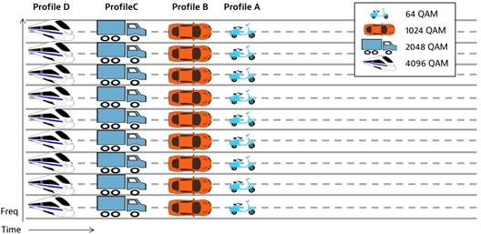
Profiles are a simplified situation. For simplicity, we assume that profiles use the same modulation on all subcarriers.
The parameters of power levels, MER and noise in profile A are selected for reliable OFDM operation. If this profile works, then standard profiles B, C and D can be used further. Profiles different from them can be created by manufacturers of CMTS and cable modems at their discretion and their number is not limited in any way.
When transmitting PLC level information, it is important to achieve the absence of uncorrectable codeword errors (CWE). At the PLC level, the transmission of information should be as reliable as possible, so the power level and MER must be strictly in the specified range. To do this, the parameters of this level should be strictly fixed - the DOCSIS 3.1 specification limits the use of only BPSK or 16 QAM for PLCs.
If at the PLC level everything works without errors, the NCP parameters are also fixed and should not allow for uncorrectable errors (CWE). If there is a loss of messages at this level, the modem will re-request information or, even worse, there will be no communication at all. In DOCSIS 3.1, only QPSK, 16 QAM, or 64 QAM can be used for NCP transmission.
Since profile A is bootable, it is assigned lower levels of modulation compared to others: QAM 16 and QAM 64. This is done so that all modems can work even in the worst part of the cable network. A signal with a lower modulation level can operate at lower power levels and MER. Just like the two previous levels, profile A must have fixed parameters and avoid uncorrectable errors. If uncorrectable errors appear, the modem will switch to DCOSIS 3.0 mode and there will be no increase in efficiency. Profile A can work at higher modulation levels, while correcting CWE errors are allowed, this is normal, the main thing is that there are no uncorrectable ones.
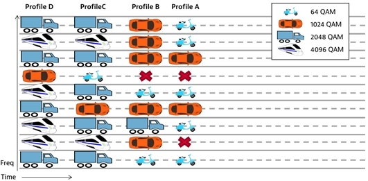
Profiles are the real situation. OFDM allows you to exclude specific subcarriers and allows everyone to have different modulation levels for different subcarriers. This optimizes the overall channel throughput - each profile has its own exceptions.
When all 3 levels work within the given limits, you can look at the total bandwidth of the channel. One of the errors at this stage may be the measurement of the signal level in the entire 192 MHz band. It must be remembered that the total power in this band of the spectrum is equal to the power of 6 MHz signal, taking into account the bandwidth. Thus, the total power of the OFDM signal is very different from the power of a single carrier with a width of 6 (8) MHz. In order to fine-tune the OFDM signal power, all levels must be measured relative to the signal power with a bandwidth of 6 MHz.
OFDM has some more unique features. The levels of the first and last 6 MHz in a given OFDM signal band will be approximately 0.8 dB lower than the levels of the remaining subcarriers due to a fall in the guard band. This becomes important when standard instruments are used for measurement, or when power is measured in a frequency range of 6 MHz that is allocated from the general range. In addition, the carrier with the PLC is approximately 0.8 dB higher than other subcarriers due to additional pilot signals and transmitted data. Thus, the total flatness of the OFDM signal compared to the standard 6 MHz signal will fluctuate within 1.6 dB due to the initial and final decays and the influence of the PLC.
In order for OFDM to work with peak performance, the average power level should not go beyond the specified limits, the MER should be good and the noise levels should be minimal. Noise greatly affects the OFDM signal and can lead to the fact that profiles with high modulation levels will not be used at all.
If all these requirements are met, then it becomes possible to use profiles with high levels of modulation. It is important that the parameters are locked (locked) within the profile. Profiles with a high level of modulation may have some correctable errors (CWE), since this is not as critical as for lower levels, but uncorrectable errors will lead to the fact that maximum performance will not be achieved. For example, if profile C has uncorrectable errors, profiles D and higher cannot use higher modulation than profile C. To achieve high levels of modulation, the HFC network must be clean and prevent uncorrectable errors (which is also true for earlier versions DOCSIS).
DOCSIS 3.1 uses OFDMA for the return channel - Orthogonal Frequency-Division Multiple Access.
Separate subcarriers in OFDMA can be turned off to provide backward compatibility with DOCSIS 2 / 3.0 channels
DOCSIS 3.1 solves the main dilemma faced by operators for many years: “Spend money on a complete upgrade of the entire cable network or gradually make changes to the existing network?” Using OFDM and LDPC technologies, operators can significantly increase network bandwidth with minimal modernization .
A small upgrade of the physical structure of the network is enough to increase its efficiency (speed and throughput) by 35% using DOCSIS 3.1. It will also give operators additional time for further gradual modernization, which, in turn, will provide an opportunity to further increase throughput.
However, operators need to be fairly careful about implementing and testing DOCSIS 3.1. If this is done incorrectly, then there will be no improvement compared to DOCSIS 3.0.
Using the practices described in this article will make sure that DOCSIS 3.1 is used as efficiently as possible, reducing the number of visits of repair teams and providing high quality service to customers.
The next step will be the introduction of the DOCSIS 3.1 Full duplex specification , which will provide symmetrical data transfer at 10Gb / s speeds both in the forward and reverse channels.
The original article is here .
DOCSIS 3.1 provides more bits per 1 hertz compared to DOCSIS 3.0 with the same signal-to-noise ratio.
The DOCSIS 3.1 specification was released and successfully tested in laboratory conditions in 2015. At the beginning of 2016, 5 new cable modems supporting the DOCSIS 3.1 standard were certified, and providers around the world began to implement and test equipment of this standard.
But what makes DOCSIS 3.1 unique compared to earlier versions and how will the testing methods change in connection with this? This article discusses the two main technologies used in the latest version of the specification: orthogonal frequency-division multiplexing (OFDM) and low density parity check (LDPC) code. The article also describes methods to achieve maximum levels of performance.
Orthogonal Frequency Domain Multiplexing
The easiest way to understand OFDM is to remember how DOCSIS 3.0 works. There, for one forward channel, one carrier frequency with a band of 6 MHz (8 MHz in Europe) is used. Single-carrier QAM (SC-QAM) is used to modulate this frequency and the characters are transmitted at that frequency strictly sequentially. If there are problems with signal reception, then the modulation must be reduced - not only for this frequency, but also for all other channels in the network. This means that the modulation must be optimized for the worst part of the coaxial network.
Unlike SC-QAM, OFDM uses a bandwidth of 24 to 192 MHz. Up to 8 thousand subcarriers with a width of 25 to 50 kHz each can be placed inside this band. ( More precisely, 7680 subcarriers of 25 kHz or 3840 subcarriers of 50 kHz - approx. Translator) All subcarriers are synchronized with each other in time and form a single set of characters. These characters, in turn, are distributed across subcarriers and time slots and transmit codewords.
The main advantage of this approach is that symbols are transmitted simultaneously at different frequencies. This creates some unique opportunities. So, if interference occurs on one subcarrier, OFDM simply eliminates it by combining adjacent frequencies. This allows you to continue transmitting data with the optimal level of performance. ( In addition, this transmission method is much less sensitive to narrowband and pulsed interference, since they affect only some subcarriers, whereas in the case of a normal signal, interference affects its entire spectrum - approx. Translator )
Since the modulation type in OFDM is set for a certain period of time, this technology allows you to control the mutual phase ratio of the subcarriers. If one subcarrier is at its peak, then the neighboring one can be out of phase, i.e. at zero. This reduces the interference between adjacent subcarriers and allows them to use higher modulation levels and, accordingly, increase the overall network bandwidth. Instead of using one modulation level for the entire range, OFDM allows you to use different modulation levels for each subcarrier. In addition, you can create modulation profiles in such a way as to set individual modulation levels for all subcarriers and to have several such profiles.
Modulation - SC QAM
Dedicated channels with a bandwidth of 6 MHz (8 MHz in Europe).
Each frequency channel is independent of the others.
Symbols in one channel are transmitted sequentially.
Modulation is optimized for the worst part of the cable network.
Take one subcarrier as an example. Each profile has its own modulation level (for example, 64 QAM, 1024 QAM, 2048 QAM or 4096 QAM). OFDM can use the highest level profile for a given HFC network segment. In one segment it will be 4096 QAM, in another it can be 1024 QAM. In the third segment at this frequency, there may be too much interference and this part of the spectrum will be completely excluded from the profile, etc.
Now let's see what happens on this subcarrier to understand the operation of all 8000. A separate profile describes a separate subcarrier in order to achieve its maximum performance in each time period.
As mentioned above, all subcarriers are combined among themselves for the joint transmission of characters from which codewords are formed. Subcarriers are associated with each symbol of the codeword and their modulation level is described by the profile. Profiles, in turn, are assigned letter designations (for example, A, B, C, and D). Thus, it turns out that optimization is performed not only for each subcarrier individually, but for all 8000 subcarriers in the complex.
Instead of optimizing the modulation for the worst part of the network, it can be optimized for the best part at any given time. This makes DOCSIS 3.1 a much more efficient technology than its predecessors. Where a channel on DOCSIS 3.0 could transmit 6.3 bits at 1 Hz, DOCSIS 3.1 can reach 10.5 bits at 1 Hz using 4096 QAM modulation. In a more typical case, when several levels of modulation are used simultaneously, DOCSIS 3.1 can reach 8.5 bits at 1 Hz, providing an increase in efficiency by 35% without changes in the HFC network.
Low density check
Improvements made using OFDM would not have been possible without error correction algorithms. DOCSIS 3.0 uses a forward error correction algorithm with a Reed-Solomon code (FEC) and measures the level of bit errors (BER). BER refers to a single carrier, and OFDM uses a lot. Due to the fact that OFDM distributes the transmitted data across multiple subcarriers, the use of BER no longer makes sense.
DOCSIS 3.1 uses LPDC instead of FEC. This algorithm works over the entire range and evaluates errors not of individual bits, but of the entire code words. If such an error can be corrected, LPDC automatically does this, which allows the use of higher levels of modulation and significantly reduces the need for retransmission of code words. LPDC brings channel capacity closer to the theoretical limits described by Shannon's theorem.
But LDPC has one drawback. Since this algorithm changes the settings in real time, the system can achieve maximum values in terms of power and modulation levels by correcting errors that occur. This means that the network will degrade unnoticed by the operator and at some point the errors will become uncorrectable, and users will notice a decrease in the quality of the service. In order to avoid such a situation, it is necessary to test the system more thoroughly.
Achieving maximum network bandwidth
For testing to be successful, it is very important to understand what OFDM consists of. At the heart of everything lies the PLC level - PHY link channel, which contains information on how to decode an OFDM signal. Without this level, the modem will not be able to “see” the OFDM carrier and understand how to decode it. The level above is a pointer to the next codeword (next codeword pointer - NCP), which tells the modem which codeword to read next and which profile to use to decode each codeword. Next is profile A. This is a boot profile that every DOCSIS 3.1 modem must be able to use in order to “understand” higher levels of QAM modulation in other profiles.
Profiles are a simplified situation. For simplicity, we assume that profiles use the same modulation on all subcarriers.
The parameters of power levels, MER and noise in profile A are selected for reliable OFDM operation. If this profile works, then standard profiles B, C and D can be used further. Profiles different from them can be created by manufacturers of CMTS and cable modems at their discretion and their number is not limited in any way.
When transmitting PLC level information, it is important to achieve the absence of uncorrectable codeword errors (CWE). At the PLC level, the transmission of information should be as reliable as possible, so the power level and MER must be strictly in the specified range. To do this, the parameters of this level should be strictly fixed - the DOCSIS 3.1 specification limits the use of only BPSK or 16 QAM for PLCs.
If at the PLC level everything works without errors, the NCP parameters are also fixed and should not allow for uncorrectable errors (CWE). If there is a loss of messages at this level, the modem will re-request information or, even worse, there will be no communication at all. In DOCSIS 3.1, only QPSK, 16 QAM, or 64 QAM can be used for NCP transmission.
Since profile A is bootable, it is assigned lower levels of modulation compared to others: QAM 16 and QAM 64. This is done so that all modems can work even in the worst part of the cable network. A signal with a lower modulation level can operate at lower power levels and MER. Just like the two previous levels, profile A must have fixed parameters and avoid uncorrectable errors. If uncorrectable errors appear, the modem will switch to DCOSIS 3.0 mode and there will be no increase in efficiency. Profile A can work at higher modulation levels, while correcting CWE errors are allowed, this is normal, the main thing is that there are no uncorrectable ones.
Profiles are the real situation. OFDM allows you to exclude specific subcarriers and allows everyone to have different modulation levels for different subcarriers. This optimizes the overall channel throughput - each profile has its own exceptions.
When all 3 levels work within the given limits, you can look at the total bandwidth of the channel. One of the errors at this stage may be the measurement of the signal level in the entire 192 MHz band. It must be remembered that the total power in this band of the spectrum is equal to the power of 6 MHz signal, taking into account the bandwidth. Thus, the total power of the OFDM signal is very different from the power of a single carrier with a width of 6 (8) MHz. In order to fine-tune the OFDM signal power, all levels must be measured relative to the signal power with a bandwidth of 6 MHz.
OFDM has some more unique features. The levels of the first and last 6 MHz in a given OFDM signal band will be approximately 0.8 dB lower than the levels of the remaining subcarriers due to a fall in the guard band. This becomes important when standard instruments are used for measurement, or when power is measured in a frequency range of 6 MHz that is allocated from the general range. In addition, the carrier with the PLC is approximately 0.8 dB higher than other subcarriers due to additional pilot signals and transmitted data. Thus, the total flatness of the OFDM signal compared to the standard 6 MHz signal will fluctuate within 1.6 dB due to the initial and final decays and the influence of the PLC.
In order for OFDM to work with peak performance, the average power level should not go beyond the specified limits, the MER should be good and the noise levels should be minimal. Noise greatly affects the OFDM signal and can lead to the fact that profiles with high modulation levels will not be used at all.
If all these requirements are met, then it becomes possible to use profiles with high levels of modulation. It is important that the parameters are locked (locked) within the profile. Profiles with a high level of modulation may have some correctable errors (CWE), since this is not as critical as for lower levels, but uncorrectable errors will lead to the fact that maximum performance will not be achieved. For example, if profile C has uncorrectable errors, profiles D and higher cannot use higher modulation than profile C. To achieve high levels of modulation, the HFC network must be clean and prevent uncorrectable errors (which is also true for earlier versions DOCSIS).
What about Upstream?
DOCSIS 3.1 uses OFDMA for the return channel - Orthogonal Frequency-Division Multiple Access.
Separate subcarriers in OFDMA can be turned off to provide backward compatibility with DOCSIS 2 / 3.0 channels
DOCSIS 3.0 vs. DOCSIS 3.1 Comparison Chart
Conclusion
DOCSIS 3.1 solves the main dilemma faced by operators for many years: “Spend money on a complete upgrade of the entire cable network or gradually make changes to the existing network?” Using OFDM and LDPC technologies, operators can significantly increase network bandwidth with minimal modernization .
A small upgrade of the physical structure of the network is enough to increase its efficiency (speed and throughput) by 35% using DOCSIS 3.1. It will also give operators additional time for further gradual modernization, which, in turn, will provide an opportunity to further increase throughput.
However, operators need to be fairly careful about implementing and testing DOCSIS 3.1. If this is done incorrectly, then there will be no improvement compared to DOCSIS 3.0.
Using the practices described in this article will make sure that DOCSIS 3.1 is used as efficiently as possible, reducing the number of visits of repair teams and providing high quality service to customers.
What's next?
The next step will be the introduction of the DOCSIS 3.1 Full duplex specification , which will provide symmetrical data transfer at 10Gb / s speeds both in the forward and reverse channels.
The original article is here .