Getting FPGA to Python
FPGA technology (FPGA) is currently gaining great popularity. A growing number of applications: in addition to digital signal processing, FPGAs are used to accelerate machine learning, in blockchain technology, video processing, and IoT.
This technology has one significant drawback: for programming, quite complex and specific languages for describing digital equipment Verilog and VHDL are used. This makes it difficult for a newcomer to enter the FPGA and it is difficult for an employer to find a specialist with this specific knowledge of the labor market. On the other hand, the popular high-level programming language Python with the framework MyHDLmake FPGA programming easy and fun. Moreover, people who know Python are an order of magnitude more specialists who own Verilog / VHDL. With a series of articles I want to show how easy it is to get into the FPGA area, knowing Python and start doing real complex FPGA projects in this language. I note that python FPGA is not executed directly, but is a tool for generating firmware.
First of all, we need python version 3.6 itself (hereinafter, all operations are performed in Ubuntu 18.04 OS).
Install myhdl:
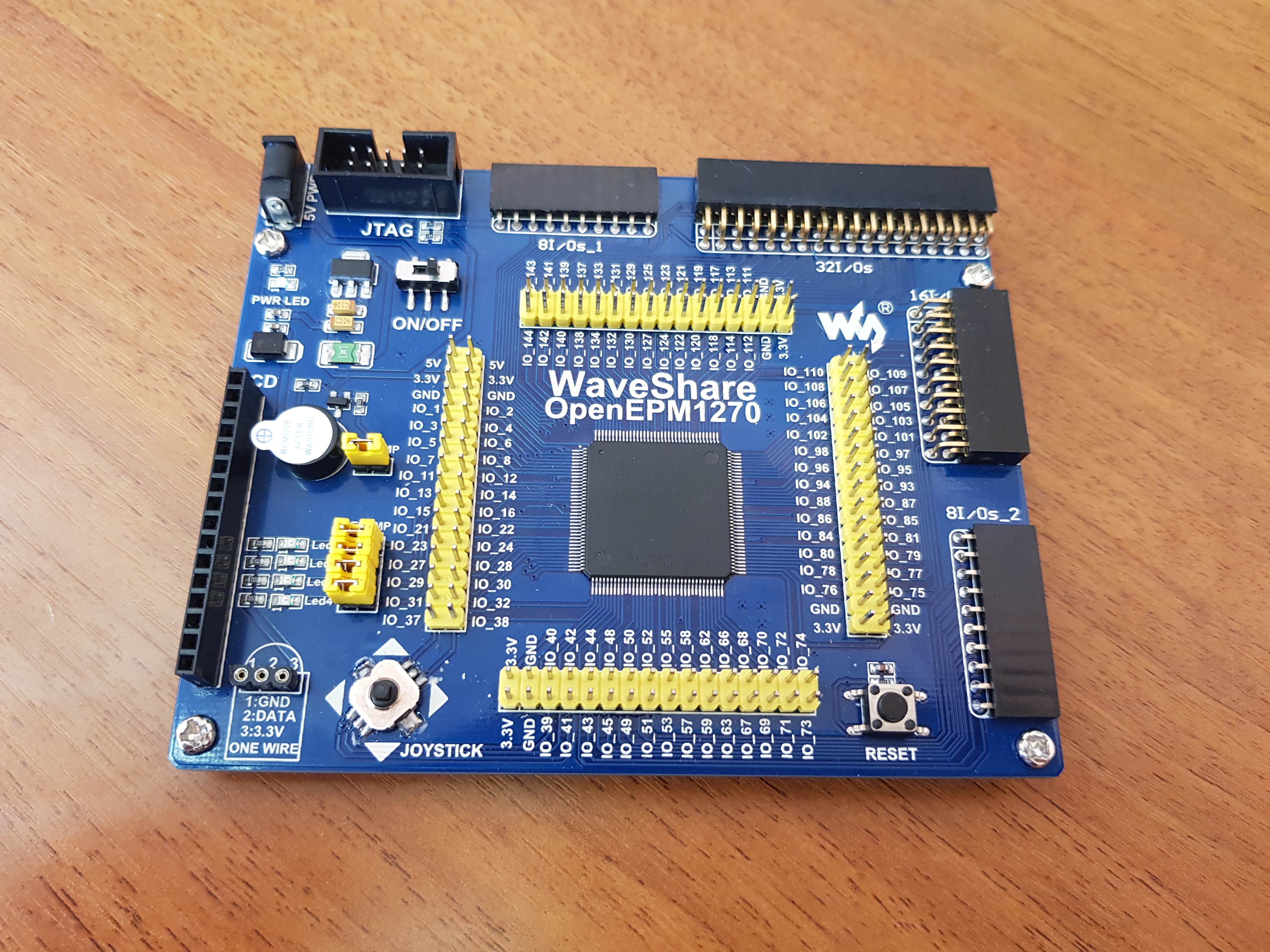
As “Hello World!”, We will write a simple program that causes the LEDs to light up by pressing a button. In the microprocessor world, “Hello World!” Is a program that flashes with a single LED, while in the FPGA world, Hello World is the blinking of a thousand LEDs. There are only four LEDs on the board, so only they will blink depending on the button press. It is important to note that all the code in the FPGA, unlike microcontrollers, is executed simultaneously, all the diodes are lit and extinguished simultaneously. And not consistently in the case of microcontrollers. In the role of the experimental one, the WaveShare OpenEPM1270 board with Altera Max II EPM1270T144C5 plis is used on board.
Create a new python file:
To find out if our code works correctly, you need a verification tool. In fact, any program for FPGA is a digital signal processor, respectively, the developer needs to make sure that he has correctly indicated what to do with the chip. This is done through a simulation, for this you need to install a program that will display the processed signals. There are quite a few such programs, but in my opinion, the best so far is free GTKWave. Put from the terminal:
Next, in the file with the firmware, you should describe the test environment. This is also a Python function:
Here the test environment generates a random sequence of zeros and ones (using the Python module random).
And we initialize the simulator, dragging the environment function test_inverter there. Thus, the result is the nested doll inverter → test_inverter → simulate (time in arbitrary units).
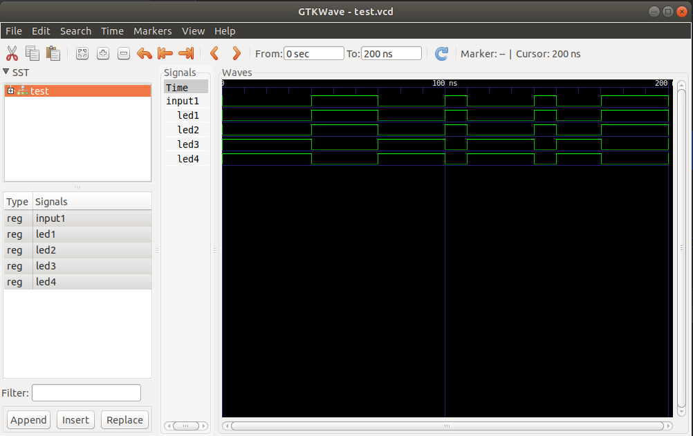
After running the script in the working folder, create a .vcd file and skip it through gtkwave, in the terminal: gtkwave test_invereter.vcd.
As a result, a random sequence of input1 input signals was generated, and how the led_blinker function processed these signals.
After we made sure that the logic worked exactly as we wanted, then this function should be thrown into the FPGA. I’m used to working with Intel (previously Altera) microcircuits, this sequence of actions is similar for other manufacturers' microcircuits with corresponding CAD systems. On the FPGA chip, a binary file is created that the compiler of the chip manufacturer creates, for Intel it is Quartus, for Xilinx Vivado. Compilers can only work with code in VHDL / Verilog, so Python code should be translated into any of these languages (it doesn’t matter to which).
In this example, the code is translated to Verilog. The result is in the file led_blinker.v, and it will have to be given to Quartus to generate the FPGA firmware:
In this approach to the development of FPGA firmware, you can ignore this file and simply throw it into Quartus.
You can download Quartus from fpgasoftware.intel.com , you need a free Lite version, which will be enough for us. We download the basic version of the size of 9 GB.
Installing Quartus should be easy for a regular Linux user. After installation, you need to set some parameters in the system so that you can use the device for stitching the program FPGA - programmer:
1. Create a udev rule. To do this, create a new file /etc/udev/rules.d/51-altera-usb-blaster.rules with the following content:
Reboot udev using udevadm:
2. We allow non-root access to the USB-Blaster device. To do this, create the file /etc/udev/rules.d/altera-usb-blaster.rules with the line:
This gives rw-rw-rw- access to the programmer.
3. Configure jtagd. Quartus uses the jtagd daemon, which connects software to a programmer device, to work. Copy the description from your Quartus directory:
Launch Quartus and create a new project “File” - “New project wizard”, type the name of the project.
Next, click Next. And in the Add Files menu, we connect the generated verilog file with the .v extension. Thus, if the verilog file is edited from the python file, it will automatically be picked up by Quartus, Next we get to the device selection menu, in our case it is MAX II EMP1270T144C5 and a couple more times next. Project created.
In Project Navigator, go to the file menu and right-click to set our verilog file "Set as top-level entity".
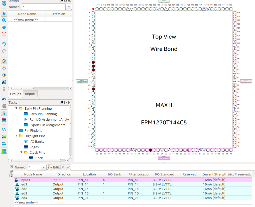
Compile the project. Now in the “Assignments-Pin Planner” menu we configure the pins on the microcircuit:
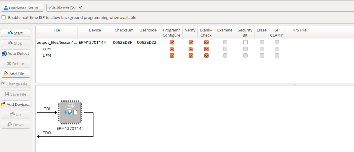
Compile again. Now everything is ready for programming: Tools-Programmer. We connect the programmer and power to the board, in the Hardware Setup we select our USB-Blaster, set the checkboxes as shown in the figure and Start.
After the Programmer reported Successful. You can see the result on the board:
This lesson describes how to create a working environment and the first simple FPGA project in the Python programming language.
Reviewed by:
This technology has one significant drawback: for programming, quite complex and specific languages for describing digital equipment Verilog and VHDL are used. This makes it difficult for a newcomer to enter the FPGA and it is difficult for an employer to find a specialist with this specific knowledge of the labor market. On the other hand, the popular high-level programming language Python with the framework MyHDLmake FPGA programming easy and fun. Moreover, people who know Python are an order of magnitude more specialists who own Verilog / VHDL. With a series of articles I want to show how easy it is to get into the FPGA area, knowing Python and start doing real complex FPGA projects in this language. I note that python FPGA is not executed directly, but is a tool for generating firmware.
First of all, we need python version 3.6 itself (hereinafter, all operations are performed in Ubuntu 18.04 OS).
Install myhdl:
pip3 install myhdlAs “Hello World!”, We will write a simple program that causes the LEDs to light up by pressing a button. In the microprocessor world, “Hello World!” Is a program that flashes with a single LED, while in the FPGA world, Hello World is the blinking of a thousand LEDs. There are only four LEDs on the board, so only they will blink depending on the button press. It is important to note that all the code in the FPGA, unlike microcontrollers, is executed simultaneously, all the diodes are lit and extinguished simultaneously. And not consistently in the case of microcontrollers. In the role of the experimental one, the WaveShare OpenEPM1270 board with Altera Max II EPM1270T144C5 plis is used on board.
Create a new python file:
from myhdl import *
from random import randrange
defled_blinker(input1, led1, led2, led3, led4):    @always_combdefon_off_led():if input1 == 1:
            led1.next = 1
            led2.next = 1
            led3.next = 0
            led4.next = 0else:
            led1.next = 0
            led2.next = 0
            led3.next = 1
            led4.next = 1return on_off_led
To find out if our code works correctly, you need a verification tool. In fact, any program for FPGA is a digital signal processor, respectively, the developer needs to make sure that he has correctly indicated what to do with the chip. This is done through a simulation, for this you need to install a program that will display the processed signals. There are quite a few such programs, but in my opinion, the best so far is free GTKWave. Put from the terminal:
sudo apt-get install gtkwaveNext, in the file with the firmware, you should describe the test environment. This is also a Python function:
deftest():
    input1, led1, led2, led3, led4 = [Signal(bool(0)) for i in range(5)]
    test = led_blinker(input1, led1, led2, led3, led4)
    @always(delay(10))defgen():
        input1.next = randrange(2)
return test, gen
Here the test environment generates a random sequence of zeros and ones (using the Python module random).
defsimulate(timesteps):
    tb = traceSignals(test)
    sim = Simulation(tb)
    sim.run(timesteps)
And we initialize the simulator, dragging the environment function test_inverter there. Thus, the result is the nested doll inverter → test_inverter → simulate (time in arbitrary units).
After running the script in the working folder, create a .vcd file and skip it through gtkwave, in the terminal: gtkwave test_invereter.vcd.
As a result, a random sequence of input1 input signals was generated, and how the led_blinker function processed these signals.
After we made sure that the logic worked exactly as we wanted, then this function should be thrown into the FPGA. I’m used to working with Intel (previously Altera) microcircuits, this sequence of actions is similar for other manufacturers' microcircuits with corresponding CAD systems. On the FPGA chip, a binary file is created that the compiler of the chip manufacturer creates, for Intel it is Quartus, for Xilinx Vivado. Compilers can only work with code in VHDL / Verilog, so Python code should be translated into any of these languages (it doesn’t matter to which).
defconvert():
    input1, led1, led2, led3, led4 = [Signal(bool(0)) for i in range(5)]
    toVerilog(led_blinker, input1, led1, led2, led3, led4)
convert()
In this example, the code is translated to Verilog. The result is in the file led_blinker.v, and it will have to be given to Quartus to generate the FPGA firmware:
module led_blinker (
    input1,
    led1,
    led2,
    led3,
    led4
);
input input1;
output led1;
reg led1;
output led2;
reg led2;
output led3;
reg led3;
output led4;
reg led4;
always @(input1) begin: LED_BLINKER_ON_OFF_LED
    if ((input1 == 1)) begin
        led1 = 1;
        led2 = 1;
        led3 = 0;
        led4 = 0;
    endelsebegin
        led1 = 0;
        led2 = 0;
        led3 = 1;
        led4 = 1;
    endend
endmodule
In this approach to the development of FPGA firmware, you can ignore this file and simply throw it into Quartus.
You can download Quartus from fpgasoftware.intel.com , you need a free Lite version, which will be enough for us. We download the basic version of the size of 9 GB.
Installing Quartus should be easy for a regular Linux user. After installation, you need to set some parameters in the system so that you can use the device for stitching the program FPGA - programmer:
1. Create a udev rule. To do this, create a new file /etc/udev/rules.d/51-altera-usb-blaster.rules with the following content:
# USB-Blaster
SUBSYSTEM=="usb", ATTR{idVendor}=="09fb", ATTR{idProduct}=="6001", MODE="0666"
SUBSYSTEM=="usb", ATTR{idVendor}=="09fb", ATTR{idProduct}=="6002", MODE="0666"
SUBSYSTEM=="usb", ATTR{idVendor}=="09fb", ATTR{idProduct}=="6003", MODE="0666"# USB-Blaster II
SUBSYSTEM=="usb", ATTR{idVendor}=="09fb", ATTR{idProduct}=="6010", MODE="0666"
SUBSYSTEM=="usb", ATTR{idVendor}=="09fb", ATTR{idProduct}=="6810", MODE="0666"
Reboot udev using udevadm:
sudo udevadm control --reload2. We allow non-root access to the USB-Blaster device. To do this, create the file /etc/udev/rules.d/altera-usb-blaster.rules with the line:
ATTR{idVendor}=="09fb", ATTR{idProduct}=="6001", MODE="666"This gives rw-rw-rw- access to the programmer.
3. Configure jtagd. Quartus uses the jtagd daemon, which connects software to a programmer device, to work. Copy the description from your Quartus directory:
sudo mkdir /etc/jtagd
sudo cp <Quartus install path>/quartus/linux64/pgm_parts.txt /etc/jtagd/jtagd.pgm_parts
Launch Quartus and create a new project “File” - “New project wizard”, type the name of the project.
Next, click Next. And in the Add Files menu, we connect the generated verilog file with the .v extension. Thus, if the verilog file is edited from the python file, it will automatically be picked up by Quartus, Next we get to the device selection menu, in our case it is MAX II EMP1270T144C5 and a couple more times next. Project created.
In Project Navigator, go to the file menu and right-click to set our verilog file "Set as top-level entity".
Compile the project. Now in the “Assignments-Pin Planner” menu we configure the pins on the microcircuit:
Compile again. Now everything is ready for programming: Tools-Programmer. We connect the programmer and power to the board, in the Hardware Setup we select our USB-Blaster, set the checkboxes as shown in the figure and Start.
After the Programmer reported Successful. You can see the result on the board:
Conclusion
This lesson describes how to create a working environment and the first simple FPGA project in the Python programming language.
Reviewed by:
- How to install:
- myHDL;
- GTKWave;
- Quartus;
- Configured USB Blaster programmer in Ubuntu;
- Developed a project for FPGA in python;
- Produced testing and verification of the project;
- Compiled project for FPGA;
- Loaded project on FPGA.