First Altera FPGA project and USB-Blaster connection in Linux
- Tutorial
We continue to develop Altera FPGAs. In the first part, I described the installation process for Altera Quartus software under CentOS7. Now, finally, let's try to do something “iron”, for example, we light the LEDs. But first, a small introduction.
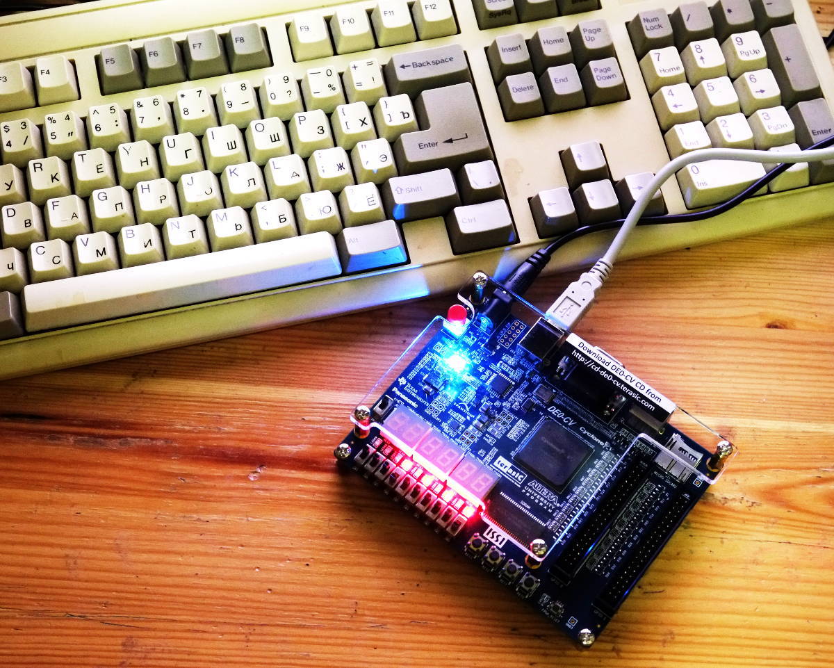
One of the directions of my activity is teaching in a circle of robotics in a small town in Belarus. Having plunged into this whole kitchen and participated in various competitions not only as a team coach, but also as a judge, I came to the conclusion that arduino in particular and microcontrollers in general are not the best base for competitive robots (I’m silent about that). Many tasks are more efficiently solved at the bare electronics level. In addition, 90% of the circles and "schools" of robotics do not even give basic knowledge of electronics, focusing purely on "learning" the programming of finished designs. But purely electronic robots (for example, undeservedly forgotten BEAMs) are tailored for a specific task and changing the conditions of the competition will lead to the need for a substantial overhaul of the robot, which is not always possible. Here I remembered about programmable logic. YuriPanchul . I take this opportunity to publicly express my gratitude to him. Thanks to him, our club received the TerasIC DE0-CV board with Altera Cyclone V on board for free.
Actually this and subsequent publications will constitute real educational material, which we implement at the circle. And I will be grateful for the constructive criticism and comments, since the use of FPGAs on mugs for schoolchildren is an area that is not yet popular.
So here we go. This publication will describe the first steps in Quartus, a description of elementary digital logic in Verilog, and loading the configuration into Altera Cyclone V. FPGA. We will work with the TerasIC DE0-CV board, which has an integrated USB-Blaster on board. We also touch upon the issue of “launching" USB-Blaster under Linux.
Launch Quartus:
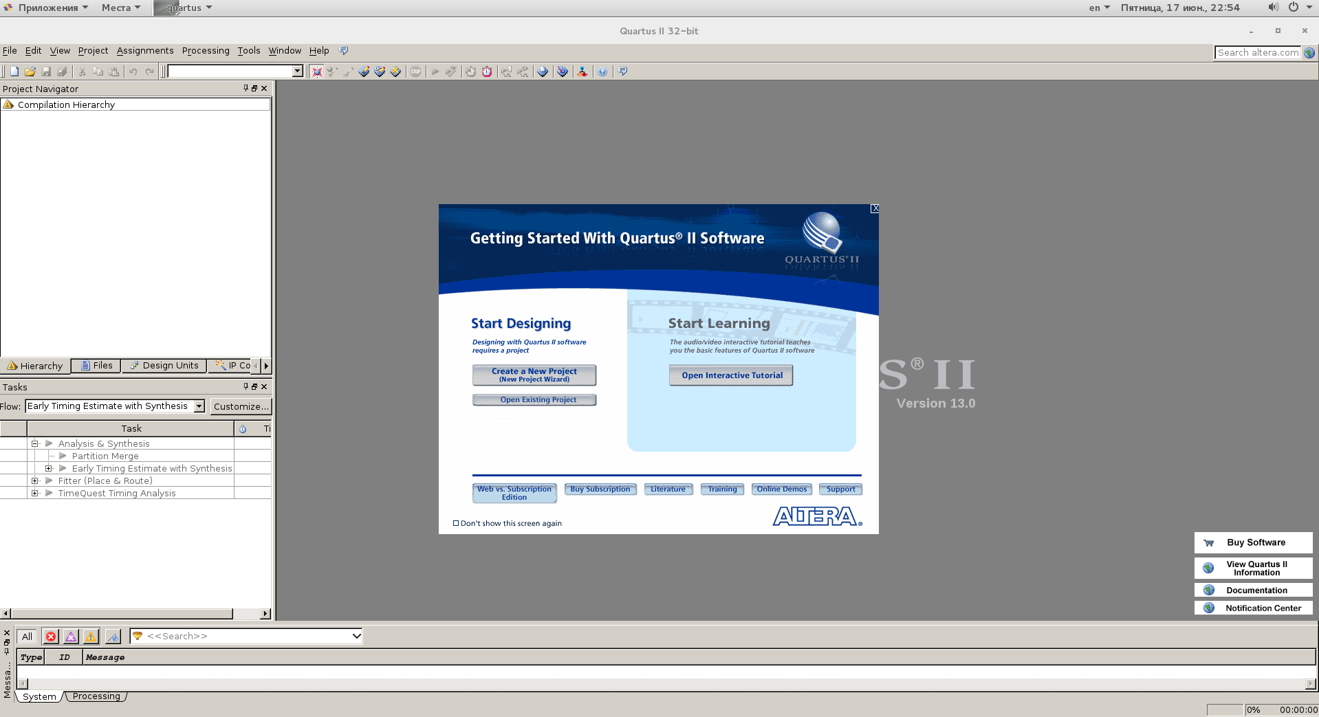
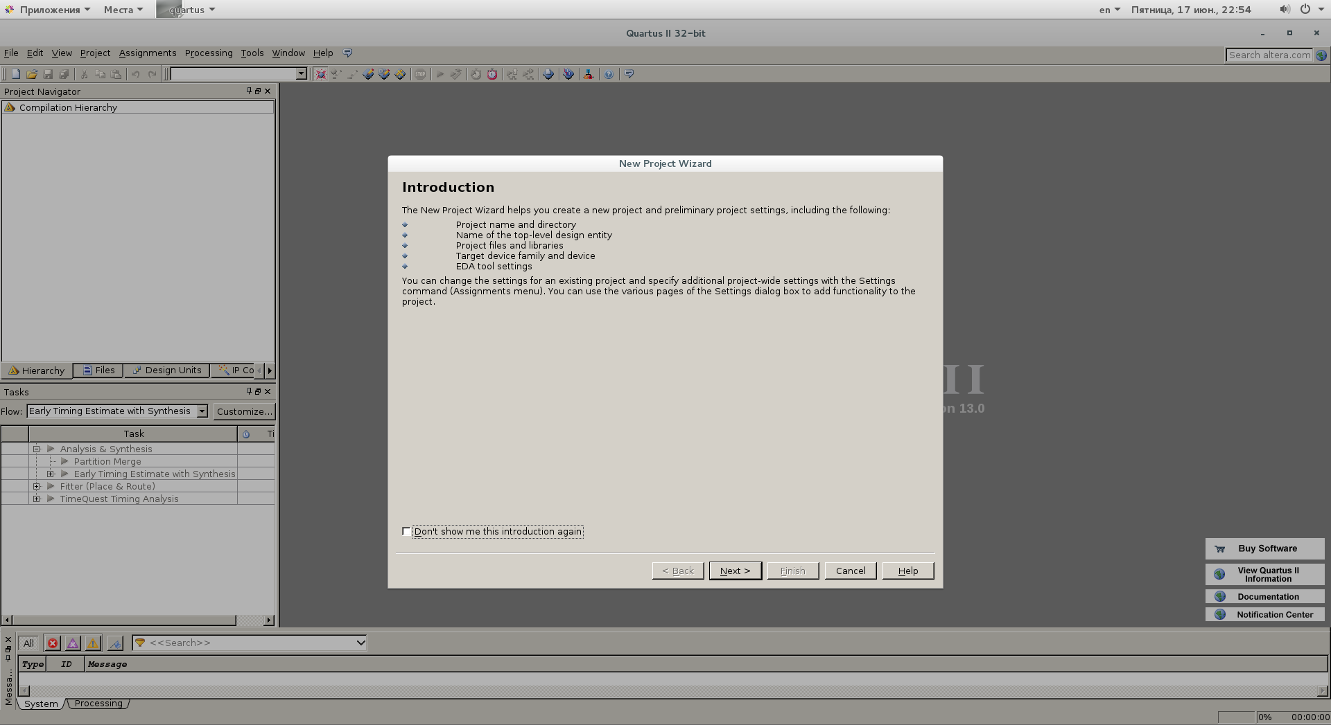
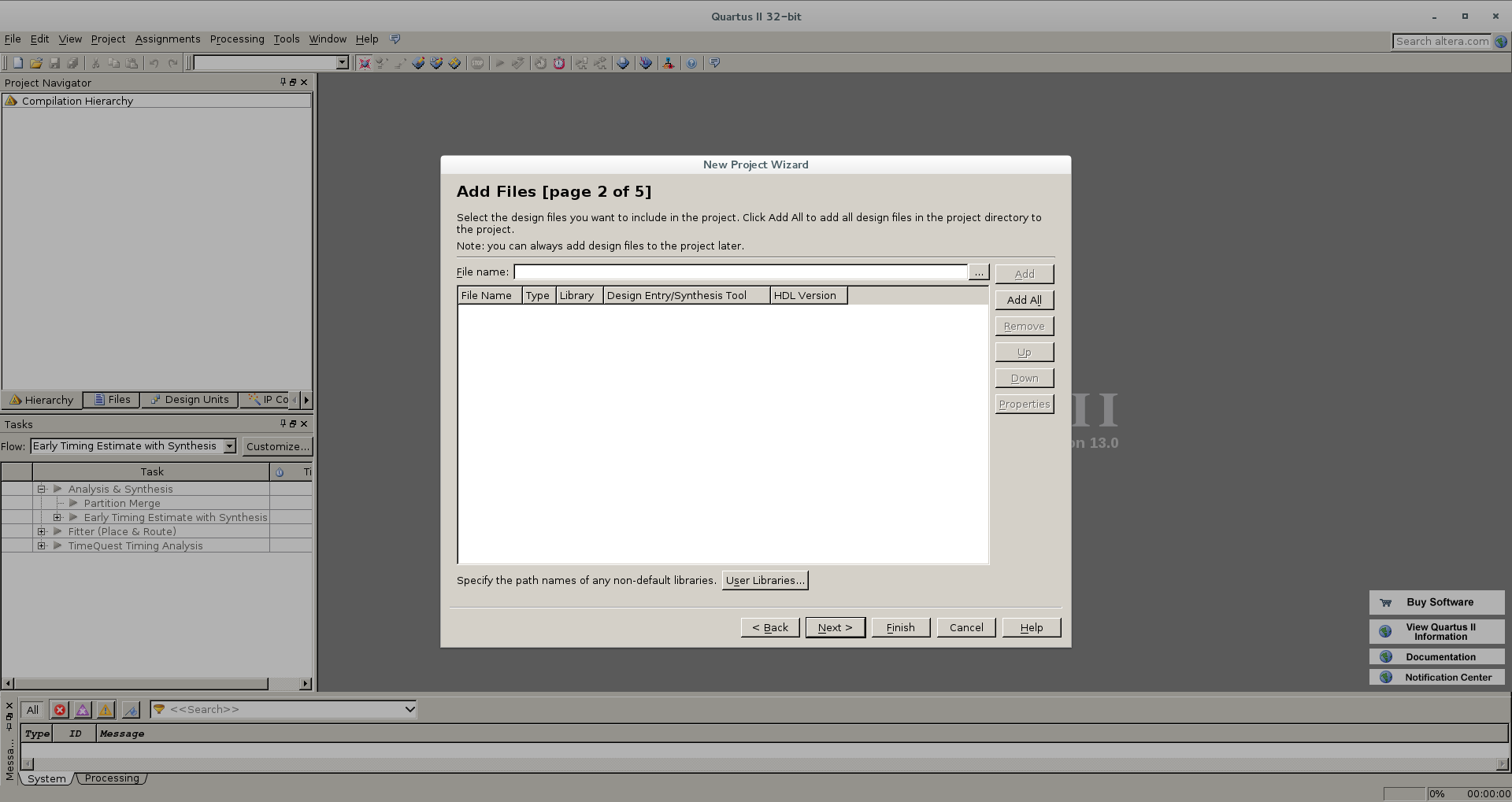
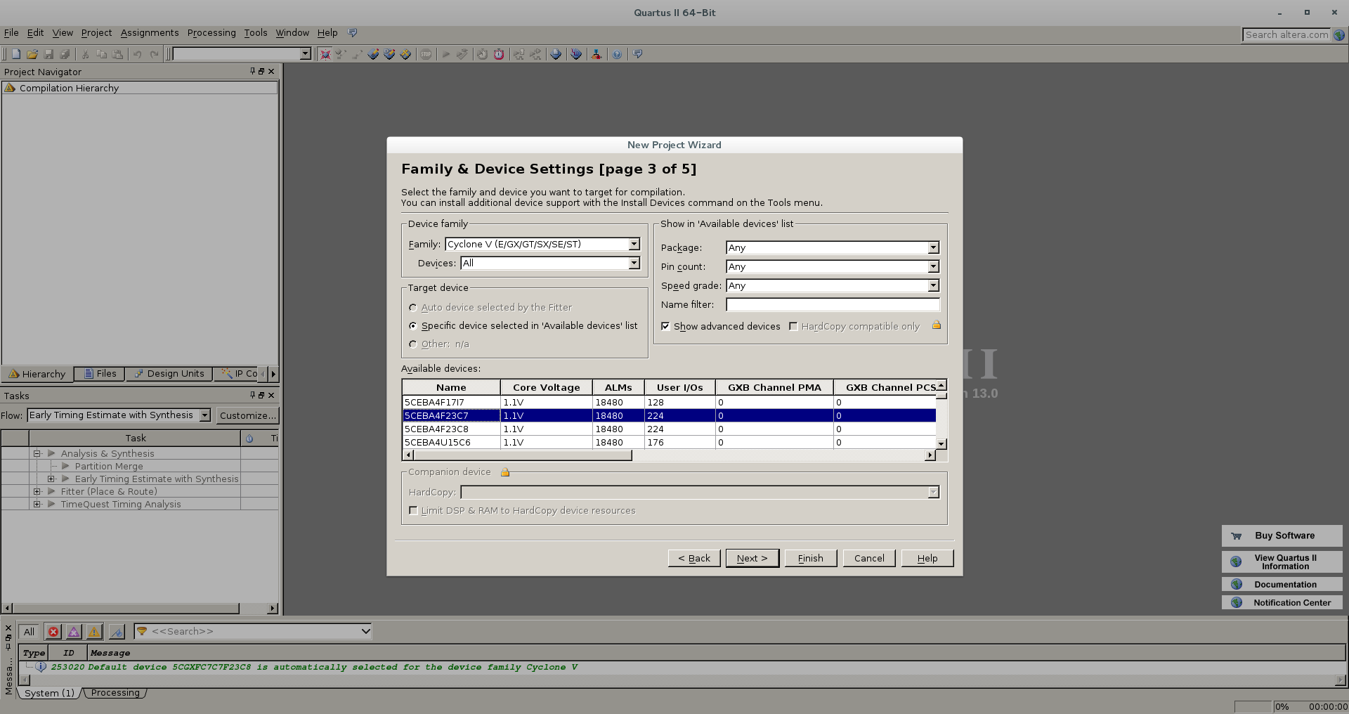
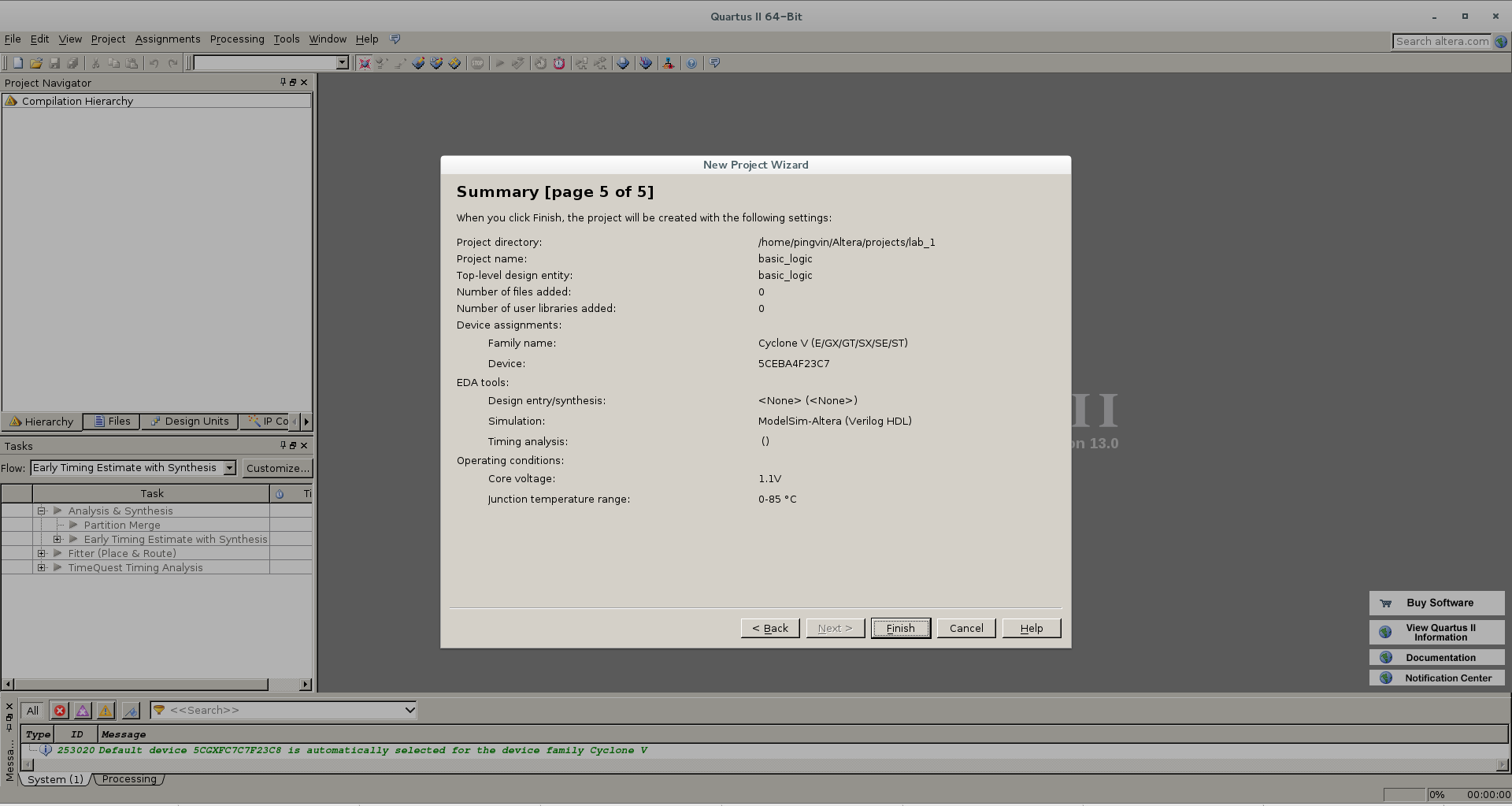
Select "Create a New Project". The dialog box of the project creation wizard starts. Then just click Next. And now we need to choose the working directory for the project (do not forget about access rights!). We come up with the name of the project: At the next step, we are offered to add additional files to the project. At this stage, we do not need this, but in the future, to facilitate the work, it is worth adding at least a pin destination file. Now is the time for important settings. At this step, we need to choose the crystal under which the project is written. In principle, if you make a mistake or want to recompile the project for another device - this can be fixed later. Here we are offered to choose additional tools. We leave everything as it is and click Next.


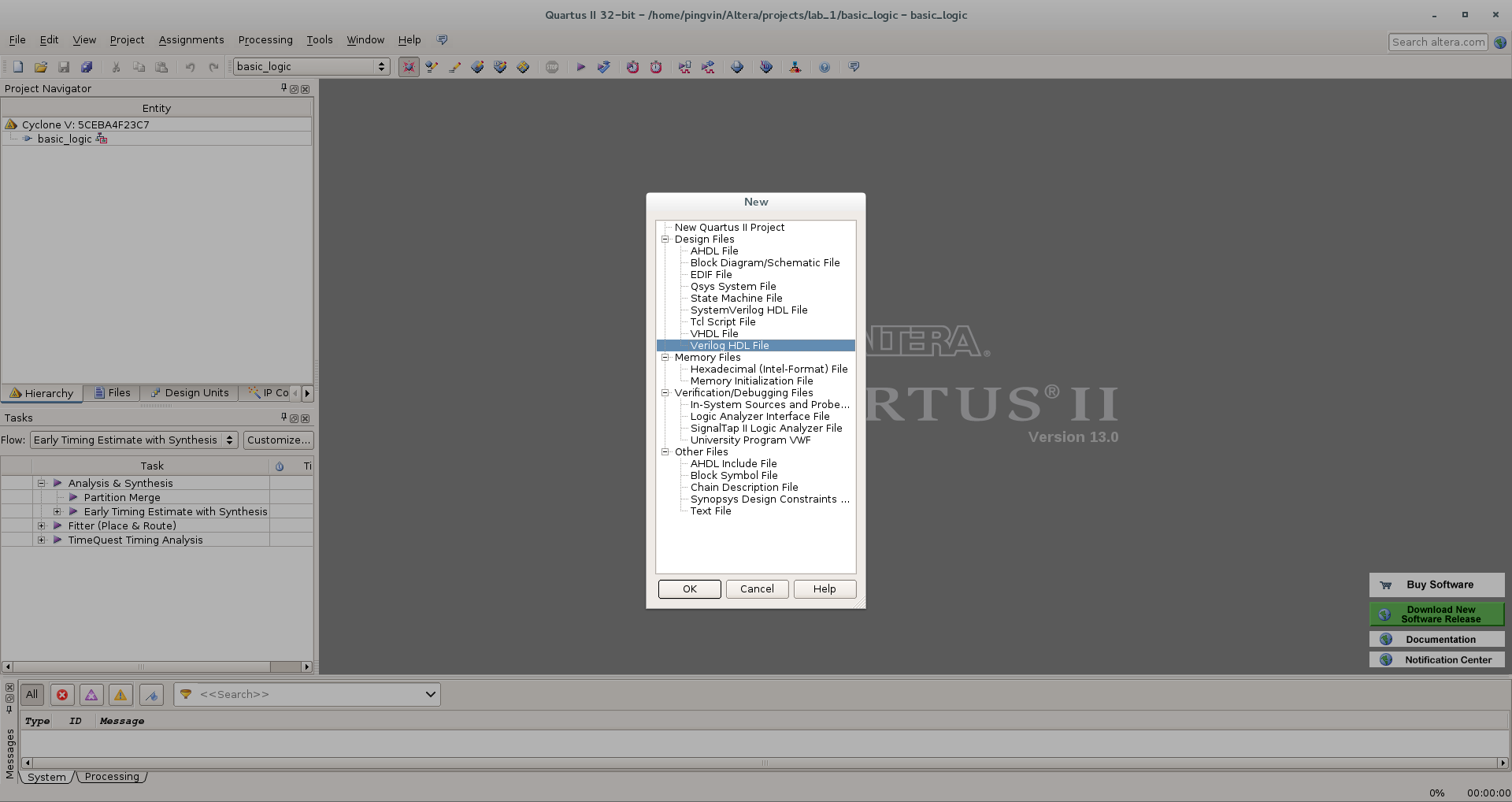
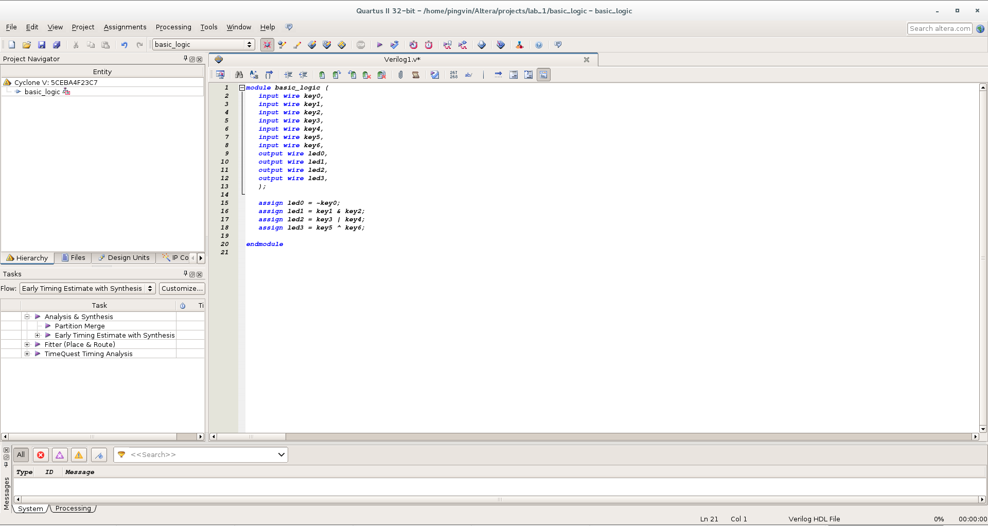
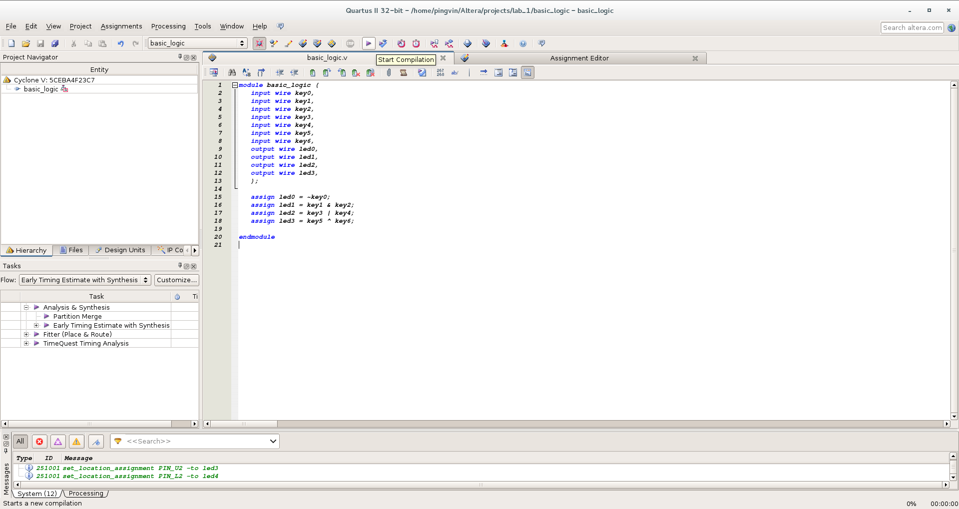
Well, we completed the initial settings and created the project. Click Finish. Now we need to create a file that describes the logic of the project. Go to the File / New menu , a dialog appears in which you want to select the file type. In principle, the logic can be drawn in a special graphics editor, but now we select Verilog HDL File: The file is created, we write the text of our program that describes the elements NO, AND, OR, XOR
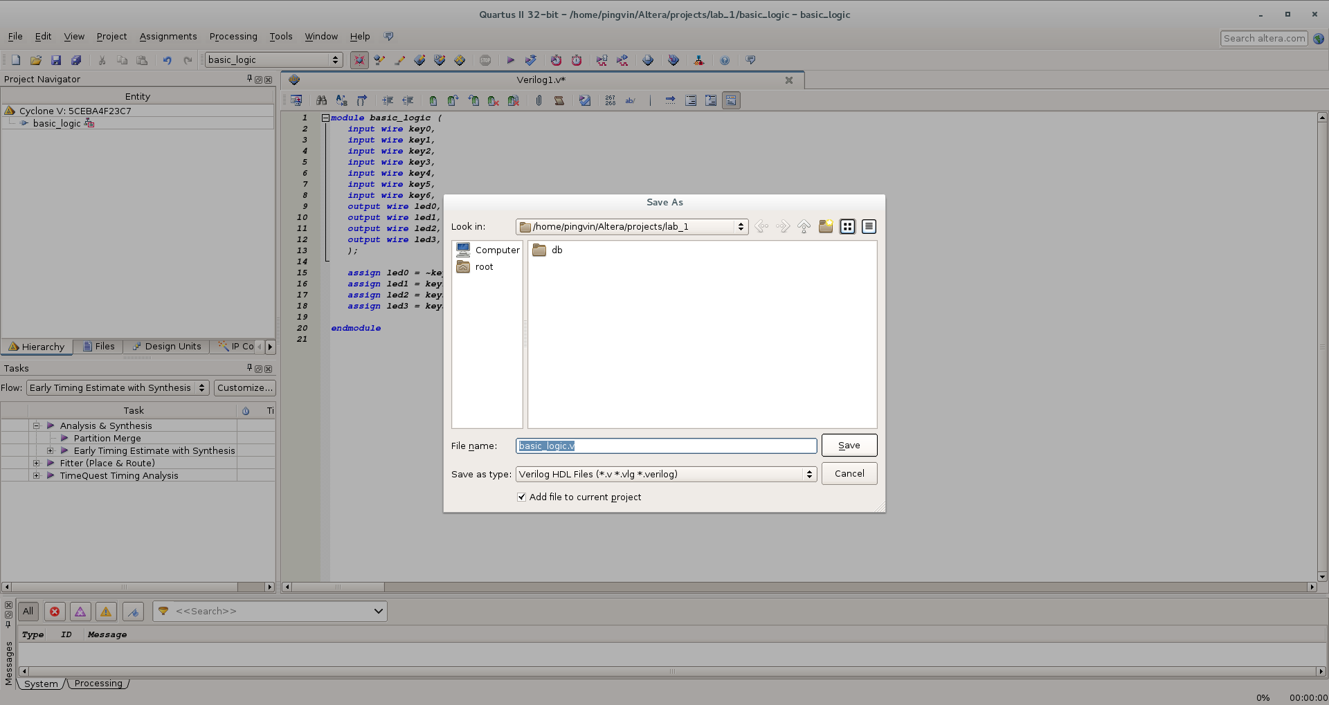
. As inputs, we use the switches on the board (key *), and the output status is indicated by LEDs (led *). A small remark: the board manufacturer suggests creating a configuration file for inputs and outputs in a special program that works only under Windows. If you go this way, you need to make sure that the names of the "wires" and "registers" in the program match those in the configuration file. But now we will do everything manually, so we are free to choose any names. Now save the file. An important point - for correct operation, it is necessary that the file name matches the name of the module described in the program (In our example, basic_logic ).
Now you need to make a number of settings to successfully compile the project. First, we indicate which module we have in the main explicitly. Specifically, this project is not relevant, but for complex projects with many modules, this step is required. Go to the Project / Set As Top Level Entity menu . Done. Next, you need to make a number of settings for a specific crystal. Select the menu item Assignments / Device . A dialog opens in which we have the opportunity to change the type of crystal (or check that we specified it correctly earlier): Now click on the Device and Pin Option button
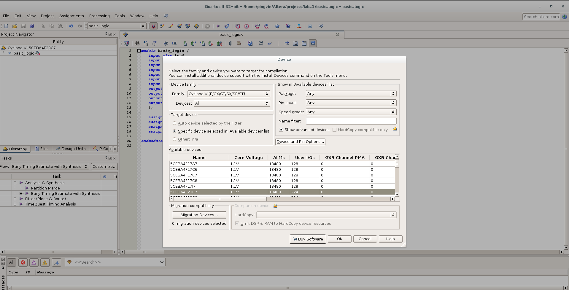
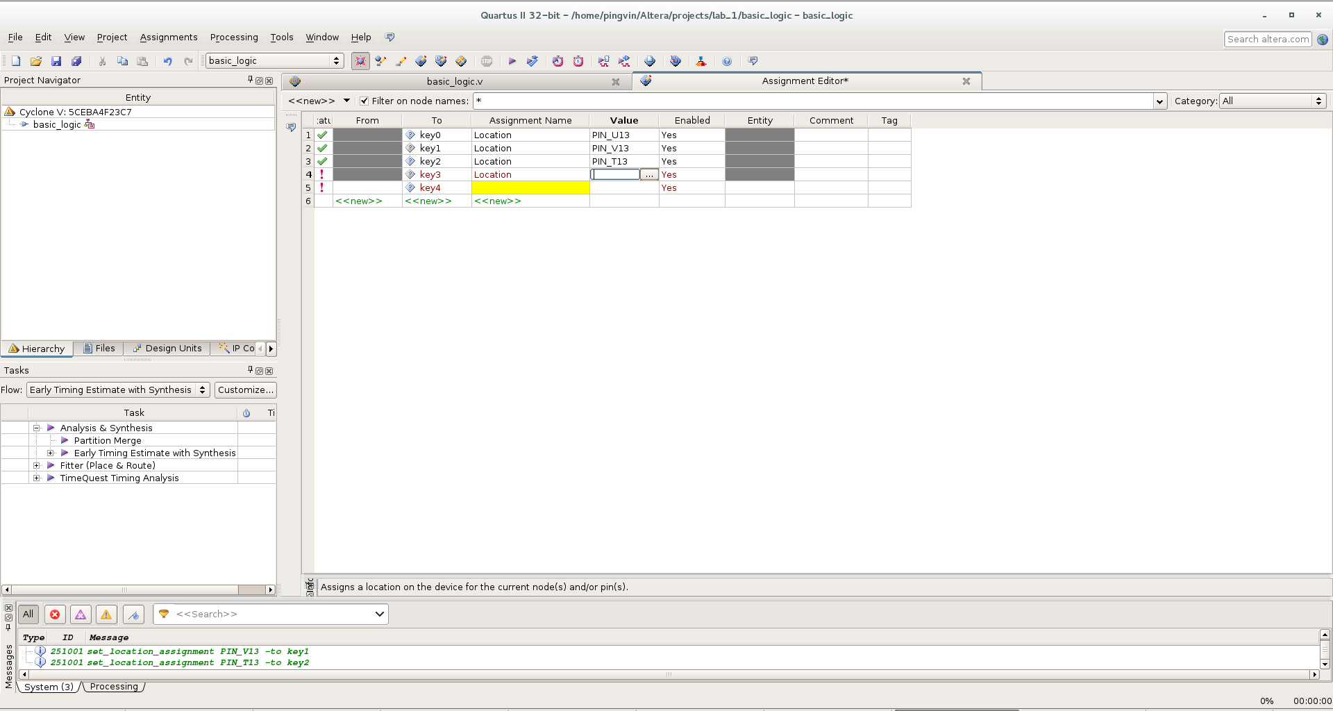
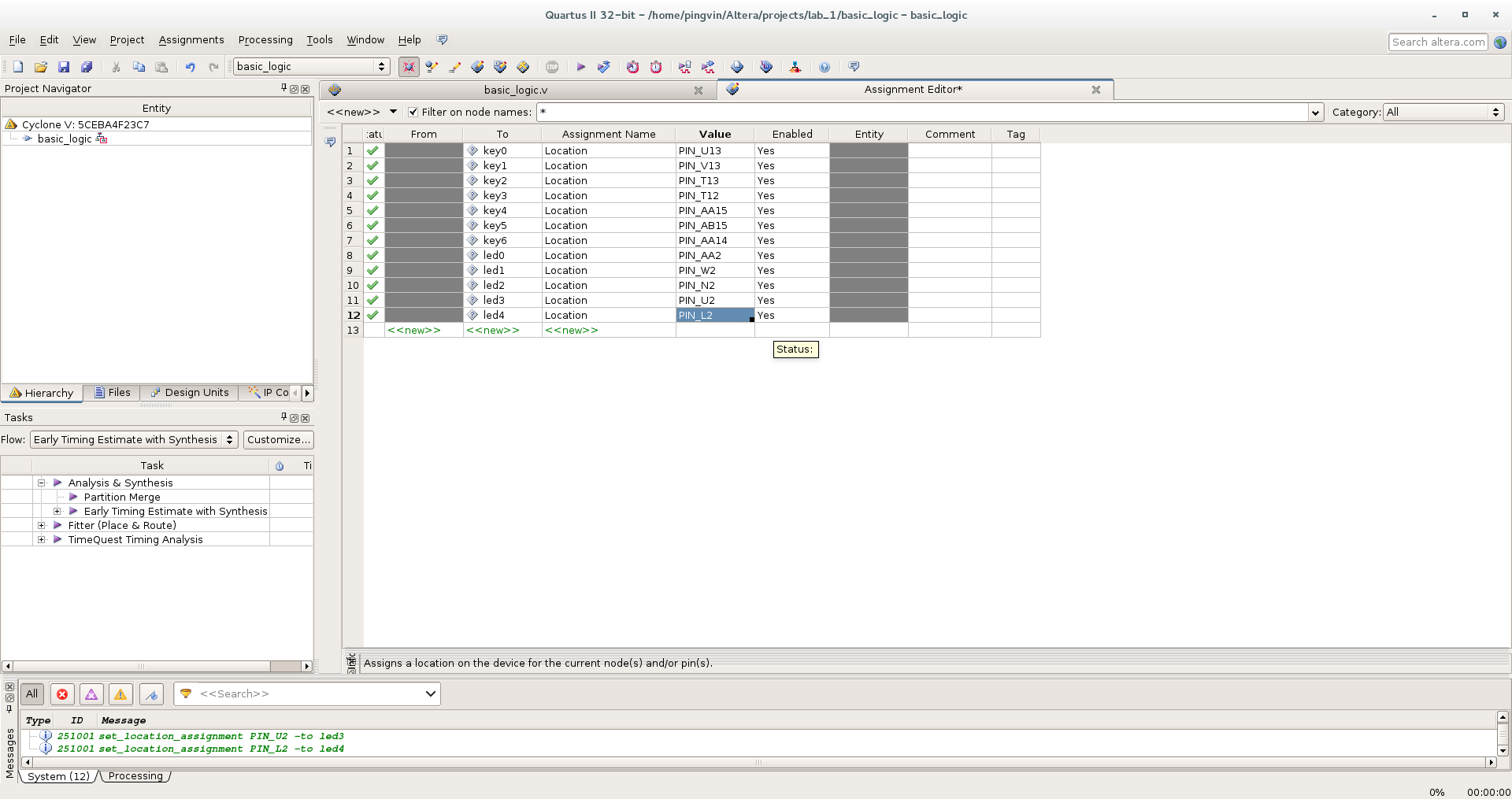
and in the dialog that opens, first of all, set the state for unused conclusions. By default, all unused contacts of the chip are connected to zero power. But we do not know how these conclusions are physically separated on the board, and such a configuration can lead to a short circuit and failure of the chip. Therefore, it is safer to make unused pins as inputs with high resistance - As input tri-stated The next necessary step is to indicate which physical legs of the microcircuit correspond to the inputs and outputs of the module described by us. To do this, go to the Assignments / Assignment Editor menu . In the window that opens, we make the necessary appointments according to the scheme of our board. In the column To enter the name of the input or output. In the Assignment Name column
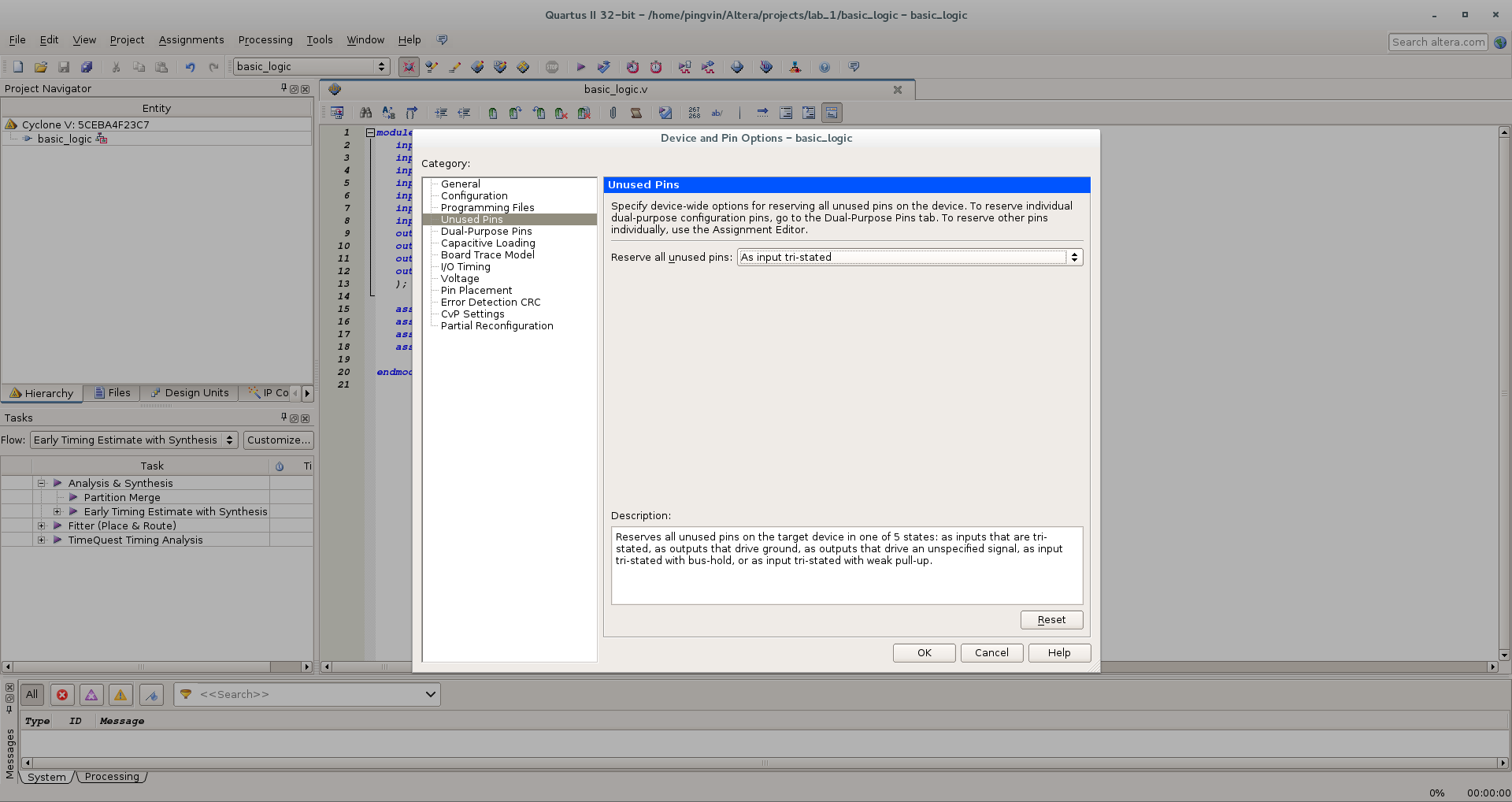
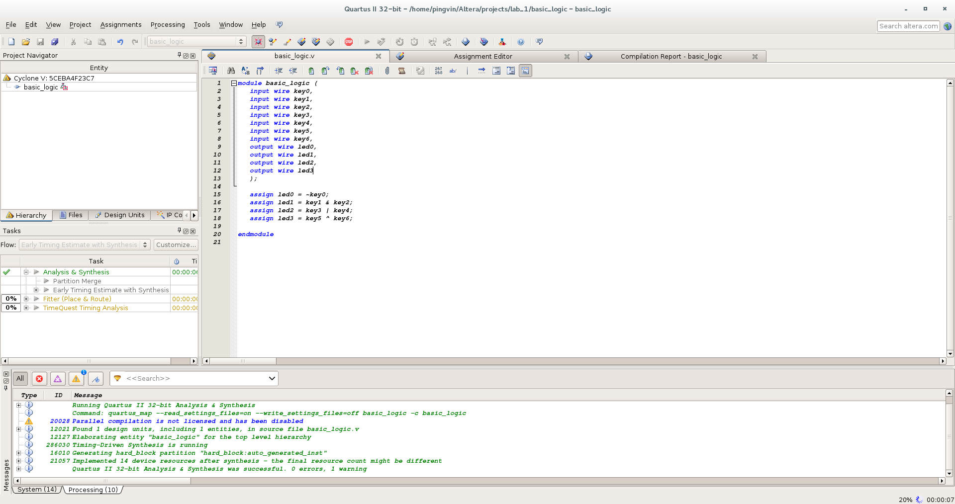
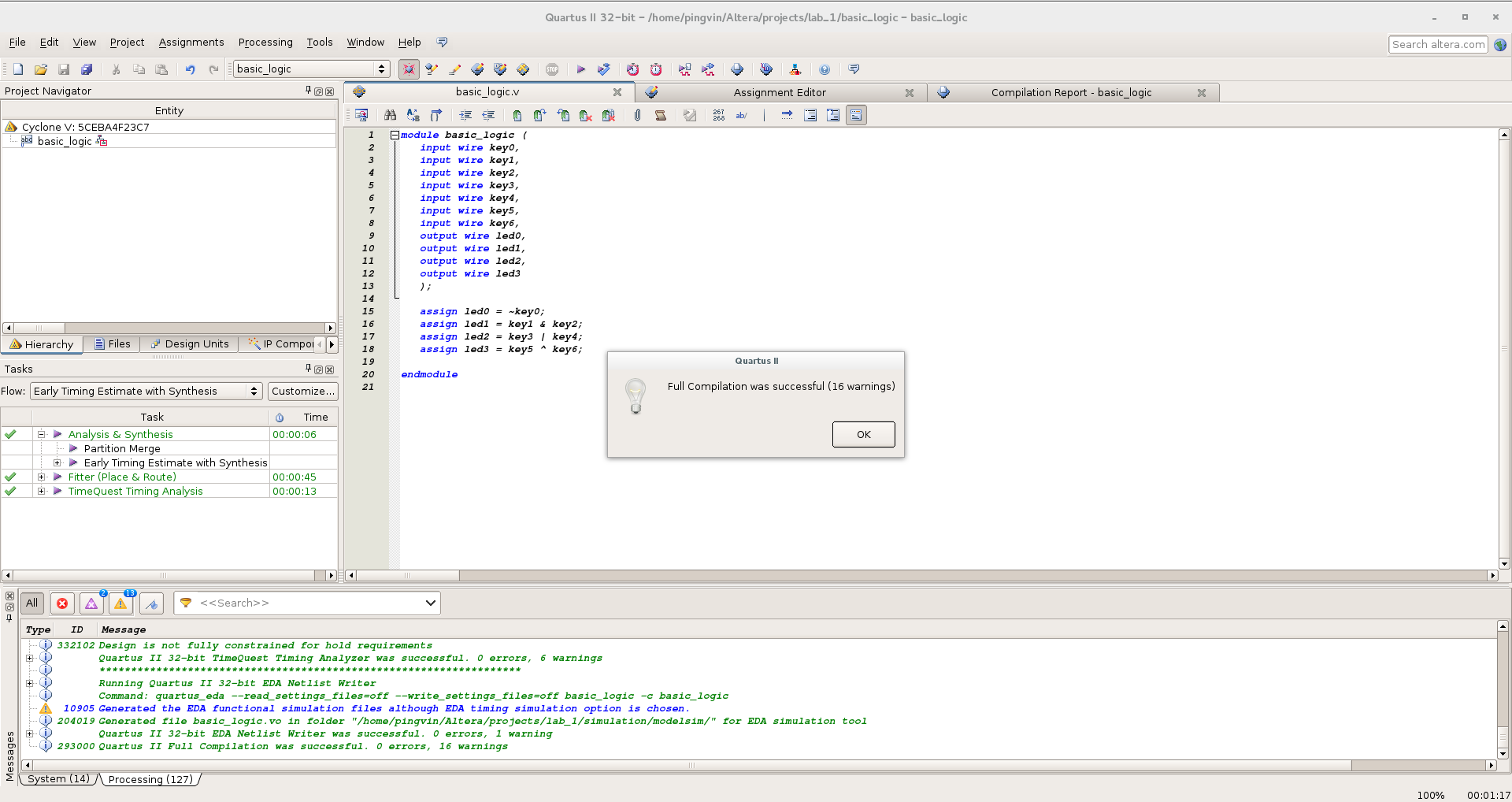
select the Location setting we need from the list . In the Value column, enter the name of the contact of the microcircuit: A logical question: where does the name of the contacts come from? Usually in a datasheet on a board or a specific chip there is a PIN OUT sign. Just as I wrote earlier, a special program that creates a configuration file can go with the board. And now you can take advantage of these data: Finally, you can click the Start Compilation button! We get 16 warnings. Nothing serious. You can see the report: Now we connect the board and run the programmer program: Tools / Programmer.

Linux automatically picks up USB-Blaster, but the firmware does not work ... Well, open your favorite console, arm yourself with a tambourine and plunge into the documentation for Quartus ...
First, make sure that the system sees the programmer:
dmesg | tail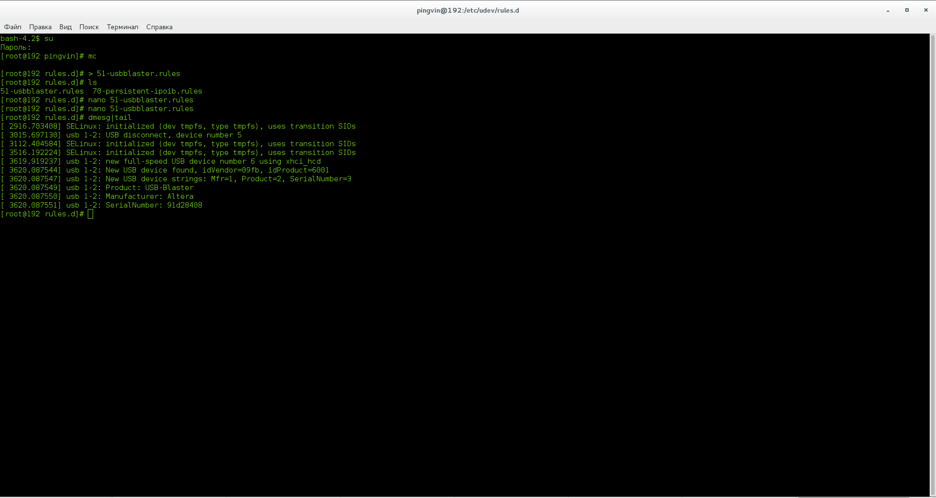
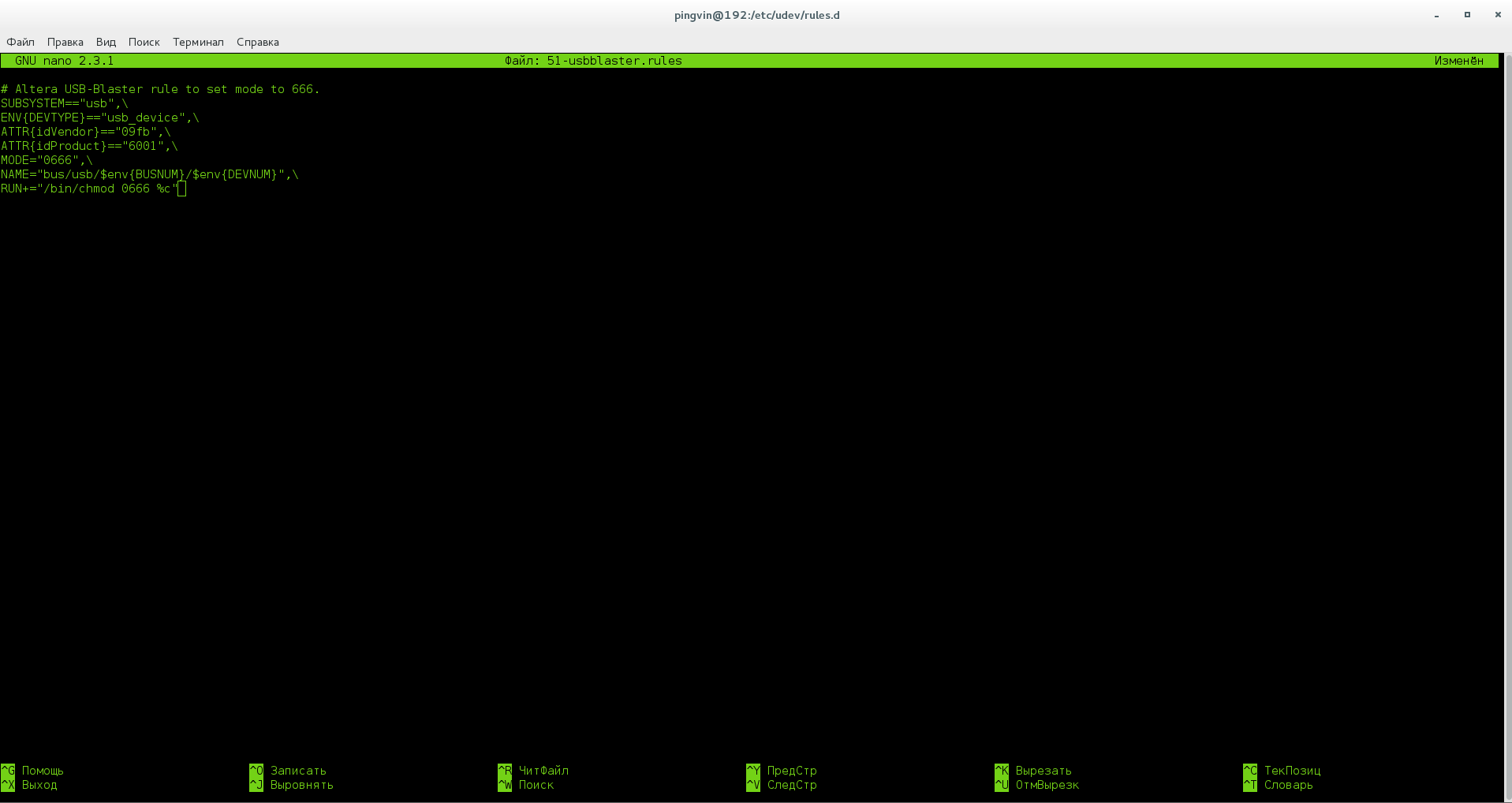
We go to the /etc/profile.d/ folder , where we create the custom.sh file , and then in the /etc/udev/rules.d/ folder a file called 51-usbblaster.rules and fill it with meaning: Now everything works and the firmware loads fine to the chip: We admire the result, play with the switches, blinking LEDs: