Weekend repair or how to fix Saitek Rhino X55 / X56 throttl controller
A little adventure of two joysticks. The story of how to fix the Rhino Throttle Controller X55 (X56) with minimal cost. Read with caution! Contains an unacceptable attitude to the circuitry and the rules of switching electronic devices.
Disclaimer! To do this as I did wrong, in a good way, it is necessary to do a replacement of the component or at least put TVS diodes on!
I have two joysticks - a set of Rhino X55 (X56) and both of them had Throttle Controller flying. The first one took off almost a year after the purchase, and so the second appeared - they sent a new, more recent X56 model under warranty. But the happiness was not long, his trottle controller also ceased to be determined after a while.
We abandoned him, because there was no time to fiddle with a guarantee, and the second half - the joystick itself worked fine.
And then, a week ago, my son was concerned to replace this one under warranty, because Saitek moved to Logitech, why not try it?
But it did not, the warranty period has expired and the second joystick.
Well, once I went so drunk, I have nothing more to lose, and I uncovered an oscilloscope.
The method is simple: we poke the oscilloscope in all places and see what happens.
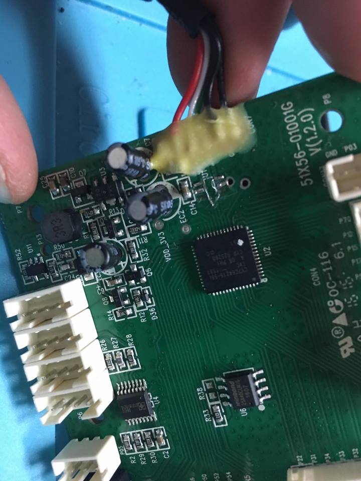
First of all, I found out that the controller does not access the SPI FLSAH (W25X40L) stand-alone chip, and it should read the USB device identifier from there. In addition, I looked at the working joystick and there it turned out to be exactly the same chip of the controller CY7C64215-56LTXC and in general it was clear what and how it should work.
It became more interesting when I noticed that the working joystick chip is powered by 5V via DC-DC up / down converter from 5V included with USB. Well, it became clear that they stabilize the power supply, but at the output of 5V. But the “fire victims” were fed 3.3V through a lowering stabilizer. While the power supply chip is universal and can work within 3.3V - 5.2V. "Hmmm" I thought, maybe he has little power? But the filing of 5B did not help.
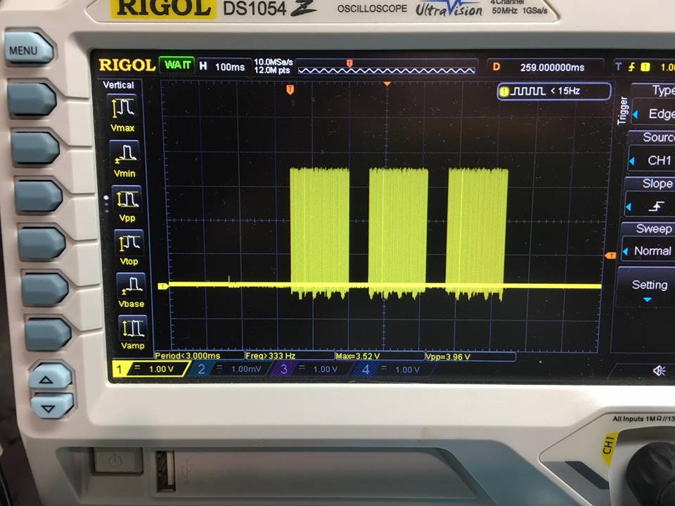
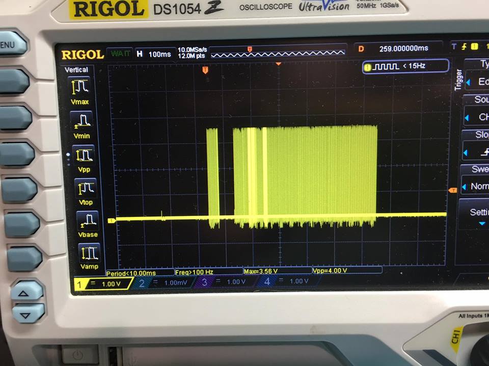
The second difference was in a small buffer chip that transferred data signals from USB 5V to 3.3V level. And when I compared the signals at the controller inputs, I saw that the signals from the computer are in insufficient levels (see the pictures).
Actually repair.
Well, taking into account that in the joystick running on 5V, the YUSB data signals go directly to the controller and there are only shunt diodes standing there, I uprooted this level converter and started the USB data lines directly to the controller. And a miracle happened! It worked!
So now I have two working sets of the Rhino X55 and Rhino X56 joysticks.
Pictures with captions - an explanation.
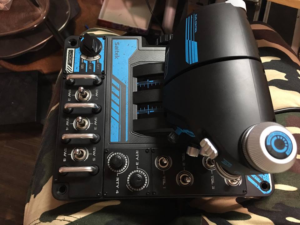
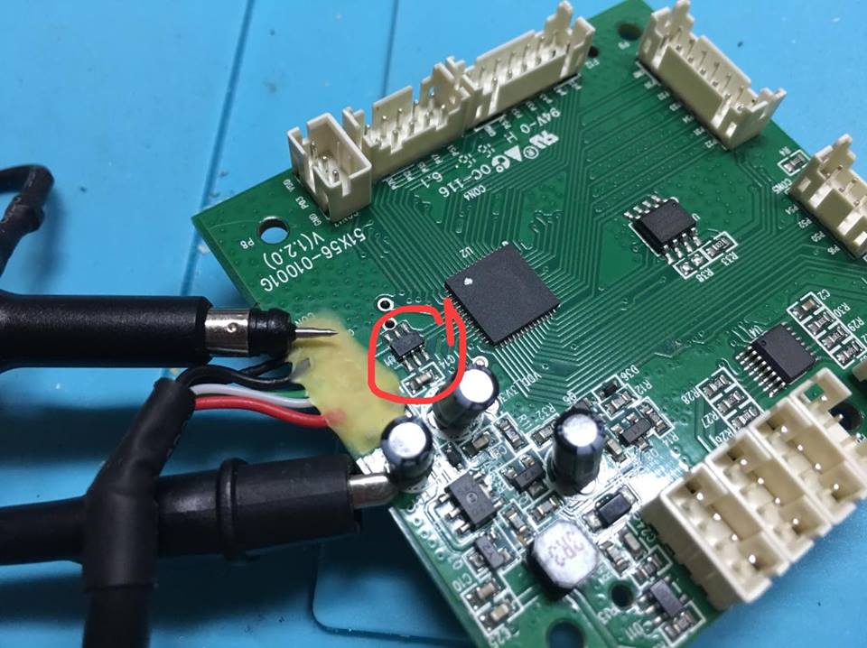
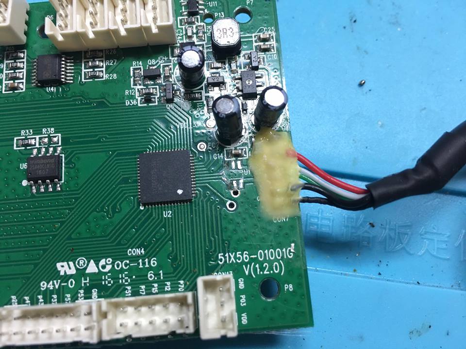
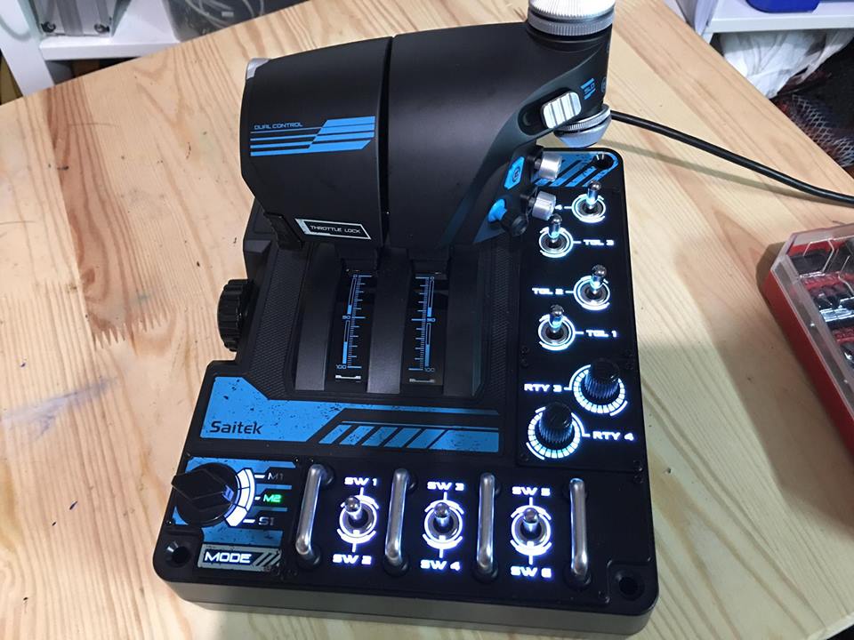
This is a patient before surgery.
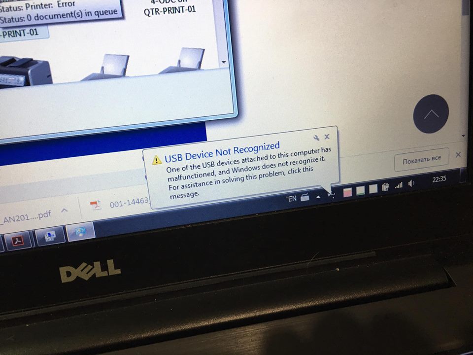
So it "does not work"
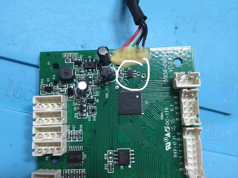
It is circled in a vicious buffer. Below it is the chip CY7C64215-56LTXC, and even lower SPI FLASH W25X40L
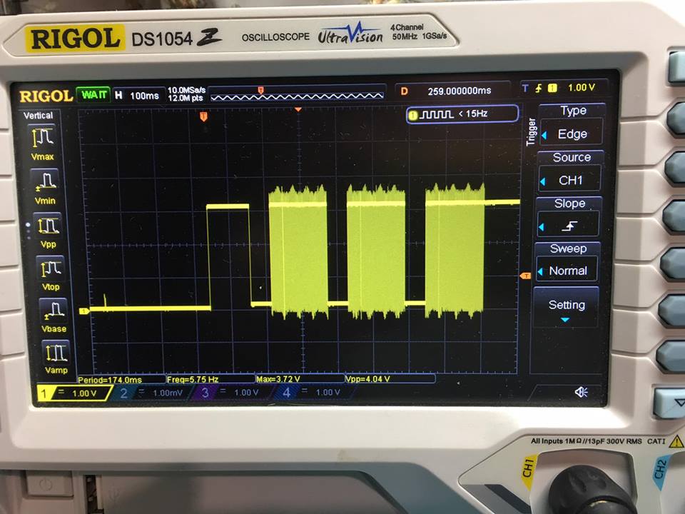
This is a USB signal from the computer to the buffer. Notice the level: 3.5V
This is also a signal from the computer but this is output from the buffer to the computer
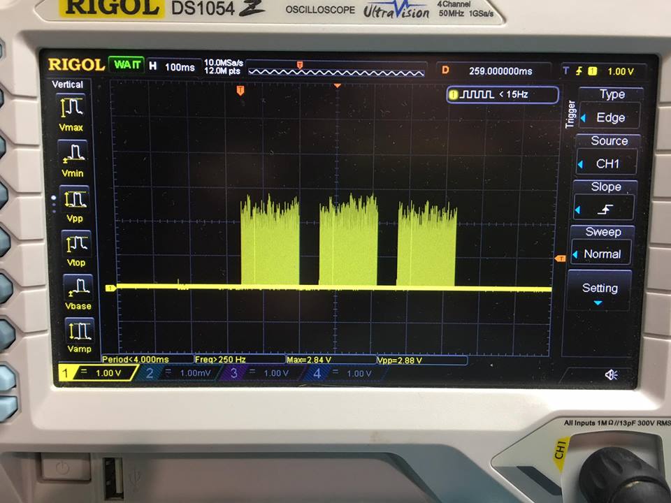
“Here he is! A bad tooth! ”(C) is a signal after the buffer from the controller. As can be seen from the level, it barely reaches 2.5V, so the controller does not recognize logical ones ...
This is the signal from the controller (output) to the buffer. Also level remarkable
Here it is, this wicked buffer-transducer, preparing for amputation
Cockroaches extracted!
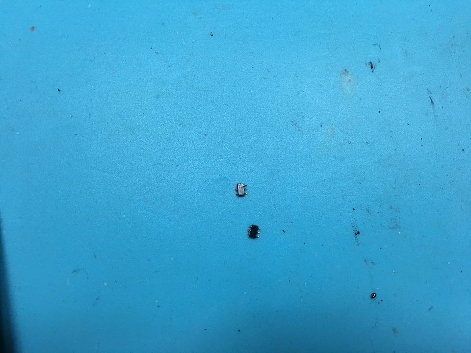
Unfortunately, it is very difficult to unsolder them - the paths are very gentle and have come off in some places. Well, it does not matter, such a trifle for me to solder is not the first time.
Done!
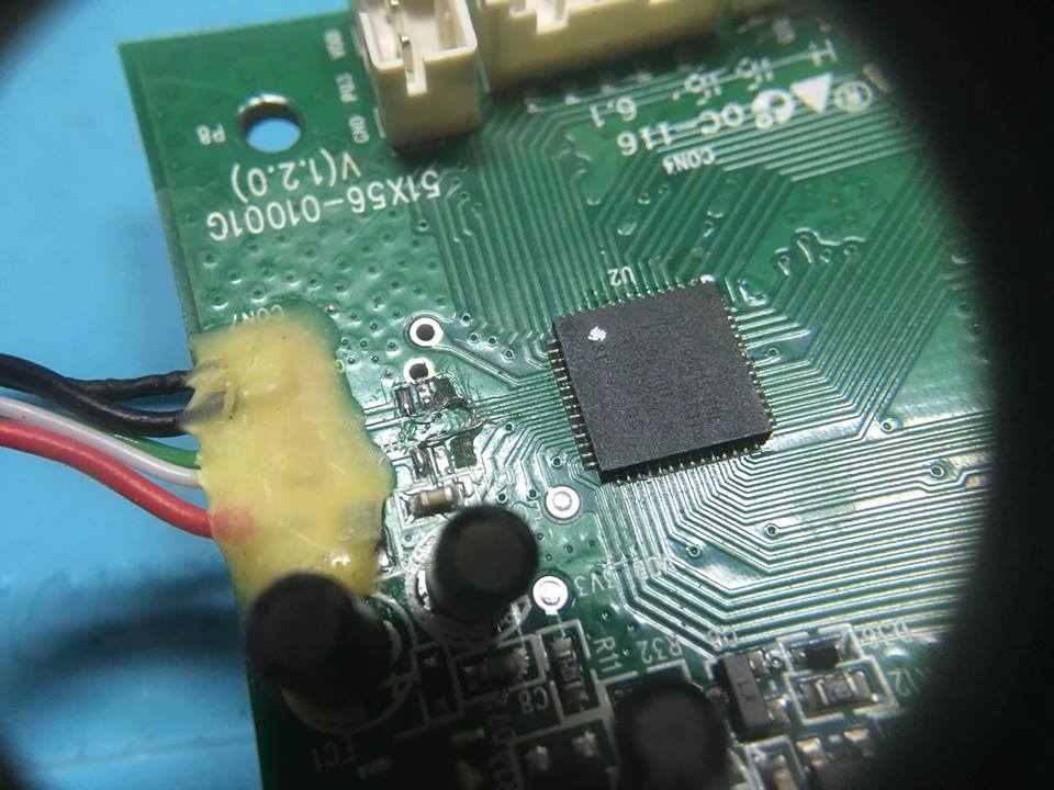
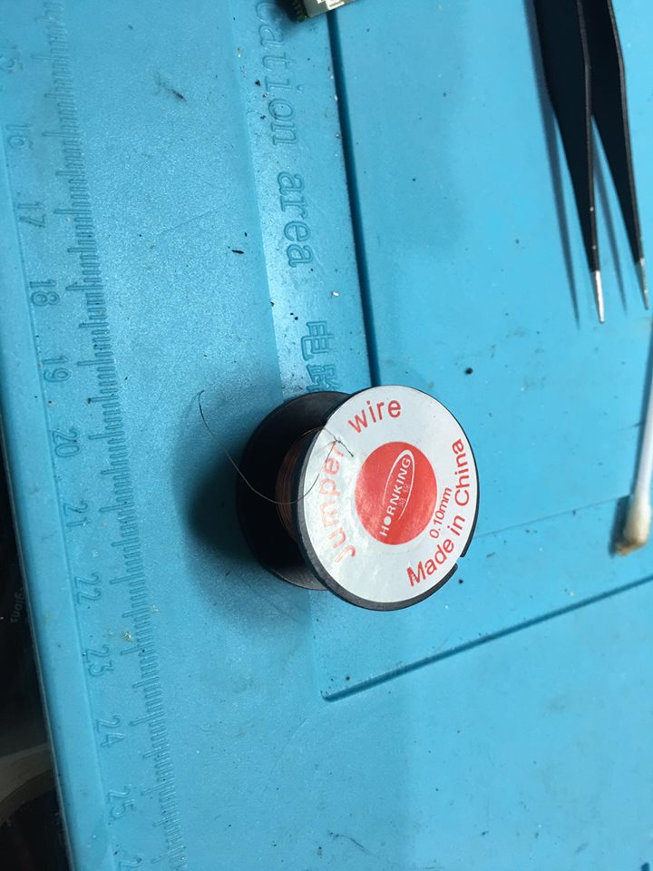
It is necessary now to pour something
This is what I connect the tracks
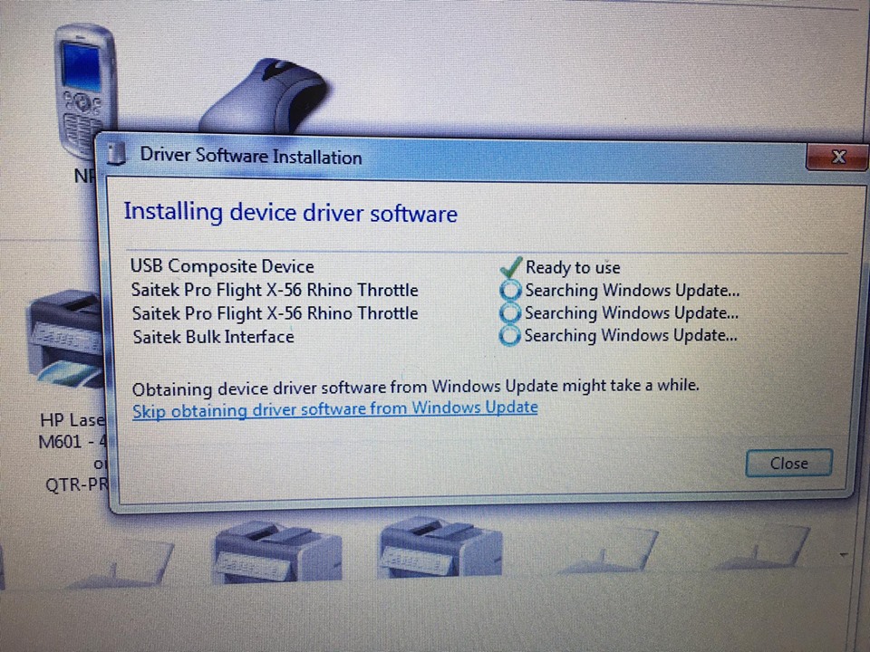
The result was not long in coming! Everything is determined now!
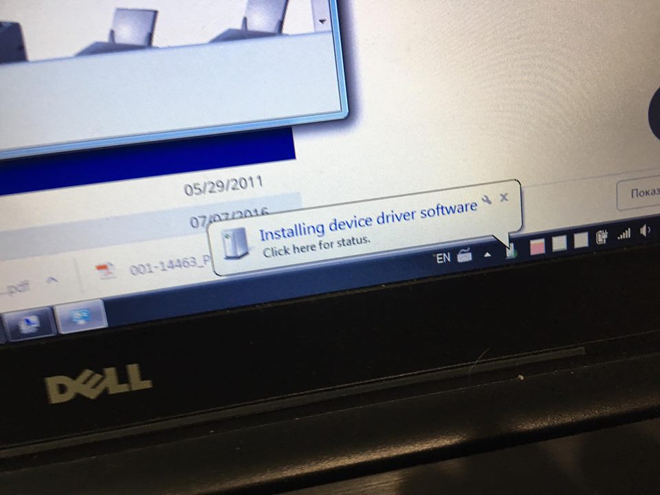
Drivers ...
These are signals without a buffer, as seen from the level they are the same as the controller gave without (before) a buffer
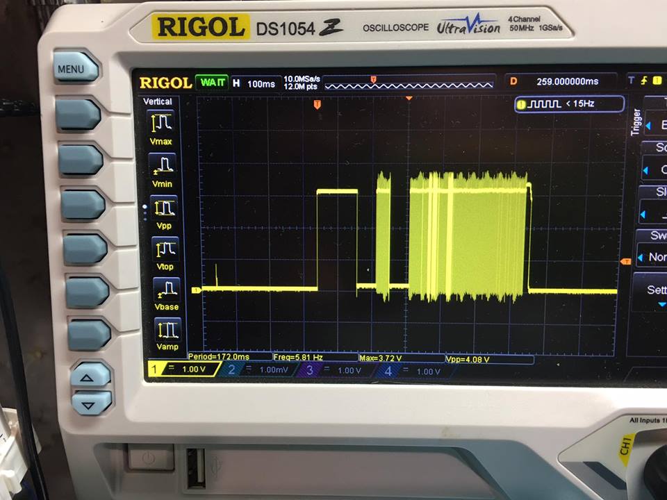
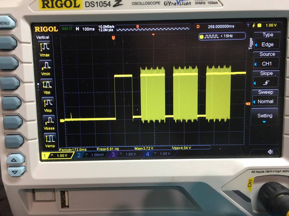
This is from the computer to the chip - you can see the level is quite sufficient now.
Lit up! :)
Well, that's it. The plans still put protection on these lines.
Update:
In comments, rstepanov suggested that the remote cockroach is IP4234CZ6:
IP4234CZ6
I will put it back when it arrives.