The EFM32ZG110F32 microcontroller article
It just so happened that we had quite a few EFM32ZG110F32 microcontrollers in our warehouse, this is the Zero Gecko series from SiLabs. The controllers are cool, but not yet very popular, that's why I am writing this article.
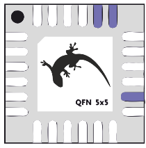
As an advertisement, we offer this kit: ARM Cortex-M0 +, 32 Kbytes Flash, 4 Kbytes of RAM, DMA, I2C, UART, USART, 12-bit ADC, current DAC, comparator, hardware pulse counter, real-time clock and various things to reduce power consumption in the QFN-24 package for $ 0.96 .
upd: yes, you can piece by piece
Under the cut is a long post with a detailed overview of the chip and the debug board, a description of the available programming and debugging tools. Examples of working with various peripheral blocks of the chip are given, proprietary development tools and the mbed platform from ARM are used.
EFM32 is a 32-bit memory-consuming microcontrollers based on ARM Cortex-M processor cores. Their main feature is the support of a variety of software and hardware technologies to optimize energy consumption, but along with this, a standard set of peripheral devices is also provided.
The hero of this article - the EFM32ZG110F32 microcontroller - belongs to the youngest series of the EFM32 family, it is called EFM32 Zero Gecko. These are the simplest and cheapest controllers under the EFM32 brand, they are built on the basis of the Cortex-M0 + core and differ among themselves in the set of supported peripheral devices and cases. What EFM32ZG110F32 represents is the easiest way to judge by such a scheme.

The color for each block indicates the power consumption mode, up to which the block can be used:
To evaluate the described microcontroller, it is most convenient to use a debug board and in this article the capabilities of the crystal will be demonstrated precisely with its help. The kit for EFM32 Zero Gecko series microcontrollers is called the EFM32ZG-STK3200 and is purchased for $ 42, please contact. The kit consists of a USB cable, a battery, and such a board.

Here it is important to note this: the article is devoted to the EFM32ZG110F32 microcircuit, and on the debug board there is a more “older” microcontroller of the same series - EFM32ZG222F32. The first controller is made in the QFN-24 package, the second - in the QPF-48. As a result, only 17 I / O lines are available on the EFM32ZG110F32, of which up to five can be used as ADC channels, and on the EFM32ZG222F32 there are already 37 lines, of which only two potential channels for the ADC. The rest of the crystals are completely identical, so the examples discussed below can be safely attributed to both EFM32ZG222F32 and EFM32ZG110F32.
Now back to the debug board and consider the modules available on it:
If your application is designed for a task in which power consumption is important, then the EFM32ZG-STK3200 will be completely useful to you (primarily because of the mentioned Advanced Energy Monitor measuring module). If the EFM32 will not be used in the device with battery power, and for some reason you do not want to use this board at all, then still keep a link to the Zero Gecko Starter Kit Schematics. It may come in handy when designing.
From the review of the microcontroller and the debug board, let's move on to the overview of the available software development tools.
For development, you can use either software from Silicon Labs or commonly used gcc or Keil, IAR, etc.
The platform from Silicon Labs is called Simplicity Studio. It includes an eclipse-based IDE, several utilities for developing and debugging a project, sample programs, all documentation and other components. It makes sense to use either only Simplicity Studio, or your usual development environment (Keil, IAR, Atollic, Rowley or Sourcery) or gcc along with utilities from Simplicity Studio.
Why is it worth downloading Simplicity Studio regardless of your preferred compiler and IDE?
Firstly, it costs nothing. Like any other software from microcontroller manufacturers, Simplicity Studio is a free environment. Secondly, distributions are available for Mac and Ubuntu. Thirdly, when you install Simplicity Studio for the selected family of microcontrollers (in our case, for 32-bit EFM32), you will immediately receive a complete set of development tools, documentation, and useful links that will be automatically updated. It's comfortable.
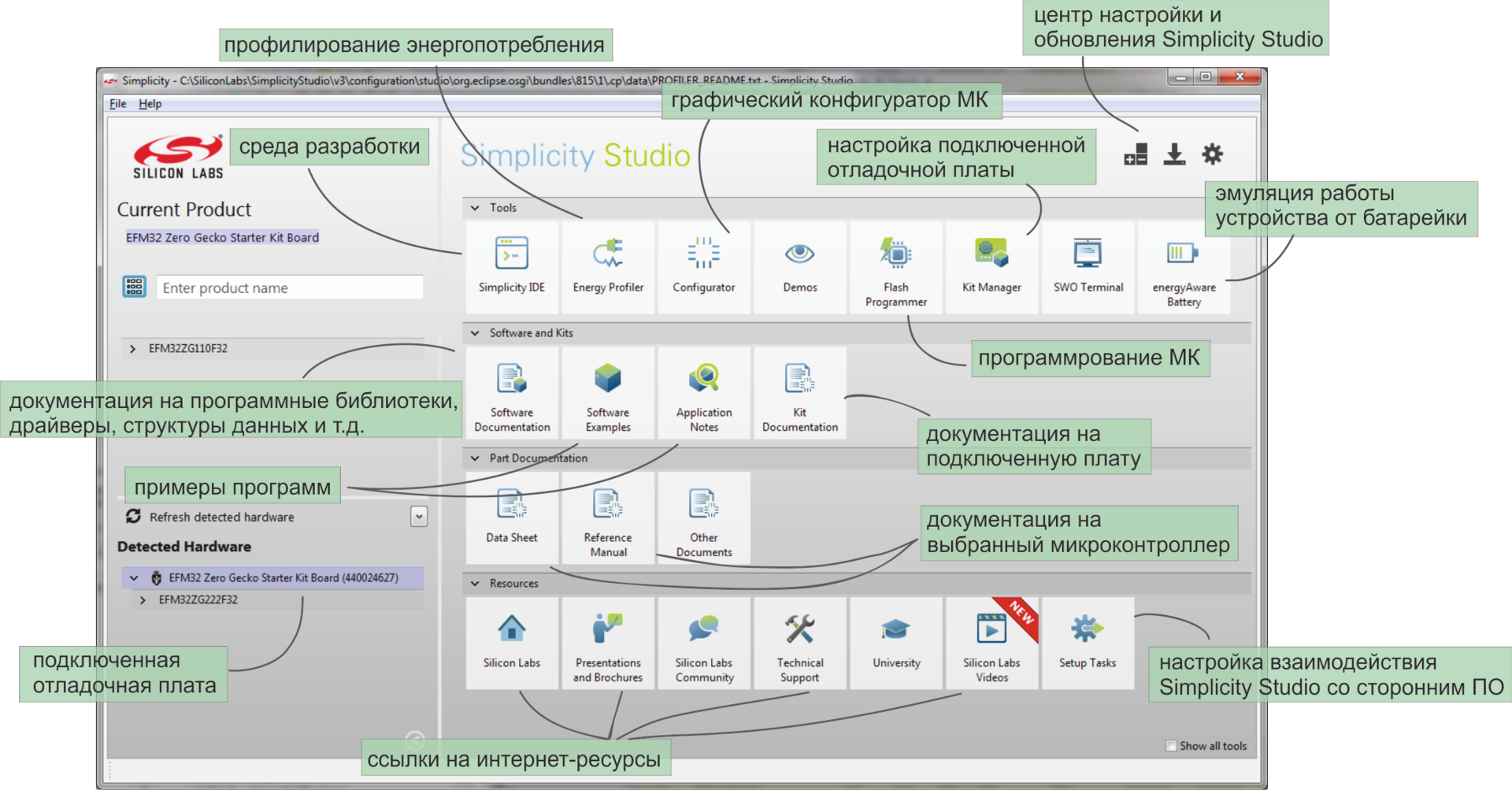
So, after installing Simplicity Studio and connecting the debug board (on which USB power should be selected), the main menu of the program appears.
All displayed tools are active specifically for the connected microcontroller. If, for example, a Zigbee module were selected, then a completely different set of icons would be obtained. The following options are available for debugging a program on the EFM32ZGxxx:
In the upper right corner is the update center, where you can check and download all available software and documentation updates for the selected series of microcontrollers.
Speaking of updates. The first Simplicity Studio, developed by energy micro, was magnificent in its simplicity. The next version was released at Silicon Labs. Simplicity Studio 2.0 had a much wider range of functions, contained an IDE and supported the C8051Fxxx microcontrollers, but it turned out to be very slow. By the current version (3.2), the situation has completely leveled off and working in Simplicity Studio is again very pleasant.
To introduce the reader to the capabilities of the EFM32ZG110F32 microcontroller, let us consider several examples of working with various development and debugging tools.
If the debug board appeared in your hands for the first time and you just started Simplicity Studio, then it makes sense to run a demo example and make sure that all this hardware and software complex is working fine.
After turning on the board in DBG mode, make sure that the board is detected (see the lower left corner of the main menu of Simplicity Studio). For the EFM32ZG-STK3200 board, in the front row, the Demo item will be available, containing ready-made firmware for the microcontroller.

You just need to select one of the projects and click the Finish button. The controller will be programmed with a finished binary file, the selected program will start on the board, and a graph of the current consumption level will appear on the computer screen.
If everything went well, then you can start developing your own programs.
All demos are also available as projects for each of the supported development environments. The corresponding files after installing Simplicity Studio are located in the directory ... \ SiliconLabs \ SimplicityStudio \ v3 \ developer \ sdks \ efm32 \ v2 \ kits \ EFM32ZG_STK3200 \ examples
For each example, the following are available:
We will begin to deal with the individual blocks of the microcontroller. Returning to the peripheral block diagram of the EFM32ZG110F32 microcontroller, you can notice the LEUART module among the communication interfaces.
LEUART or Low Energy UART is a serial interface that retains functionality in sleep modes up to and including EM2. Since only low-frequency oscillators at 32.768 kHz are available for clocking in EM2 mode, the LEUART interface supports only the lowest operating speed of standard UART speeds - 9600 baud.
In addition to working with minimal energy consumption, this interface provides two unusual functions for UART. For LEUART, this can be assigned either to the start frame, before which the parcels are not received, or signal frame, only upon the arrival of which an interrupt is generated. In both cases, the "analysis" of the input signals is carried out by the controller automatically and without the participation of the core.
Since LEUART is a unit designed to reduce the energy consumption of the chip, it is logical to demonstrate its capabilities together with the energy consumption profiling software - the energy profiler utility.
The essence of the experiment
From an external source to the serial interface come packages - arrays of characters. Each character must be received and saved, and upon completion of the reception of the string the controller must perform some calculations. We have a test program, which means it is quite simple and almost useless.
The line that comes from a third-party device is transmitted twice per second and has the same appearance:
We consider the carriage return '\ r' to be the line termination character , and write the received characters to the rxbuf [] array . The calculations necessary to “process” the resulting string are reduced to the execution of an empty for loop (j = 0; j <1000; j ++) , for the duration of which LED1 is turned on.
The goal of the experiment will be considered to control and optimize the energy consumption of the crystal when performing the task of receiving and processing data.
Project setup, board connection
The project uses low-energy UART functions from the EFM32 API - libraries provided by SilLabs and working "on top" of the ARM CMSIS. To use them, you need to add the appropriate files to the project, they can be found in the directory ... \ SimplicityStudio \ v3 \ developer \ sdks \ efm32 \ v2 \ emlib after installing Simplicity Studio.

The above example also uses the BSP (Board Support Package), which includes pre-built features that simplify working with debug boards for EFM32. These functions allow you not to think about the board topology when working with modules installed on it (for example, BSP_LedInit () and BSP_LedToggle (1)). BSP libraries are not designed to work with other boards, nor even to work with a branded board powered by a battery, not a debug USB. However, in a pilot project, you can afford it.
Both the EFM32 API and the BSP are available for all IDEs supporting EFM32 microcontrollers.
As for the LEUART connection to the transmitter, in accordance with the LEUART software setting (see the initLeuart () function from the listing below), it is required
a) power the board from the USB debugging interface,
b) connect the D5 line and ground to the transmitter device.

The first version of the software implementation
For the purpose of illustrating the experiment, at the first iteration of writing the program, we pretend to be a schoolboy and forget about the existence of interruptions. We write a program that runs an endless polling cycle of a serial interface:
With the permission of the public, I will neither provide step-by-step instructions for creating the project, nor line by line explain the code. For the general public, I’ll provide a link to instructions for creating an empty project in the Simplicity IDE, from there you can use the NEXT button to blink the LED and the next few dozen lessons.
So, to measure the energy consumption of a program with an endless poll of the data reception flag, you should use the energy profiler utility, which is part of Simplicity Studio. If the project was created in the Simplicity IDE, then to start profiling, just find such an icon in the top menu. If you are programming in a different environment or want to delve into the settings of profiling configurations, then you have a direct way to the Profile Configurations settings window, available in the drop-down menu.

When configuring the configuration, the executable file and bild settings must be specified corresponding to the IDE used.
Many of the settings in Profile Configurations are also related to Code Correlation features. Code Correlation is a binding of the results of energy consumption measurements to the executable code (each point on the graph is assigned a line in the listing). Thanks to this option, we are talking about profiling, and not just about measuring energy consumption. It sounds great, of course, but Code Correlation is not available for the Zero Gecko series microcontrollers. In order to correlate the measurements and the program text, the value of the command counter must be additionally removed from the board. Such data is transmitted via the SWO line, which is not provided for on Cortex-M0-based microcontrollers. Therefore, we will be content only with the current change graph, which is being built during the execution of the program, which is also very good.
We begin profiling the first version of the program.

Indeed, once every 500 ms the microcontroller receives the package and processes it. Confirming the data from the graph, the LED on the board winks twice a second.
On average, with constant polling of the flag, approximately 1.6 mA is consumed. This is a lot, so the program needs to be optimized.
The second version of software implementation
An obvious optimization option is the use of interrupts from the serial interface and the "sleep" of the controller while waiting for the interrupt. We will execute an empty cycle and turn on LED1 in the interrupt handler.
A fragment of the main () function
Configuring Interrupts
Interrupt handling
After changing the code, just click on the profiler icon once, the program will be compiled, the controller will be programmed, and the measurement results will be displayed. The results show that consumption has decreased many times - an average of 224 μA instead of 1.6 mA.

The microcontroller spends waiting for sending in EM2 mode, this is the deepest dream that we can afford to maintain LEUART functionality. In general, there is nowhere to change the processing of results, which means further optimization of the program is possible only for the process of receiving the package. Let's look at the corresponding plot of the chart closer.

Upon the arrival of each character in the string {'H', 'E', 'L', 'L', 'O', '', 'H', 'A', 'B', 'R', '!', 0 , '\ r'} the interrupt handler is called, in which the newly arrived character is compared with '\ r'. Remembering that this is not a regular serial interface, but LEUART, you can use not an interrupt on arrival of a character, but an interrupt on arrival of SIGFRAME. Let's try it.
The third version of software implementation.
According to the conditions of the task, each incoming line character should be entered into the controller memory. If you just change the type of interrupt, then save it will be impossible to do. The solution to the problem is the use of DMA, through the zero channel of which the data will be “forwarded” from LEUART without leaving EM2 energy-saving mode.
Interrupt handling
We start profiling for the third time and get proof that the optimization performed makes sense - consumption has decreased from 224 to 139 μA.

The “cloves” corresponding to the processing of interruptions for each incoming character disappeared. Due to this, both the power consumption for receiving / processing data and the average value have significantly decreased.
I would not want to go into a comparison of specific numbers (a string could, for example, be more authentic, and parcels more often), but I think that the principle of reducing consumption using low energy UART and energy profiler is described quite clearly.
Consider another interesting development tool, the configurator of peripherals and input / output lines. By selecting the appropriate item in the main menu of Simplicity Studio and specifying the part number to be used, you can start creating a new project in the graphical environment for controller settings.
The following interface is available for the user for the EFM32ZG110F32 microcontroller (yes, still $ 0.96 apiece):
I / O line settings window I / O

settings window

The general principle of operation in Configurator is as follows: the necessary peripherals are selected, the operation mode is set for each unit, then assigned necessary for the operation of the blocks of the I / O line, a configuration is set for each line. After setting up, the procurement of the project for your development environment starts.
The configurator allows you to simplify the initial stage of programming - instead of fishing out peripheral settings from the documentation, a graphical interface is used. In addition, this utility allows you to quickly assess the capabilities of the selected crystal and make a simple test project. Most manufacturers of microcontrollers have such a configurator.
Using the configurator, we will get acquainted with a 16-bit pulse counter. Like LEUART, this module is rarely found on microcontrollers, and just like LEUART, a pulse counter reduces the power consumption of the device.
So, in the peripheral settings menu of the EFM32ZG110F32 microcontroller, check the PCNT0 and look at the available settings.

The module can be configured to count the number of pulses arriving at one of the ports of the chip, in which case an interrupt is generated when a specified number of pulses is reached. Another option for the module to work is the quadrature encoder mode with interruption by changing the direction of counting (clockwise / counterclockwise).
The PCNT counter can use one or two input signals. In the pulse counting modes “Single input, LFACLK oversampling” and “Single input, externally clocked”, only the S0 line is used, and the signal on S1 is ignored. In “Quadrature decoder mode, externally clocked” mode, both input signals are used.
The PCNT counter is available in sleep modes up to EM3, however, in the pulse counting mode “Single input, LFACLK oversampling”, an internal rather than an external clock source is used, therefore it is possible to use power consumption modes no lower than EM2. The operation of the unit in EM3 mode is also impossible if the inputs of the PCNT unit are not the I / O lines of the microcontroller, but the channels of the Peripheral Reflex System. On the other hand, EM2 is energy consumption per microampere unit, which is quite acceptable for an encoder.
Let us configure the simplest PCNT mode through the configurator. Let the fifth pulse be detected on one of the GPIO lines.
We set the operating mode to “Single input, LFACLK oversampling”, the Initial top value to “5”, leave the account settings (counting fronts “Count positive edges” and the direction of the count “Count up”) by default, turn on the filter “Filter out pulses shorter” then 5 clockcycles ”for protection against bounce. Input channel settings remain by default, as the second channel in Single input mode is ignored, and the first one uses the controller foot, not the PRS channel. The remaining properties of the Pulse Counter menu belong to the quadrature encoder mode, so we do not look at them at all.

Having seen our settings, the configurator rightly notes that since the pulses arriving at one of the I / O lines are counted, then this line must be selected and configured.

By clicking on the error message, we go to the I / O line settings window, where two locations are available for the S0IN line:

Suppose that the second location, i.e. PC0 line suits us better. We look again at the error window.

And, again agreeing with the configurator, we change the mode of operation of the controller foot from Disabled to Input.

Now you can generate the source code for the given configuration of the EFM32ZG110F32 microcontroller. In the drop-down menu on the right mouse button, we find the Generate Source command and we get the finished project. The project contains functions for initializing the crystal - setting the clock, pulse counter and GPIO, as well as an empty while (1) loop in the main () function.
Thus, without a detailed study of the datasheet, you can get the correct controller initialization code. Naturally, this does not eliminate the need to study documentation, it will just make your life a little easier when studying a crystal.
The last two examples describe additional features when working with the EFM32ZG-STK3200 debug board.
As mentioned above, the J-Link debugger built into the EFM32ZG-STK3200 can be used not only for programming the crystal soldered onto the board, but also for programming and debugging “third-party” EFM32 microcontrollers. It is important that this debugging method allows, among other things, measuring the power consumption of the board connected to the EFM32ZG-STK3200 and working in the energy profiler.
To use the EFM32ZG-STK3200 as a debugger, do the following:
1. Configuring the board
By connecting the EFM32ZG-STK3200 via the USB interface, you need to go to Kit Manager through the main menu of Simplicity Studio. In the window that opens, just change the Debug Mode from the MCU to Out.

2. Board connection
In the upper right corner of the EFM32ZG-STK3200 board there is a standard for Cortex 20-pin debugging connector SWD (Serial Wire Debug). Through this connector, you need to connect to the debugged board, and out of 20 pins, five are needed.

The SWO signal is optional for programming and debugging. In EFM32 Zero Gecko microcontrollers, on and in any other Cortex-M0 / -M0 + microcontrollers, the SWO line is not provided, however, if you program a crystal based on Cortex-M3 and higher via the built-in EFM32ZG-STK3200 J-Link, the SWO connection will allow Use trace data for debugging.
The Reset signal is formally also not required, but, as I quote the documentation, highly recommended. If during the execution of the program on the target controller the clock sources or ports used for debugging are disconnected, then you will not be able to reach the debugged controller.
It should also be noted that the target controller is not powered by the VMCU line. The signal from the VMCU is used to measure energy consumption, which allows you to use the energy profiler to optimize the energy consumption of a chip located on another board.
3. Setting the IDE
In the Simplicity IDE, the debugging process when using the EFM32ZG-STK3200 board in Debug Out mode does not differ from the standard one. When using Keil or IAR, it is better to check the J-Link settings described in the document.AN0043 - EFM32 Debug and Trace .
In the last example, I would like to describe the principle of developing programs for EFM32 Zero Gecko microcontrollers using the mbed platform from ARM.
mbed is a large-scale project that should fully cover the needs of developers of IoT applications. As part of the platform and mbed OS for systems based on Cortex-M cores, and online IDEs, and libraries for supporting various types of hardware modules (interfaces, sensors, memory, drives, etc.), cloud services and God knows what else . The platform is gradually developing and so far leaves developers with conflicting impressions.
I will refrain from evaluating mbed and reviewing all its functions and confine myself to a small guide to quickly starting work in mbed using EFM32 Zero Gecko microcontrollers.
SiLabs is one of the tenmicrocontroller manufacturers whose controllers are supported by mbed. In the section on EFM32ZG there are not so many developments so far, but still there are three ready-made programs by which you can understand what's what and try the online compiler. This is what we will do.
The debug board must be configured with standard debug mode (see Debug Mode: MCU in example # 4) and connected to the computer via the USB interface. You must also make sure that the board is powered by the debugging interface (power switch in DBG position), and the board firmware is updated to the latest version. The firmware of the board has nothing to do with the firmware of the microcontroller, all you need to know about it is that there are two options: firmware without mbed support and firmware with mbed support. On new boards, mbed support is by default, but for whales released a year or two or three ago, you need to manually update. To do this, just go to Kit Manager from the main menu of Simplicity Studio. If an update is necessary, but Kit Manager will immediately offer to do it. It remains to click OK and wait a couple of seconds.
Development with mbed is entirely online. First you need to register on developer.mbed.org , then go to the Platforms section and find the EFM32ZG-STK3200 board.


Each user registered in mbed is free to add any number of boards from different manufacturers to his online compiler. Add the EFM32ZG-STK3200, and go to the IDE window.


Further it is offered to choose an example for loading. An example with a standard picture and a clock output on a LCD in the format hours: minutes: seconds will do.

The finished example can be compiled without making any changes to the code. After compilation, the binary file is automatically downloaded to the computer.

Now interesting. All debug boards for EFM32 microcontrollers that have mbed support are identified by the computer as a Mass Storage Device.

It is enough to copy the file downloaded from developer.mbed.org to the STK3200 external drive, in the same second the controller will be programmed and time for the LCD will be displayed in the specified format.

In a word, to start development in mbed is quite simple. They are also trying to simplify and unify the program development process, lowering the threshold for entering into the development of embedded systems among the main goals of mbed. Good deal.
For example, I also give the mbed code for blinking an LED. With the exception of the sleep () function, the code is universal and can be run on debug boards from other mbed partners. Since the main feature of EFM32 is low power consumption, sleep API is written for mbed , which allows you to use power consumption modes even when developed using ARM mbed tools.
Thanks for attention. I would like to believe that the crystal EFM32ZG110F32 and the entire series of EFM32 interested an esteemed reader. If you want to take a microcontroller or a debug board for testing, the easiest way is to write to me here or to the email address specified in the profile .
As an advertisement, we offer this kit: ARM Cortex-M0 +, 32 Kbytes Flash, 4 Kbytes of RAM, DMA, I2C, UART, USART, 12-bit ADC, current DAC, comparator, hardware pulse counter, real-time clock and various things to reduce power consumption in the QFN-24 package for $ 0.96 .
upd: yes, you can piece by piece
Under the cut is a long post with a detailed overview of the chip and the debug board, a description of the available programming and debugging tools. Examples of working with various peripheral blocks of the chip are given, proprietary development tools and the mbed platform from ARM are used.
Hardware Overview
EFM32 is a 32-bit memory-consuming microcontrollers based on ARM Cortex-M processor cores. Their main feature is the support of a variety of software and hardware technologies to optimize energy consumption, but along with this, a standard set of peripheral devices is also provided.
The hero of this article - the EFM32ZG110F32 microcontroller - belongs to the youngest series of the EFM32 family, it is called EFM32 Zero Gecko. These are the simplest and cheapest controllers under the EFM32 brand, they are built on the basis of the Cortex-M0 + core and differ among themselves in the set of supported peripheral devices and cases. What EFM32ZG110F32 represents is the easiest way to judge by such a scheme.
The color for each block indicates the power consumption mode, up to which the block can be used:
- EM0 - active mode, declared by the manufacturer; power consumption - 114 μA / MHz
- EM1 - a mode with a disabled processor core, the claimed power consumption is 48 μA / MHz.
Modern low-power microcontrollers usually support peripheral autonomous operation technologies. Each manufacturer calls them in their own way, for EFM32 the technology of peripheral interaction without the participation of the processor core is called the Peripheral Reflex System (PRS). Using PRS and DMA, you can organize quite complex scenarios of the crystal. For example, this: upon overflow of the timer, conversion to ADC is performed, the results of conversion through DMA are recorded in RAM; these actions are repeated twenty times and only after saving twenty results is an interrupt generated, by which the processor core wakes up and processing of the received data array begins. - EM2 is a mode in which high-frequency clocks are turned off and only low-frequency and asynchronous peripheral modules remain available. The manufacturer claimed power consumption is 0.9 μA.
Most often, EM2 is used as the "sleep" mode. Unlike EM1, this mode allows you to provide long-term battery power, but with the support of DMA, serial interface, I2C, pulse counter, comparator and other units that allow you to detect events and exchange data with third-party devices. - EM3 - a mode in which not only high-frequency, but also low-frequency clock generators are turned off. Accordingly, LEUART, real-time clock and DMA become unavailable. The claimed power consumption of the EM3 mode is 0.5 μA.
- In EM4 mode, the microcontroller is actually off and consumes about 20 nA. To get out of such "deep hibernation" is possible only by reset, which, however, can be generated not only through the reset line, but also from another I / O line, pre-configured accordingly.
To evaluate the described microcontroller, it is most convenient to use a debug board and in this article the capabilities of the crystal will be demonstrated precisely with its help. The kit for EFM32 Zero Gecko series microcontrollers is called the EFM32ZG-STK3200 and is purchased for $ 42, please contact. The kit consists of a USB cable, a battery, and such a board.
Here it is important to note this: the article is devoted to the EFM32ZG110F32 microcircuit, and on the debug board there is a more “older” microcontroller of the same series - EFM32ZG222F32. The first controller is made in the QFN-24 package, the second - in the QPF-48. As a result, only 17 I / O lines are available on the EFM32ZG110F32, of which up to five can be used as ADC channels, and on the EFM32ZG222F32 there are already 37 lines, of which only two potential channels for the ADC. The rest of the crystals are completely identical, so the examples discussed below can be safely attributed to both EFM32ZG222F32 and EFM32ZG110F32.
Now back to the debug board and consider the modules available on it:
- J-Link is a complete debugging interface for programming and debugging a microcontroller installed on the board. The EFM32ZG-STK3200 board can also be used as a programmer for a third-party board, for this you need to configure the EFM32ZG-STK3200 as a debugger and connect to the third-party board in a certain way. I will talk about this below.
- The power switch allows you to select either a USB debugging interface or a three-volt battery as the source, respectively, the switch has two positions - DBG and BAT. In the first case, not only the power of the controller and the debugging interface is provided. When connected to a computer via a USB cable, it is possible to work with the Advanced Energy Monitor unit. This is a measuring module, which is installed on the board for measuring the energy consumption of the crystal. The data that can be obtained with Advanced Energy Monitor is used by the energy profiling program, which will also be discussed later.
- The main output device installed on the board is the so-called memory LCD, connected to the controller via the SPI interface. Memory LCD is a monochrome display with its own memory, which stores the displayed image. When changing the image update, only the changed pixels are redrawn, thus providing low power consumption and relatively high display performance. The Memory LCD display installed on the EFM32ZG-STK3200 is so good that we bought one board only for the display. It was strange.
- For LEDs and mechanical buttons, no explanation, I think, is required. But they are, in two pieces.
- The touch buttons are capacitive sensors and are built on a popular circuit using an RC circuit and an analog comparator and timer integrated into the microcontroller. In short, a frequency generator is built on the RC circuit and the comparator, the frequency of which depends on the capacitance, which in turn increases with the touch of a finger on the contact pad. Touch is detected when through frequency measurement, performed, as a rule, on timers.
- The pads on which all the I / O lines are accessible are arranged in two rows along the top and bottom edges of the board and on the 20-pin connector on the right edge.
If your application is designed for a task in which power consumption is important, then the EFM32ZG-STK3200 will be completely useful to you (primarily because of the mentioned Advanced Energy Monitor measuring module). If the EFM32 will not be used in the device with battery power, and for some reason you do not want to use this board at all, then still keep a link to the Zero Gecko Starter Kit Schematics. It may come in handy when designing.
From the review of the microcontroller and the debug board, let's move on to the overview of the available software development tools.
Software Overview
For development, you can use either software from Silicon Labs or commonly used gcc or Keil, IAR, etc.
The platform from Silicon Labs is called Simplicity Studio. It includes an eclipse-based IDE, several utilities for developing and debugging a project, sample programs, all documentation and other components. It makes sense to use either only Simplicity Studio, or your usual development environment (Keil, IAR, Atollic, Rowley or Sourcery) or gcc along with utilities from Simplicity Studio.
Why is it worth downloading Simplicity Studio regardless of your preferred compiler and IDE?
Firstly, it costs nothing. Like any other software from microcontroller manufacturers, Simplicity Studio is a free environment. Secondly, distributions are available for Mac and Ubuntu. Thirdly, when you install Simplicity Studio for the selected family of microcontrollers (in our case, for 32-bit EFM32), you will immediately receive a complete set of development tools, documentation, and useful links that will be automatically updated. It's comfortable.
So, after installing Simplicity Studio and connecting the debug board (on which USB power should be selected), the main menu of the program appears.
All displayed tools are active specifically for the connected microcontroller. If, for example, a Zigbee module were selected, then a completely different set of icons would be obtained. The following options are available for debugging a program on the EFM32ZGxxx:
- Development environment. By default, this is the Simplicity IDE, however, another environment can be selected as the preferred IDE, in which case the “Simplicity IDE” icon will be replaced.
- Energy Profiling is a utility that works with the Advanced Energy Monitor measuring module installed on the debug board and builds a beautiful Current / Time graph, which is updated as the program runs.
- The configurator is a graphical interface for configuring I / O lines and peripheral devices, which allows you to generate a program project with the corresponding initialization functions.
- With demos and a utility for programming the chip, I think everything is clear.
- In the settings of the debug board, you can select the debug mode. Three modes are available:
1. Debugging the MK located on the board through J-Link located on the board
2. Debugging the MK located on the board through an external debugger
3. Using the board as a debugger for the connected board.
In the same section, you can update the firmware of the board; for more details, see example # 5. - I don’t know how the SWO terminal got into the menu for the EFM32 Zero Gecko controller - the SWO line is not provided on microcontrollers based on the Cortex-M0 + core. We will consider this a coincidence.
- Emulation of the device’s operation on battery power is a utility that sets the microcontroller’s series, its status (power consumption modes and active peripheral units), the number and type of power batteries at the input. For the described configuration of the chip and power, the battery life of the controller is calculated.
- In the Software Examples section, ready-made programs are available for the selected series of microcontrollers - plug in a board, select a program, start it. For useful examples, you should also take a look at the Application Notes menu. Illustrative projects are attached to each document describing the features of working with peripherals.
- All documentation for the connected board or the selected microcontroller is available in one click - when installing Simplicity Studio, all available materials for the selected chip family are downloaded, and when updating Simplicity Studio, the current documentation will be tightened.
- Microcontroller software documentation - libraries, drivers, all registers and data structures - is available in the Software Documentation section or by link .
- Setting up interaction with third-party software is a menu for choosing your preferred IDE, checking and installing the required drivers, etc.
In the upper right corner is the update center, where you can check and download all available software and documentation updates for the selected series of microcontrollers.
Speaking of updates. The first Simplicity Studio, developed by energy micro, was magnificent in its simplicity. The next version was released at Silicon Labs. Simplicity Studio 2.0 had a much wider range of functions, contained an IDE and supported the C8051Fxxx microcontrollers, but it turned out to be very slow. By the current version (3.2), the situation has completely leveled off and working in Simplicity Studio is again very pleasant.
To introduce the reader to the capabilities of the EFM32ZG110F32 microcontroller, let us consider several examples of working with various development and debugging tools.
Example # 1 Readiness Check
If the debug board appeared in your hands for the first time and you just started Simplicity Studio, then it makes sense to run a demo example and make sure that all this hardware and software complex is working fine.
After turning on the board in DBG mode, make sure that the board is detected (see the lower left corner of the main menu of Simplicity Studio). For the EFM32ZG-STK3200 board, in the front row, the Demo item will be available, containing ready-made firmware for the microcontroller.
You just need to select one of the projects and click the Finish button. The controller will be programmed with a finished binary file, the selected program will start on the board, and a graph of the current consumption level will appear on the computer screen.
If everything went well, then you can start developing your own programs.
All demos are also available as projects for each of the supported development environments. The corresponding files after installing Simplicity Studio are located in the directory ... \ SiliconLabs \ SimplicityStudio \ v3 \ developer \ sdks \ efm32 \ v2 \ kits \ EFM32ZG_STK3200 \ examples
For each example, the following are available:
- project for Keil - MDK-ARM (arm folder),
- makefile for gcc (armgcc folder),
- project for Atollic TrueSTUDIO (atollic folder),
- project for IAR Embedded Workbench for ARM (iar folder),
- project for Rowley Associates - CrossWorks for ARM (rowley folder),
- project for Simplicity IDE - CrossWorks for ARM (folder SimplicityStudio),
- ready-made .bin, .hex and .out files (bin folder).
Example # 2 Working with the Low Energy UART interface and the energy profiler utility
We will begin to deal with the individual blocks of the microcontroller. Returning to the peripheral block diagram of the EFM32ZG110F32 microcontroller, you can notice the LEUART module among the communication interfaces.
LEUART or Low Energy UART is a serial interface that retains functionality in sleep modes up to and including EM2. Since only low-frequency oscillators at 32.768 kHz are available for clocking in EM2 mode, the LEUART interface supports only the lowest operating speed of standard UART speeds - 9600 baud.
In addition to working with minimal energy consumption, this interface provides two unusual functions for UART. For LEUART, this can be assigned either to the start frame, before which the parcels are not received, or signal frame, only upon the arrival of which an interrupt is generated. In both cases, the "analysis" of the input signals is carried out by the controller automatically and without the participation of the core.
Since LEUART is a unit designed to reduce the energy consumption of the chip, it is logical to demonstrate its capabilities together with the energy consumption profiling software - the energy profiler utility.
The essence of the experiment
From an external source to the serial interface come packages - arrays of characters. Each character must be received and saved, and upon completion of the reception of the string the controller must perform some calculations. We have a test program, which means it is quite simple and almost useless.
The line that comes from a third-party device is transmitted twice per second and has the same appearance:
char hello[] = { 'H', 'E', 'L', 'L', 'O', ' ', 'H', 'A', 'B', 'R', '!', 0, '\r' };We consider the carriage return '\ r' to be the line termination character , and write the received characters to the rxbuf [] array . The calculations necessary to “process” the resulting string are reduced to the execution of an empty for loop (j = 0; j <1000; j ++) , for the duration of which LED1 is turned on.
The goal of the experiment will be considered to control and optimize the energy consumption of the crystal when performing the task of receiving and processing data.
Project setup, board connection
The project uses low-energy UART functions from the EFM32 API - libraries provided by SilLabs and working "on top" of the ARM CMSIS. To use them, you need to add the appropriate files to the project, they can be found in the directory ... \ SimplicityStudio \ v3 \ developer \ sdks \ efm32 \ v2 \ emlib after installing Simplicity Studio.
The above example also uses the BSP (Board Support Package), which includes pre-built features that simplify working with debug boards for EFM32. These functions allow you not to think about the board topology when working with modules installed on it (for example, BSP_LedInit () and BSP_LedToggle (1)). BSP libraries are not designed to work with other boards, nor even to work with a branded board powered by a battery, not a debug USB. However, in a pilot project, you can afford it.
Both the EFM32 API and the BSP are available for all IDEs supporting EFM32 microcontrollers.
As for the LEUART connection to the transmitter, in accordance with the LEUART software setting (see the initLeuart () function from the listing below), it is required
a) power the board from the USB debugging interface,
b) connect the D5 line and ground to the transmitter device.
The first version of the software implementation
For the purpose of illustrating the experiment, at the first iteration of writing the program, we pretend to be a schoolboy and forget about the existence of interruptions. We write a program that runs an endless polling cycle of a serial interface:
//....
  while (1)
  {
	  rx_char = LEUART_Rx(LEUART0);
	  if(rx_char == '\r') {
		  rxbuf[i] = rx_char;
		  i = 0;
		  BSP_LedToggle(1);
		  for (j = 0; j < 1000; j++);
		  BSP_LedToggle(1);
	  }
	  else {
		  rxbuf[i] = rx_char;
		  i++;
	  }
  }
}
Full text of the program
#include "em_chip.h"
#include "em_device.h"
#include "em_cmu.h"
#include "em_emu.h"
#include "em_leuart.h"
#include "em_gpio.h"
#include "bsp.h"
char rx_char;
int i, j;
char rxbuf[13];
LEUART_Init_TypeDef LEUART0Init =
{
  .enable   = leuartEnableRx,
  .refFreq  = 0,
  .baudrate = 9600,
  .databits = leuartDatabits8,
  .parity   = leuartNoParity,
  .stopbits = leuartStopbits2,
};
void initLeuart(void)
{
  LEUART_Reset(LEUART0);
  LEUART_Init(LEUART0, &LEUART0Init);
  LEUART0->ROUTE = LEUART_ROUTE_RXPEN |
                   LEUART_ROUTE_LOCATION_LOC0;
  GPIO_PinModeSet(gpioPortD,
                  5,
                  gpioModeInputPull,
                  1);
}
int main(void)
{
  CHIP_Init();
  CMU_ClockSelectSet(cmuClock_LFA, cmuSelect_LFXO);
  CMU_ClockSelectSet(cmuClock_LFB, cmuSelect_LFXO);
  CMU_ClockEnable(cmuClock_CORELE, true);
  CMU_ClockEnable(cmuClock_GPIO, true);
  CMU_ClockEnable(cmuClock_LEUART0, true);
  initLeuart();
  BSP_LedsInit();
  while (1)
  {
	  rx_char = LEUART_Rx(LEUART0);
	  if(rx_char == '\r') {
		  rxbuf[i] = rx_char;
		  i = 0;
		  BSP_LedToggle(1);
		  for (j = 0; j < 1000; j++);
		  BSP_LedToggle(1);
	  }
	  else {
		  rxbuf[i] = rx_char;
		  i++;
	  }
  }
}
With the permission of the public, I will neither provide step-by-step instructions for creating the project, nor line by line explain the code. For the general public, I’ll provide a link to instructions for creating an empty project in the Simplicity IDE, from there you can use the NEXT button to blink the LED and the next few dozen lessons.
So, to measure the energy consumption of a program with an endless poll of the data reception flag, you should use the energy profiler utility, which is part of Simplicity Studio. If the project was created in the Simplicity IDE, then to start profiling, just find such an icon in the top menu. If you are programming in a different environment or want to delve into the settings of profiling configurations, then you have a direct way to the Profile Configurations settings window, available in the drop-down menu.
When configuring the configuration, the executable file and bild settings must be specified corresponding to the IDE used.
Many of the settings in Profile Configurations are also related to Code Correlation features. Code Correlation is a binding of the results of energy consumption measurements to the executable code (each point on the graph is assigned a line in the listing). Thanks to this option, we are talking about profiling, and not just about measuring energy consumption. It sounds great, of course, but Code Correlation is not available for the Zero Gecko series microcontrollers. In order to correlate the measurements and the program text, the value of the command counter must be additionally removed from the board. Such data is transmitted via the SWO line, which is not provided for on Cortex-M0-based microcontrollers. Therefore, we will be content only with the current change graph, which is being built during the execution of the program, which is also very good.
We begin profiling the first version of the program.
Indeed, once every 500 ms the microcontroller receives the package and processes it. Confirming the data from the graph, the LED on the board winks twice a second.
On average, with constant polling of the flag, approximately 1.6 mA is consumed. This is a lot, so the program needs to be optimized.
The second version of software implementation
An obvious optimization option is the use of interrupts from the serial interface and the "sleep" of the controller while waiting for the interrupt. We will execute an empty cycle and turn on LED1 in the interrupt handler.
A fragment of the main () function
int main(void)
{
  CHIP_Init();
  i = 0;
...
  while (1)
  {
    EMU_EnterEM2(true);
  }
}
Configuring Interrupts
void setupLeuart(void)
{
  LEUART_IntEnable(LEUART0, LEUART_IEN_RXDATAV);
  NVIC_EnableIRQ(LEUART0_IRQn);
  LEUART0->CTRL = LEUART_CTRL_RXDMAWU;
}
Interrupt handling
void LEUART0_IRQHandler(void)
{
  leuartif = LEUART_IntGet(LEUART0);
  LEUART_IntClear(LEUART0, leuartif);
  rx_char = LEUART0->RXDATA;
  if (rx_char == '\r')
  {
	  rxbuf[i] = rx_char;
	  i = 0;
	  BSP_LedToggle(1);
	  for (j=0; j<1000; j++);
	  BSP_LedToggle(1);
  }
  else
  {
	  rxbuf[i] = rx_char;
	  i++;
  }
}
Full text of the program
The program almost completely repeats the example of working with LEUART, available in Simplicity Studio
#include "em_chip.h"
#include "em_device.h"
#include "em_cmu.h"
#include "em_emu.h"
#include "em_leuart.h"
#include "em_dma.h"
char rx_char;
int i, j;
char rxbuf[12];
uint32_t leuartif;
uint32_t len;
LEUART_Init_TypeDef LEUART0Init =
{
  .enable   = leuartEnableRx,
  .refFreq  = 0,
  .baudrate = 9600,
  .databits = leuartDatabits8,
  .parity   = leuartNoParity,
  .stopbits = leuartStopbits2,
};
void LEUART0_IRQHandler(void)
{
  leuartif = LEUART_IntGet(LEUART0);
  LEUART_IntClear(LEUART0, leuartif);
  rx_char = LEUART0->RXDATA;
  if (rx_char == '\r')
  {
	  rxbuf[i] = rx_char;
	  i = 0;
	  BSP_LedToggle(1);
	  for (j=0; j<1000; j++);
	  BSP_LedToggle(1);
  }
  else
  {
	  rxbuf[i] = rx_char;
	  i++;
  }
}
void initLeuart(void)
{
  LEUART_Reset(LEUART0);
  LEUART_Init(LEUART0, &LEUART0Init);
  LEUART0->ROUTE = LEUART_ROUTE_RXPEN |
                   LEUART_ROUTE_LOCATION_LOC0;
  GPIO_PinModeSet(gpioPortD,
                  5,
                  gpioModeInputPull,
                  1);
}
void setupLeuart(void)
{
  LEUART_IntEnable(LEUART0, LEUART_IEN_RXDATAV);
  NVIC_EnableIRQ(LEUART0_IRQn);
}
int main(void)
{
  CHIP_Init();
  i = 0;
  CMU_ClockSelectSet(cmuClock_LFA, cmuSelect_LFXO);
  CMU_ClockSelectSet(cmuClock_LFB, cmuSelect_LFXO);
  CMU_ClockEnable(cmuClock_CORELE, true);     /* Enable CORELE clock */
  CMU_ClockEnable(cmuClock_GPIO, true);       /* Enable GPIO clock */
  CMU_ClockEnable(cmuClock_LEUART0, true);    /* Enable LEUART0 clock */
  initLeuart();
  setupLeuartDma();
  BSP_LedsInit();
  while (1)
  {
    EMU_EnterEM2(true);
  }
}
After changing the code, just click on the profiler icon once, the program will be compiled, the controller will be programmed, and the measurement results will be displayed. The results show that consumption has decreased many times - an average of 224 μA instead of 1.6 mA.
The microcontroller spends waiting for sending in EM2 mode, this is the deepest dream that we can afford to maintain LEUART functionality. In general, there is nowhere to change the processing of results, which means further optimization of the program is possible only for the process of receiving the package. Let's look at the corresponding plot of the chart closer.
Upon the arrival of each character in the string {'H', 'E', 'L', 'L', 'O', '', 'H', 'A', 'B', 'R', '!', 0 , '\ r'} the interrupt handler is called, in which the newly arrived character is compared with '\ r'. Remembering that this is not a regular serial interface, but LEUART, you can use not an interrupt on arrival of a character, but an interrupt on arrival of SIGFRAME. Let's try it.
The third version of software implementation.
According to the conditions of the task, each incoming line character should be entered into the controller memory. If you just change the type of interrupt, then save it will be impossible to do. The solution to the problem is the use of DMA, through the zero channel of which the data will be “forwarded” from LEUART without leaving EM2 energy-saving mode.
void setupLeuartDma(void)
{
  DMA_Init(&dmaInit);
  DMA_CfgChannel(DMA_CHANNEL, &chnlCfg);
  DMA_CfgDescr(DMA_CHANNEL, true, &descrCfg);
  DMA_ActivateBasic(DMA_CHANNEL,
                    true,
                    false,
                    (void *) &rxbuf,
                    (void *) &LEUART0->RXDATA,
                    BUF_MAX-1);
//------------------------------- разрешение прерывания по приходу символа '\r' --------------------------------//
  LEUART0->SIGFRAME = '\r';
  LEUART_IntEnable(LEUART0, LEUART_IEN_SIGF);
//-----------------------------------------------------------------------------------------------------------//
  NVIC_EnableIRQ(LEUART0_IRQn);
  LEUART0->CTRL = LEUART_CTRL_RXDMAWU;
}
Interrupt handling
void LEUART0_IRQHandler(void)
{
  leuartif = LEUART_IntGet(LEUART0);
  LEUART_IntClear(LEUART0, leuartif);
  if (leuartif & LEUART_IF_SIGF)
  {
    DMA_ActivateBasic(DMA_CHANNEL, true, false, NULL, NULL, BUF_MAX-1);
	BSP_LedToggle(1);
	for (j = 0; j < 1000; j++);
	BSP_LedToggle(1);
  }
}
Full text of the program
#include "em_chip.h"
#include "em_device.h"
#include "em_cmu.h"
#include "em_emu.h"
#include "em_leuart.h"
#include "em_dma.h"
#include "em_gpio.h"
#define DMA_CHANNEL    0
#define BUF_MAX        1023
char rx_char;
int i, j;
/* DMA control block, must be aligned to 256. */
#if defined (__ICCARM__)
#pragma data_alignment=256
DMA_DESCRIPTOR_TypeDef dmaControlBlock[DMA_CHAN_COUNT * 2];
#elif defined (__CC_ARM)
DMA_DESCRIPTOR_TypeDef dmaControlBlock[DMA_CHAN_COUNT * 2] __attribute__ ((aligned(256)));
#elif defined (__GNUC__)
DMA_DESCRIPTOR_TypeDef dmaControlBlock[DMA_CHAN_COUNT * 2] __attribute__ ((aligned(256)));
#else
#error Undefined toolkit, need to define alignment
#endif
uint32_t leuartif;
uint32_t len;
/* Defining the LEUART0 initialization data */
LEUART_Init_TypeDef LEUART0Init =
{
  .enable   = leuartEnableRx,     /* Activate data reception on LEUn_RX pin. */
  .refFreq  = 0,                  /* Inherit the clock frequenzy from the LEUART clock source */
  .baudrate = 9600,               /* Baudrate = 9600 bps */
  .databits = leuartDatabits8,    /* Each LEUART frame containes 8 databits */
  .parity   = leuartNoParity,     /* No parity bits in use */
  .stopbits = leuartStopbits2,    /* Setting the number of stop bits in a frame to 2 bitperiods */
};
/* DMA init structure */
DMA_Init_TypeDef dmaInit =
{
  .hprot        = 0,                  /* No descriptor protection */
  .controlBlock = dmaControlBlock,    /* DMA control block alligned to 256 */
};
/* Setting up channel */
DMA_CfgChannel_TypeDef chnlCfg =
{
  .highPri   = false,                     /* Normal priority */
  .enableInt = false,                     /* No interupt enabled for callback functions */
  .select    = DMAREQ_LEUART0_RXDATAV,    /* Set LEUART0 RX data avalible as source of DMA signals */
  .cb        = NULL,                      /* No callback funtion */
};
/* Setting up channel descriptor */
DMA_CfgDescr_TypeDef descrCfg =
{
  .dstInc  = dmaDataInc1,       /* Increment destination address by one byte */
  .srcInc  = dmaDataIncNone,    /* Do no increment source address  */
  .size    = dmaDataSize1,      /* Data size is one byte */
  .arbRate = dmaArbitrate1,     /* Rearbitrate for each byte recieved*/
  .hprot   = 0,                 /* No read/write source protection */
};
void LEUART0_IRQHandler(void)
{
  leuartif = LEUART_IntGet(LEUART0);
  LEUART_IntClear(LEUART0, leuartif);
  if (leuartif & LEUART_IF_SIGF)
  {
    DMA_ActivateBasic(DMA_CHANNEL, true, false, NULL, NULL, BUF_MAX-1);
	BSP_LedToggle(1);
	for (j = 0; j < 1000; j++);
	BSP_LedToggle(1);
  }
}
void initLeuart(void)
{
  LEUART_Reset(LEUART0);
  LEUART_Init(LEUART0, &LEUART0Init);
  LEUART0->ROUTE = LEUART_ROUTE_RXPEN |
                   LEUART_ROUTE_LOCATION_LOC0;
  GPIO_PinModeSet(gpioPortD,
                  5,
                  gpioModeInputPull,
                  1);
}
void setupLeuartDma(void)
{
  DMA_Init(&dmaInit);
  DMA_CfgChannel(DMA_CHANNEL, &chnlCfg);
  DMA_CfgDescr(DMA_CHANNEL, true, &descrCfg);
  DMA_ActivateBasic(DMA_CHANNEL,
                    true,
                    false,
                    (void *) &rxbuf,
                    (void *) &LEUART0->RXDATA,
                    BUF_MAX-1);
  LEUART0->SIGFRAME = '\r';
  LEUART_IntEnable(LEUART0, LEUART_IEN_SIGF);
  NVIC_EnableIRQ(LEUART0_IRQn);
  LEUART0->CTRL = LEUART_CTRL_RXDMAWU;
}
int main(void)
{
  CHIP_Init();
  i = 0;
  CMU_ClockSelectSet(cmuClock_LFA, cmuSelect_LFXO);
  CMU_ClockSelectSet(cmuClock_LFB, cmuSelect_LFXO);
  CMU_ClockEnable(cmuClock_CORELE, true);
  CMU_ClockEnable(cmuClock_DMA, true);
  CMU_ClockEnable(cmuClock_GPIO, true);
  CMU_ClockEnable(cmuClock_LEUART0, true);
  initLeuart();
  setupLeuartDma();
  BSP_LedsInit();
  while (1)
  {
    EMU_EnterEM2(true);
  }
}
We start profiling for the third time and get proof that the optimization performed makes sense - consumption has decreased from 224 to 139 μA.
The “cloves” corresponding to the processing of interruptions for each incoming character disappeared. Due to this, both the power consumption for receiving / processing data and the average value have significantly decreased.
I would not want to go into a comparison of specific numbers (a string could, for example, be more authentic, and parcels more often), but I think that the principle of reducing consumption using low energy UART and energy profiler is described quite clearly.
Example # 3 Working with a PCNT Hardware Pulse Counter and Crystal Configurator
Consider another interesting development tool, the configurator of peripherals and input / output lines. By selecting the appropriate item in the main menu of Simplicity Studio and specifying the part number to be used, you can start creating a new project in the graphical environment for controller settings.
The following interface is available for the user for the EFM32ZG110F32 microcontroller (yes, still $ 0.96 apiece):
I / O line settings window I / O
settings window
The general principle of operation in Configurator is as follows: the necessary peripherals are selected, the operation mode is set for each unit, then assigned necessary for the operation of the blocks of the I / O line, a configuration is set for each line. After setting up, the procurement of the project for your development environment starts.
The configurator allows you to simplify the initial stage of programming - instead of fishing out peripheral settings from the documentation, a graphical interface is used. In addition, this utility allows you to quickly assess the capabilities of the selected crystal and make a simple test project. Most manufacturers of microcontrollers have such a configurator.
Using the configurator, we will get acquainted with a 16-bit pulse counter. Like LEUART, this module is rarely found on microcontrollers, and just like LEUART, a pulse counter reduces the power consumption of the device.
So, in the peripheral settings menu of the EFM32ZG110F32 microcontroller, check the PCNT0 and look at the available settings.
The module can be configured to count the number of pulses arriving at one of the ports of the chip, in which case an interrupt is generated when a specified number of pulses is reached. Another option for the module to work is the quadrature encoder mode with interruption by changing the direction of counting (clockwise / counterclockwise).
The PCNT counter can use one or two input signals. In the pulse counting modes “Single input, LFACLK oversampling” and “Single input, externally clocked”, only the S0 line is used, and the signal on S1 is ignored. In “Quadrature decoder mode, externally clocked” mode, both input signals are used.
The PCNT counter is available in sleep modes up to EM3, however, in the pulse counting mode “Single input, LFACLK oversampling”, an internal rather than an external clock source is used, therefore it is possible to use power consumption modes no lower than EM2. The operation of the unit in EM3 mode is also impossible if the inputs of the PCNT unit are not the I / O lines of the microcontroller, but the channels of the Peripheral Reflex System. On the other hand, EM2 is energy consumption per microampere unit, which is quite acceptable for an encoder.
Let us configure the simplest PCNT mode through the configurator. Let the fifth pulse be detected on one of the GPIO lines.
We set the operating mode to “Single input, LFACLK oversampling”, the Initial top value to “5”, leave the account settings (counting fronts “Count positive edges” and the direction of the count “Count up”) by default, turn on the filter “Filter out pulses shorter” then 5 clockcycles ”for protection against bounce. Input channel settings remain by default, as the second channel in Single input mode is ignored, and the first one uses the controller foot, not the PRS channel. The remaining properties of the Pulse Counter menu belong to the quadrature encoder mode, so we do not look at them at all.
Having seen our settings, the configurator rightly notes that since the pulses arriving at one of the I / O lines are counted, then this line must be selected and configured.
By clicking on the error message, we go to the I / O line settings window, where two locations are available for the S0IN line:
Suppose that the second location, i.e. PC0 line suits us better. We look again at the error window.
And, again agreeing with the configurator, we change the mode of operation of the controller foot from Disabled to Input.
Now you can generate the source code for the given configuration of the EFM32ZG110F32 microcontroller. In the drop-down menu on the right mouse button, we find the Generate Source command and we get the finished project. The project contains functions for initializing the crystal - setting the clock, pulse counter and GPIO, as well as an empty while (1) loop in the main () function.
extern void enter_DefaultMode_from_RESET(void)
{
	CMU_enter_DefaultMode_from_RESET();
	PCNT0_enter_DefaultMode_from_RESET();
	PORTIO_enter_DefaultMode_from_RESET();
}
extern void CMU_enter_DefaultMode_from_RESET(void) {
	CMU_OscillatorEnable(cmuOsc_LFRCO, true, true);
	CMU_ClockSelectSet(cmuClock_LFA, cmuSelect_LFRCO);
	CMU_ClockSelectSet(cmuClock_HF, cmuSelect_HFRCO);
	CMU_ClockEnable(cmuClock_CORELE, true);
	CMU_ClockSelectSet(cmuClock_LFA, cmuSelect_LFRCO);
	CMU_ClockEnable(cmuClock_PCNT0, true);
	CMU_ClockEnable(cmuClock_GPIO, true);
}
extern void PCNT0_enter_DefaultMode_from_RESET(void) {
	PCNT_Init_TypeDef init = PCNT_INIT_DEFAULT;
	init.counter = 0;
	init.top = 5;
	init.negEdge = 0;
	init.countDown = 0;
	init.filter = 1;
	init.hyst = 0;
	init.s1CntDir = 0;
	init.cntEvent = pcntCntEventUp;
	init.auxCntEvent = pcntCntEventNone;
	init.s0PRS = pcntPRSCh0;
	init.s1PRS = pcntPRSCh0;
	PCNT_Init(PCNT0, &init);
	PCNT_Enable(PCNT0, pcntModeOvsSingle);
}
extern void PORTIO_enter_DefaultMode_from_RESET(void) {
	/* Pin PC0 is configured to Input enabled */
	GPIO->P[2].MODEL = (GPIO->P[2].MODEL & ~_GPIO_P_MODEL_MODE0_MASK)
			| GPIO_P_MODEL_MODE0_INPUT;
	/* Module PCNT0 is configured to location 2 */
	PCNT0->ROUTE = (PCNT0->ROUTE & ~_PCNT_ROUTE_LOCATION_MASK)
			| PCNT_ROUTE_LOCATION_LOC2;
}
Full text of the program
File main.c
File InitDevice.c
/**************************************************************************//**
 * @file
 * @brief Empty Project
 * @author Energy Micro AS
 * @version 3.20.2
 ******************************************************************************
 * @section License
 * (C) Copyright 2014 Silicon Labs, http://www.silabs.com
 *******************************************************************************
 *
 * This file is licensed under the Silicon Labs Software License Agreement. See
 * "http://developer.silabs.com/legal/version/v11/Silicon_Labs_Software_License_Agreement.txt"
 * for details. Before using this software for any purpose, you must agree to the
 * terms of that agreement.
 *
 ******************************************************************************/
#include "em_device.h"
#include "em_chip.h"
/**************************************************************************//**
 * @brief  Main function
 *****************************************************************************/
int main(void)
{
  /* Chip errata */
  CHIP_Init();
  /* Infinite loop */
  while (1) {
  }
}
File InitDevice.c
//=========================================================
// src/InitDevice.c: generated by Hardware Configurator
//
// This file will be regenerated when saving a document.
// leave the sections inside the "$[...]" comment tags alone
// or they will be overwritten!
//=========================================================
// USER INCLUDES
#include "InitDevice.h"
// USER PROTOTYPES
// USER FUNCTIONS
// $[Library includes]
#include "em_system.h"
#include "em_emu.h"
#include "em_cmu.h"
#include "em_device.h"
#include "em_chip.h"
#include "em_pcnt.h"
// [Library includes]$
//==============================================================================
// enter_DefaultMode_from_RESET
//==============================================================================
extern void enter_DefaultMode_from_RESET(void) {
	// $[Config Calls]
	CMU_enter_DefaultMode_from_RESET();
	PCNT0_enter_DefaultMode_from_RESET();
	PORTIO_enter_DefaultMode_from_RESET();
	// [Config Calls]$
}
//================================================================================
// HFXO_enter_DefaultMode_from_RESET
//================================================================================
extern void HFXO_enter_DefaultMode_from_RESET(void) {
	// $[HFXO]
	// [HFXO]$
}
//================================================================================
// LFXO_enter_DefaultMode_from_RESET
//================================================================================
extern void LFXO_enter_DefaultMode_from_RESET(void) {
	// $[Use oscillator source]
	// [Use oscillator source]$
	// $[LFXO Boost Percent]
	// [LFXO Boost Percent]$
	// $[REDLFXO Boost]
	// [REDLFXO Boost]$
}
//================================================================================
// CMU_enter_DefaultMode_from_RESET
//================================================================================
extern void CMU_enter_DefaultMode_from_RESET(void) {
	// $[LFXO enable]
	// [LFXO enable]$
	// $[HFXO enable]
	// [HFXO enable]$
	// $[LFACLK Setup]
	/* Enable LFRCO oscillator */
	CMU_OscillatorEnable(cmuOsc_LFRCO, true, true);
	/* Select LFRCO as clock source for LFACLK */
	CMU_ClockSelectSet(cmuClock_LFA, cmuSelect_LFRCO);
	// [LFACLK Setup]$
	// $[High Frequency Clock select]
	/* Using HFRCO at 14MHz as high frequency clock, HFCLK */
	CMU_ClockSelectSet(cmuClock_HF, cmuSelect_HFRCO);
	// [High Frequency Clock select]$
	// $[LF clock tree setup]
	/* Enable LF clocks */
	CMU_ClockEnable(cmuClock_CORELE, true);
	CMU_ClockSelectSet(cmuClock_LFA, cmuSelect_LFRCO);
	// [LF clock tree setup]$
	// $[Peripheral Clock enables]
	/* Enable clock for PCNT0 */
	CMU_ClockEnable(cmuClock_PCNT0, true);
	/* Enable clock for GPIO by default */
	CMU_ClockEnable(cmuClock_GPIO, true);
	// [Peripheral Clock enables]$
}
//================================================================================
// ADC0_enter_DefaultMode_from_RESET
//================================================================================
extern void ADC0_enter_DefaultMode_from_RESET(void) {
	// $[ADC_Init]
	// [ADC_Init]$
	// $[ADC_InitSingle]
	// [ADC_InitSingle]$
	// $[ADC_InitScan]
	// [ADC_InitScan]$
}
//================================================================================
// ACMP0_enter_DefaultMode_from_RESET
//================================================================================
extern void ACMP0_enter_DefaultMode_from_RESET(void) {
	// $[ACMP Initialization]
	// [ACMP Initialization]$
	// $[ACMP Channel config]
	// [ACMP Channel config]$
}
//================================================================================
// IDAC0_enter_DefaultMode_from_RESET
//================================================================================
extern void IDAC0_enter_DefaultMode_from_RESET(void) {
	// $[IDAC Initialization]
	// [IDAC Initialization]$
	// $[IDAC optional configurations]
	// [IDAC optional configurations]$
	// $[IDAC enable]
	// [IDAC enable]$
}
//================================================================================
// RTC_enter_DefaultMode_from_RESET
//================================================================================
extern void RTC_enter_DefaultMode_from_RESET(void) {
	// $[RTC_Init]
	// [RTC_Init]$
}
//================================================================================
// USART1_enter_DefaultMode_from_RESET
//================================================================================
extern void USART1_enter_DefaultMode_from_RESET(void) {
	// $[USART_InitAsync]
	// [USART_InitAsync]$
	// $[USART_InitSync]
	// [USART_InitSync]$
	// $[USART_InitPrsTrigger]
	// [USART_InitPrsTrigger]$
}
//================================================================================
// LEUART0_enter_DefaultMode_from_RESET
//================================================================================
extern void LEUART0_enter_DefaultMode_from_RESET(void) {
	// $[LEUART0 initialization]
	// [LEUART0 initialization]$
}
//================================================================================
// VCMP_enter_DefaultMode_from_RESET
//================================================================================
extern void VCMP_enter_DefaultMode_from_RESET(void) {
	// $[VCMP_Init]
	// [VCMP_Init]$
}
//================================================================================
// WDOG_enter_DefaultMode_from_RESET
//================================================================================
extern void WDOG_enter_DefaultMode_from_RESET(void) {
	// $[CMU_ClockEnable]
	// [CMU_ClockEnable]$
	// $[CMU_OscillatorEnable]
	// [CMU_OscillatorEnable]$
	// $[WDOG_Init]
	// [WDOG_Init]$
}
//================================================================================
// I2C0_enter_DefaultMode_from_RESET
//================================================================================
extern void I2C0_enter_DefaultMode_from_RESET(void) {
	// $[I2C0 initialization]
	// [I2C0 initialization]$
}
//================================================================================
// TIMER0_enter_DefaultMode_from_RESET
//================================================================================
extern void TIMER0_enter_DefaultMode_from_RESET(void) {
	// $[TIMER0 initialization]
	// [TIMER0 initialization]$
	// $[TIMER0 CC0 init]
	// [TIMER0 CC0 init]$
	// $[TIMER0 CC1 init]
	// [TIMER0 CC1 init]$
	// $[TIMER0 CC2 init]
	// [TIMER0 CC2 init]$
}
//================================================================================
// TIMER1_enter_DefaultMode_from_RESET
//================================================================================
extern void TIMER1_enter_DefaultMode_from_RESET(void) {
	// $[TIMER1 initialization]
	// [TIMER1 initialization]$
	// $[TIMER1 CC0 init]
	// [TIMER1 CC0 init]$
	// $[TIMER1 CC1 init]
	// [TIMER1 CC1 init]$
	// $[TIMER1 CC2 init]
	// [TIMER1 CC2 init]$
}
//================================================================================
// PCNT0_enter_DefaultMode_from_RESET
//================================================================================
extern void PCNT0_enter_DefaultMode_from_RESET(void) {
	// $[PCNT0 initialization]
	PCNT_Init_TypeDef init = PCNT_INIT_DEFAULT;
	init.counter = 0;
	init.top = 5;
	init.negEdge = 0;
	init.countDown = 0;
	init.filter = 1;
	init.hyst = 0;
	init.s1CntDir = 0;
	init.cntEvent = pcntCntEventUp;
	init.auxCntEvent = pcntCntEventNone;
	init.s0PRS = pcntPRSCh0;
	init.s1PRS = pcntPRSCh0;
	PCNT_Init(PCNT0, &init);
	/* Activating PCNT0 */
	PCNT_Enable(PCNT0, pcntModeOvsSingle);
	// [PCNT0 initialization]$
}
//================================================================================
// PRS_enter_DefaultMode_from_RESET
//================================================================================
extern void PRS_enter_DefaultMode_from_RESET(void) {
	// $[PRS initialization]
	// [PRS initialization]$
}
extern void PORTIO_enter_DefaultMode_from_RESET(void) {
	// $[Port A Configuration]
	// [Port A Configuration]$
	// $[Port B Configuration]
	// [Port B Configuration]$
	// $[Port C Configuration]
	/* Pin PC0 is configured to Input enabled */
	GPIO->P[2].MODEL = (GPIO->P[2].MODEL & ~_GPIO_P_MODEL_MODE0_MASK)
			| GPIO_P_MODEL_MODE0_INPUT;
	// [Port C Configuration]$
	// $[Port D Configuration]
	// [Port D Configuration]$
	// $[Port E Configuration]
	// [Port E Configuration]$
	// $[Port F Configuration]
	// [Port F Configuration]$
	// $[Route Configuration]
	/* Module PCNT0 is configured to location 2 */
	PCNT0->ROUTE = (PCNT0->ROUTE & ~_PCNT_ROUTE_LOCATION_MASK)
			| PCNT_ROUTE_LOCATION_LOC2;
	// [Route Configuration]$
}
Thus, without a detailed study of the datasheet, you can get the correct controller initialization code. Naturally, this does not eliminate the need to study documentation, it will just make your life a little easier when studying a crystal.
The last two examples describe additional features when working with the EFM32ZG-STK3200 debug board.
Example # 4 Using the debug board as a debugger
As mentioned above, the J-Link debugger built into the EFM32ZG-STK3200 can be used not only for programming the crystal soldered onto the board, but also for programming and debugging “third-party” EFM32 microcontrollers. It is important that this debugging method allows, among other things, measuring the power consumption of the board connected to the EFM32ZG-STK3200 and working in the energy profiler.
To use the EFM32ZG-STK3200 as a debugger, do the following:
1. Configuring the board
By connecting the EFM32ZG-STK3200 via the USB interface, you need to go to Kit Manager through the main menu of Simplicity Studio. In the window that opens, just change the Debug Mode from the MCU to Out.
2. Board connection
In the upper right corner of the EFM32ZG-STK3200 board there is a standard for Cortex 20-pin debugging connector SWD (Serial Wire Debug). Through this connector, you need to connect to the debugged board, and out of 20 pins, five are needed.
The SWO signal is optional for programming and debugging. In EFM32 Zero Gecko microcontrollers, on and in any other Cortex-M0 / -M0 + microcontrollers, the SWO line is not provided, however, if you program a crystal based on Cortex-M3 and higher via the built-in EFM32ZG-STK3200 J-Link, the SWO connection will allow Use trace data for debugging.
The Reset signal is formally also not required, but, as I quote the documentation, highly recommended. If during the execution of the program on the target controller the clock sources or ports used for debugging are disconnected, then you will not be able to reach the debugged controller.
It should also be noted that the target controller is not powered by the VMCU line. The signal from the VMCU is used to measure energy consumption, which allows you to use the energy profiler to optimize the energy consumption of a chip located on another board.
3. Setting the IDE
In the Simplicity IDE, the debugging process when using the EFM32ZG-STK3200 board in Debug Out mode does not differ from the standard one. When using Keil or IAR, it is better to check the J-Link settings described in the document.AN0043 - EFM32 Debug and Trace .
Example # 5 Working with EFM32 in a mbed Environment
In the last example, I would like to describe the principle of developing programs for EFM32 Zero Gecko microcontrollers using the mbed platform from ARM.
mbed is a large-scale project that should fully cover the needs of developers of IoT applications. As part of the platform and mbed OS for systems based on Cortex-M cores, and online IDEs, and libraries for supporting various types of hardware modules (interfaces, sensors, memory, drives, etc.), cloud services and God knows what else . The platform is gradually developing and so far leaves developers with conflicting impressions.
I will refrain from evaluating mbed and reviewing all its functions and confine myself to a small guide to quickly starting work in mbed using EFM32 Zero Gecko microcontrollers.
SiLabs is one of the tenmicrocontroller manufacturers whose controllers are supported by mbed. In the section on EFM32ZG there are not so many developments so far, but still there are three ready-made programs by which you can understand what's what and try the online compiler. This is what we will do.
The debug board must be configured with standard debug mode (see Debug Mode: MCU in example # 4) and connected to the computer via the USB interface. You must also make sure that the board is powered by the debugging interface (power switch in DBG position), and the board firmware is updated to the latest version. The firmware of the board has nothing to do with the firmware of the microcontroller, all you need to know about it is that there are two options: firmware without mbed support and firmware with mbed support. On new boards, mbed support is by default, but for whales released a year or two or three ago, you need to manually update. To do this, just go to Kit Manager from the main menu of Simplicity Studio. If an update is necessary, but Kit Manager will immediately offer to do it. It remains to click OK and wait a couple of seconds.
Development with mbed is entirely online. First you need to register on developer.mbed.org , then go to the Platforms section and find the EFM32ZG-STK3200 board.
Each user registered in mbed is free to add any number of boards from different manufacturers to his online compiler. Add the EFM32ZG-STK3200, and go to the IDE window.
Further it is offered to choose an example for loading. An example with a standard picture and a clock output on a LCD in the format hours: minutes: seconds will do.
The finished example can be compiled without making any changes to the code. After compilation, the binary file is automatically downloaded to the computer.
Now interesting. All debug boards for EFM32 microcontrollers that have mbed support are identified by the computer as a Mass Storage Device.
It is enough to copy the file downloaded from developer.mbed.org to the STK3200 external drive, in the same second the controller will be programmed and time for the LCD will be displayed in the specified format.
In a word, to start development in mbed is quite simple. They are also trying to simplify and unify the program development process, lowering the threshold for entering into the development of embedded systems among the main goals of mbed. Good deal.
For example, I also give the mbed code for blinking an LED. With the exception of the sleep () function, the code is universal and can be run on debug boards from other mbed partners. Since the main feature of EFM32 is low power consumption, sleep API is written for mbed , which allows you to use power consumption modes even when developed using ARM mbed tools.
#include "mbed.h"
DigitalOut myled(LED1);
LowPowerTicker toggleTicker;
void ledToggler(void) {
    myled = !myled;
}
int main() {
    toggleTicker.attach(&ledToggler, 0.2f);
    while(1) {
        sleep();
    }
}
Conclusion
Thanks for attention. I would like to believe that the crystal EFM32ZG110F32 and the entire series of EFM32 interested an esteemed reader. If you want to take a microcontroller or a debug board for testing, the easiest way is to write to me here or to the email address specified in the profile .