Using FPGA and DSL to speed up HFT trading

Researchers from the German University of Heidelberg published a story about the use of the domain-specific language DSL and FPGA to create a high-speed trading system. We bring to your attention the main thoughts of this work.
In modern financial markets, a significant number of all operations are accounted for by automated trading systems - already in 2010, more than half of all transactions on US exchanges were made using algorithms. Among them there are those that show positive financial results if the target actions are completed faster than other traders - then the system manages to earn, if the same algorithm is ahead of it, then it will not be possible to make a profit. This type of trading is called High Frequency Trading (HFT).
To transfer financial information about stock quotes and current buy and sell orders, special financial data transfer protocols are used (we wrote a series of articles about them ). Often for these purposes, the international protocols FIX and FAST are used . Accordingly, to improve the performance of the HFT-system, the developer needs to optimize the decoding process of FAST market data, as well as lower-level protocols.
To solve this problem, special accelerators are often used, which allow you to transfer tasks for processing Ethernet, UDP and IP information from software to hardware - this leads to a serious increase in productivity. This article will discuss the process of creating such an accelerator engine usingdomain-specific language (DSL).
Trading Infrastructure
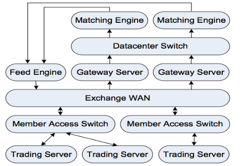
As a rule, three main entities are involved in the process of online trading - this is the exchange itself, tools for processing data flows from it and market participants, that is, traders. The exchange receives orders to buy or sell through the so-called gateway servers. Then the trading engine of the exchange tries to “reduce” buyers and sellers. If the transaction was successful, participants receive a notification about this. If the transaction has not yet passed and the order is in the queue, it can still be canceled.
Data flow processors receive information about current stock prices and the queue of buy or sell orders. This information is transmitted by the exchange and should be broadcast to interested bidders as soon as possible. The FAST protocol is often used to transport data. Imagine the above trading infrastructure in the form of a scheme:
Protocol stack
In modern implementations of electronic commerce systems, several levels of protocols are used.
TCP / IP, UDP and Ethernet
The basic communication protocol used by exchanges and other market participants. Non-critical information such as stock price data is transmitted over UDP to increase speed, critical information about trading orders is transmitted over TCP / IP. Accordingly, any trading system should be able to work effectively with these protocols. In the current implementation, this UDP processing task is transferred directly to the hardware.
Fast
To transfer large amounts of financial data without increasing delays, the FAST protocol was developed. FAST messages consist of various fields and operators. The protocol works on top of UDP - to reduce delays, several messages are placed in one UDP frame. FAST messages do not contain size information and do not set frame options. Instead, each message is defined by a template that must be known in advance - the only way to decrypt the data stream.
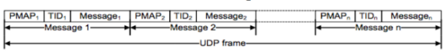
UDP frame with multiple FAST messages
Each message begins with a “presence card” (PMAP) and a template identifier (TID). PMAP is a mask that is used to indicate which of certain fields, sequences, or groups refers to the current stream. TID is used to determine the pattern that is needed to decode the message. Templates are described using XML, as in the example below:
Here TID equals 1, the template consists of two fields and one group. The field can be a string, an integer, with or without a sign, 32, 64-bit or decimal.
Data compression is implemented by removing leading zeros within each data word. Stop bits are used to decode compressed data. The first seven bits of each byte are used to encode data. The eighth bit is used as a stop bit to separate fields. For decompression, this stop bit must be deleted, and the remaining 7 bits must be shifted and concatenated in all cases when the field is more than one byte.
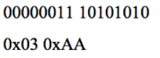
If there is the following binary input stream:
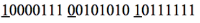
These three bytes represent two fields, as indicated by the underlined stop bits. To find out the real value of the first field, assuming that it is an integer, it is enough to replace the eighth bit with zero. The result will be as follows (binary and hexadecimal value):
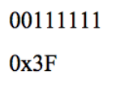
The second field spans two bytes. To find out its real value, for the first seven bits of each byte you need to perform concatenation and add two zero bits. The binary and hexadecimal result will look like this:
Making decisions
One of the most important aspects of the algorithmic trading system is making decisions about financial transactions. In order to decide whether to buy or sell a stock, a large amount of data and resources may be required to process it. The system can take into account many parameters and variables, which are compared using tools of mathematics and statistics.
In this article we will not consider the decision-making process in detail, we will only say that because of its complexity, it is never taken directly to the hardware, and remains the prerogative of software.
Base implementation
FPGAs are often used to create modern online trading systems. This iron is given the tasks of processing Ethernet, IP, UDP connections and decoding the FAST protocol. FPGA parallelism can achieve a significant increase in speed compared to exclusively software tools. The architecture of the system described in this work looks like this:
IP, UDP and ETH decoding on hardware
To reduce delays in the processing of market data, work with the IP, UDP and Ethernet stack is entirely made up of hardware. In this case, Xilinx Virtex-6 FPGA is used, which has high-speed serial transceivers, which can work as PHY for direct access to a 10Gbit Ethernet network switch.
Work with Ethernet MAC and protocols of other levels is carried out by internal modules. All elements are implemented at the RTL level (Register Transfer Level) using finite state machines. Iron operates at a frequency of 165 MHz and provides a 64-bit data bus, which allows to achieve a "processor" bandwidth of 1.25 GB / s, which corresponds to an input stream of 10 Gbit / s.
FAST decoding on iron
To achieve even greater performance of the trading system, decoding of the FAST protocol is also carried out in the iron part. However, this process is more complicated than working with regular UDP, which is almost the same for different applications. FAST is a much more original and flexible protocol - each handler can define its own template and presence cards, which makes implementation using state machines impossible.
Therefore, on the iron side, a module for working with microcodes was created, which can decode any implementation of FAST. In order to achieve support for the new protocol implementation, it is only necessary to create a microcode instruction. In this case, you do not need to make any modifications to the hardware itself.
The microcode stands out from the specification written in the domain-specific language DSL. Using a microcode module instead of a conventional processor allows you to achieve greater speed. Due to the limited set of instructions used, the data processing speed increases by several orders of magnitude.
The figure below shows the implementation of the FAST decoder. Each stage uses FIFO buffers. Each of the three stages operates at a frequency of 200 MHz and uses a 64-bit data path. The resource consumption during FAST processing is 5630 LUT (Lookup Tables).
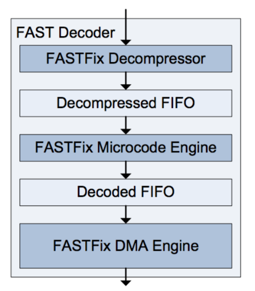
Briefly go through the other modules of the system:
- FAST decompressor - detects stop bits and aligns incoming fields.
- FAST microcode module - launches a program that loads into FPGA at startup and sets a route for each template.
- FAST direct access engine - to transfer the decoded FAST stream to trading software, a special direct access engine was created. It transfers the received data directly to the buffer, to which the software accesses, bypassing the operating system level.
- Subject oriented language
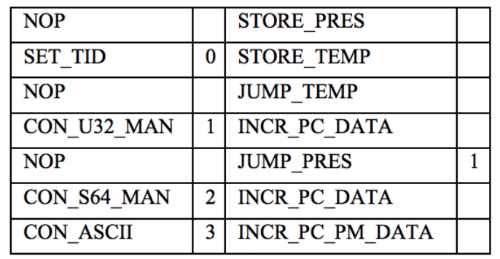
The binary code for the microcode module is created by the assembler using the DSL implementation developed specifically for this project. The assembler code for the template presented above might look something like this:
FAST Protocol Analysis
In order to create a system that could work effectively in all market conditions, even at times of high volatility and trading activity, a deep analysis of FAST data is required. First of all, you need to determine how fast the data update in a real trading system can be. For this, a theoretical model was developed that describes the upper limit of the speed of updating information and takes into account various data compression mechanisms.
In the next step, a more realistic model was developed, based on the numbers obtained in the course of real trading.
The formula below shows the data transfer rate, which is provided by the mechanisms for transmitting data feeds:
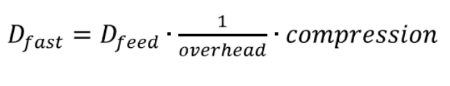
Here, compression is the compression factor of the FAST protocol, and overhead is the overhead of the Ethernet and UDP protocols. The maximum data development speed that a trading accelerator can support can be described as:
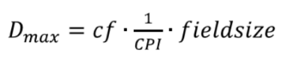
where cf is the clock frequency, CPI means the number of cycles per instruction, and fieldsize represents the number of bits per field / instruction.
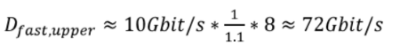
To calculate the upper limit of Dfast, you can choose the theoretical maximum for Dfeed, which is 10 Gb / s, and the compression ratio, which is 8 (64 bits can be compressed to a byte size). To obtain a realistic overhead estimate, several gigabytes of market data were analyzed. The overhead of UDP and Ethernet depends on the size of the packets and many other factors, but the researchers were able to determine the median overhead for the Ethernet, IP and UDP frames - it amounted to 10%.
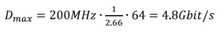
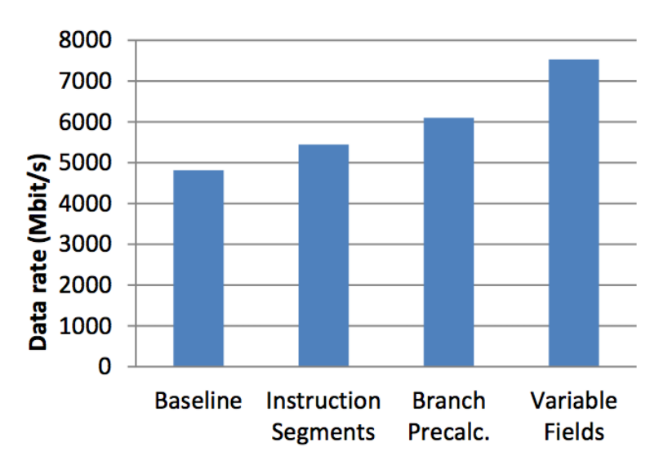
In the same way, you can calculate a stable data transfer rate Dmax, which can be "digested" by the trading accelerator. The field size is 64 bits, and cf is 200 MHz. As for the CPI parameter, the analysis shows that in the current implementation of the system 2.66 cycles are required for processing the field, which leads to a maximum data processing speed of the FAST processor of 4.8 Gb / s:
Since Dmax <Dfast, it is obvious that in times of bursts of market activity, the system simply cannot cope with the increased volumes of data. The only parameter that can be improved somehow is CPI. And you can do this using three techniques.
Segments of “custom” instructions
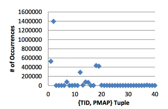
FAST message decoding is carried out according to certain rules, which are set using TID and PMAP. For each incoming message, the microcode module performs TID analysis to find the code of the instruction that needs to be executed for this 9 pattern. Inside the instruction stream, further branches that need to be processed are indicated by PMAP. The obvious solution, which significantly reduces the number of branches used, is to use discrete microcode segments not only for each template, but also for each sequence {TID, PMAP}, since it is this pair that predetermines all message branches.
The downside of this method is the increase in overhead performance. The size of the instruction is also seriously growing. Nevertheless, the analysis of large volumes of FAST data leads to interesting conclusions. Observations show that for five sequences {TID, PMAP} the probability of their occurrence is 92%. Therefore, it may make sense to implement microcode segments specifically for these pairs. The implementation of this approach can significantly reduce CPI - during the tests, the indicator was reduced from 2.66 to 2.35 - that is, the improvement was 13%.
Preliminary calculation of branches
Each branch of instructions requires three clock cycles and the use of two NOP instructions in the execution input. In this implementation, there are two types of branch instructions. The first uses the TID to find the segment of the instruction pointer, and the second instruction is used to branch inside the microcode segment. You can eliminate the delay in viewing a template segment by previewing the input fields and redirecting this information to memory. Since UDP frames contain a large number of templates, TID searches are often performed, which means that there is scope for optimization.
Processing Variable Length Fields
Another source of instruction branches may be the processing of variable-length fields. Because of the stop bits, the values in the compression scheme inside the FAST stream can have a size of 8 to 72 bits (64 bits + 8 stop bits). Since the data path is only 64 bits, the processing is extended to an additional one or two cycles. This also leads to additional NOP loops.
You can correct the situation by increasing the data path to 72 bits and decompressing the fields as an integer. In the case where the field is a number, it can be processed directly. In other cases, the additional 8 bits are simply ignored. This approach avoids the appearance of instruction branches; the implementation of variable-length fields has reduced the CPI from 2.1 to 1.7.
Rating
To evaluate the performance of the system using various optimization techniques, the results of its work were compared with the base implementation. The figure below shows the results of applying optimization techniques to increase the amount of processed data:
Also, the FPGA implementation was compared with software running on ordinary hardware (Intel Xeon 5472 and IBM Power6). The following is a comparison of performance in these cases:
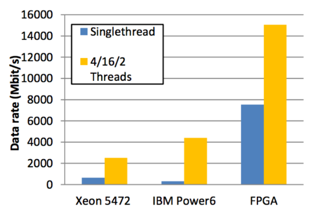
FAST message processing speed is also significantly different. In order to decode a FAST message with a length of 21 bytes, the implementation on Intel Xeon required 261 ns, IBM Power6 took 476 ns, and the FPGA implementation only 40 ns.