Kinect v2 calibration using OpenCV in Python
Not so long ago, we started a couple of projects that needed an optical system with a range channel, and decided to use Kinect v2 for this. Since the projects are implemented in Python, first you had to make Kinect work from Python, and then calibrate it, since Kinect out of the box introduces some geometric distortion into the frames and gives centimeter errors in determining the depth.
Before that, I had never dealt with computer vision, nor with OpenCV, nor with Kinect. I also could not find comprehensive instructions on how to work with all this economy, so in the end I had to tinker with order. And I decided that it would not be superfluous to systematize the experience gained in this article. Perhaps it will turn out to be worthless for some suffering person,and we also need a popular article for a tick in reporting .
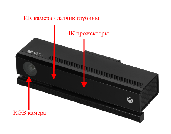
Minimum system requirements : Windows 8 and above, Kinect SDK 2.0, USB 3.0.
Table I. Kinect v2 Features:
Thus, I had the following tasks:
And now let us dwell on each item in detail.
As I said before, I had no business with computer vision, but rumors reached me that without the OpenCV library there is nowhere. And since it has a whole module for calibrating cameras, the first thing I did was build OpenCV with Python 3 support under Windows 8.1. It was not without some trouble that usually accompanies the assembly of open-source projects on Windows, but everything went without any special surprises and, in general, as part of the instructions from the developers.
With Kinect, I had to tinker a bit longer. The official SDK only supports interfaces for C #, C ++ and JavaScript. If you go on the other hand, you can see that OpenCV supportsinput from 3D cameras, but the camera must be compatible with the OpenNI library. OpenNI supports Kinect, but the relatively recent Kinect v2 does not. However, kind people wrote a driver for Kinect v2 under OpenNI. It even works and allows you to enjoy the video from the device’s channels in NiViewer, but when used with OpenCV it crashes with an error. However, other good people wrote a Python wrapper over the official SDK. I stopped at it.
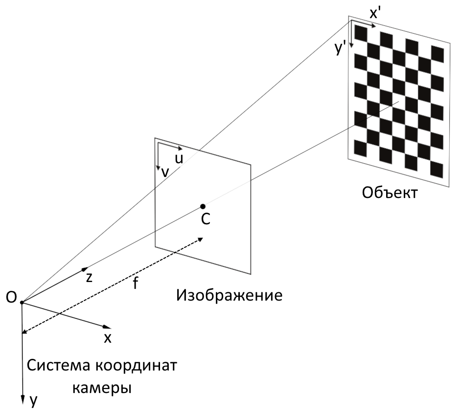
The cameras are not perfect, they distort the picture and need calibration. To use Kinect for measurements, it would be nice to eliminate these geometric distortions on both the RGB camera and the depth sensor. Since the IR camera is also the receiver of the depth sensor, we can use IR frames for calibration, and then use the calibration results to eliminate distortions from depth frames.
Calibration of the camera is carried out in order to find out the internal parameters of the camera, namely, the camera matrix and distortion coefficients.
A camera matrix is a matrix of the form:
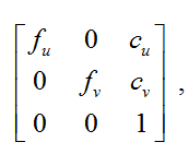 where
where
( with u , c v) - coordinates of the principle point (the point of intersection of the optical axis with the image plane, in the ideal camera, it is located exactly in the center of the image, in real ones it is slightly offset from the center);
f u , f v - focal length f , measured in the width and height of the pixel.
There are two main types of distortion: radial distortion and tangential distortion.
Radial distortion - image distortion as a result of non-ideal parabolic shape of the lens. The distortion caused by radial distortion is equal to 0 in the optical center of the sensor and increases towards the edges. Typically, radial distortion contributes most to image distortion.
Tangential distortion- image distortion caused by errors in the installation of the lens parallel to the image plane.
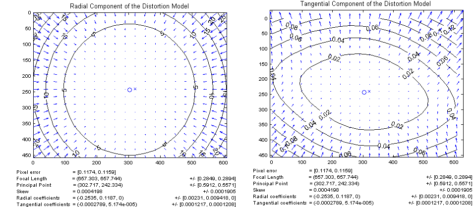
To eliminate distortion, the coordinates of the pixels can be recalculated using the following equation :

where ( u, v ) is the initial pixel location,
( u corrected , v corrected ) is the pixel location after geometric distortions are eliminated,
k 1 , k 2 , k 3 are the radial distortion coefficients ,
p 1 , p 2 - tangential distortion coefficients,
r 2 = u 2 + v 2 .
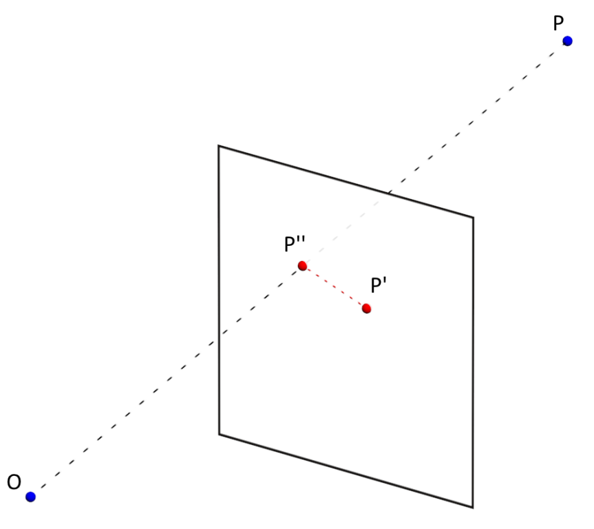
The accuracy of measuring camera parameters (distortion coefficients, camera matrix) is determined by the average value of the reprojection error ( ReEr, Reprojection Error ). ReEr - distance (in pixels) between the projection P ' on the image plane of point P on the surface of the object, and the projection P' 'of the same point P , constructed after eliminating distortion using camera parameters.
The standard procedure for calibrating the camera consists of the following steps:
1) take 20-30 photos with different positions of theobject with the known geometry of the chessboard;

2) determine the key points of the object in the image;
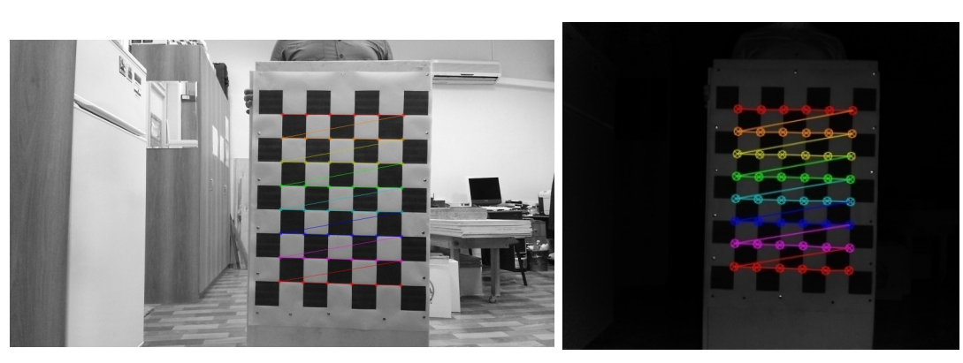
3) find such distortion factors that minimizes ReEr .
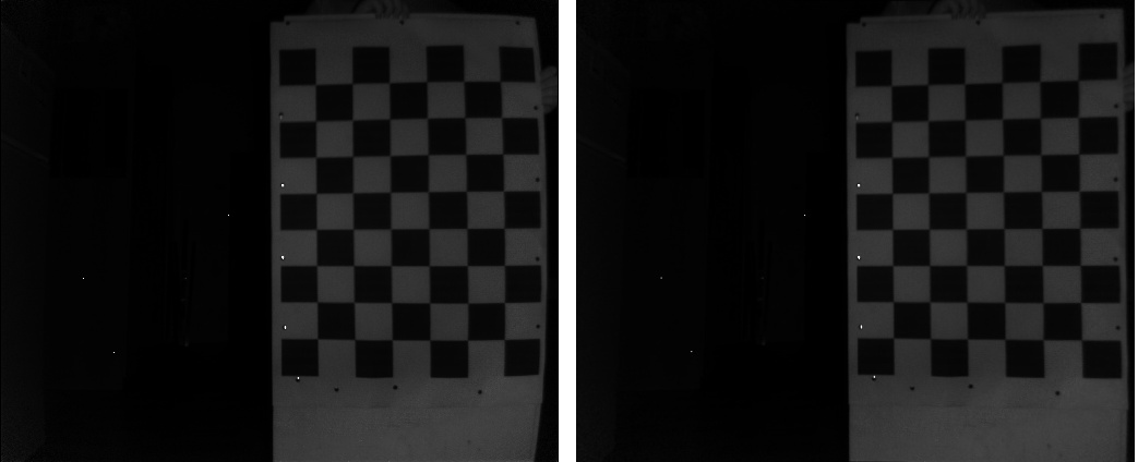
In our case, the average ReEr value for an RGB camera was 0.3 pixels, and for an IR camera - 0.15. Distortion elimination results:
In order to get both depth (Z coordinate) and color for a pixel, first you need to go from the pixel coordinates on the depth frame to the three-dimensional coordinates of the IR camera [2]:
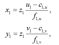
where ( x 1 , y 1 , z 1 ) are the coordinates of the point in the coordinate system of the IR camera,
z 1 is the result returned by the depth sensor,
( u 1 , v 1 ) is the pixel coordinate on the depth frame,
c 1, u , c 1, v are the coordinates of the optical center of the IR camera,
f 1, u , f 1, v - projection of the focal length of the IR camera.
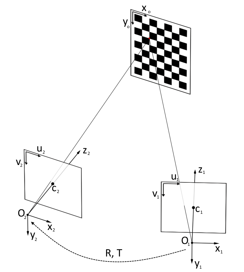
Then you need to go from the coordinate system of the IR camera to the coordinate system of the RGB camera. To do this, you need to move the origin using the transfer vector T and rotate the coordinate system using the rotation matrix R :
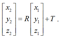
After that, we need to switch from the three-dimensional coordinate system of the RGB camera to the pixel coordinates of the RGB frame:
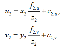
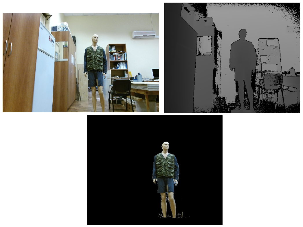
Thus, after all these transformations, we can get for the pixel ( u 1 , v 1 ) frame depth color value of the corresponding pixel of the RGB frame ( u 2 , v 2 ).
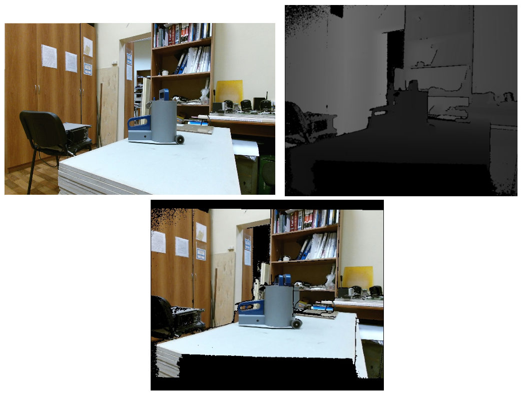
As you can see in the resulting picture, the image is doubled in places. The same effect can be observed.and when using the CoordinateMapper class from the official SDK. However, if only a person is interested in the image, then you can use bodyIndexFrame (a Kinect stream that lets you know which pixels belong to the person and which to the background) to highlight the area of interest and eliminate ghosting.
To determine the rotation matrix R and the transfer vector T, it is necessary to carry out a joint calibration of two chambers. To do this, you need to take 20-30 photographs of an object with known geometries in various positions of both RGB and an IR camera, it is better not to hold the object in your hands in order to exclude the possibility of its displacement between shooting frames by different cameras. Then you need to use the stereoCalibrate functionfrom the OpenCV library. This function determines the position of each of the cameras relative to the calibration object, and then finds such a transformation from the coordinate system of the first camera to the coordinate system of the second camera that minimizes ReEr.
And in the end, we got ReEr = 0.23.
The Kinect depth sensor returns the depth (namely depth, i.e. the Z-coordinate, not the distance) in mm. But how accurate are these values? Judging by the publication [2], the error can be 0.5-3 cm depending on the distance, so it makes sense to calibrate the depth channel.
This procedure is to find the Kinect systematic error (the difference between the reference depth and the depth produced by the sensor) depending on the distance to the object. And for this you need to know the reference depth. The most obvious way is to place a flat object parallel to the plane of the camera and measure the distance to it with a ruler. By gradually moving the object and making a series of measurements at each distance, you can find the average error for each of the distances. But, firstly, it is not very convenient, and secondly, it’s more difficult to find a perfectly flat object of relatively large size and to ensure that it is parallel to the plane of the camera than it might at first glance. Therefore, as a standard against which the error will be calculated, we decided to take the depth, determined by the known geometry of the object.
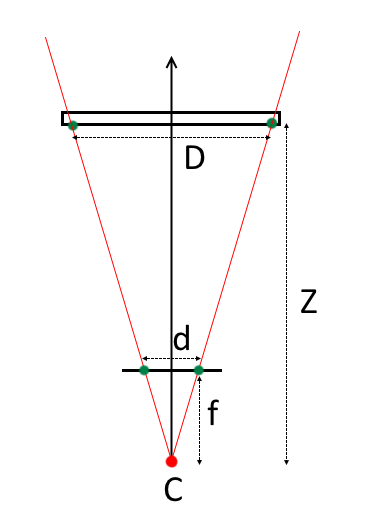
Knowing the geometry of the object (for example, the size of the cells of a chessboard) and placing it strictly parallel to the plane of the camera, you can determine the depth to it as follows:
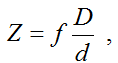
where f is the focal length,
d is the distance between the projections of the key points on the camera’s matrix,
D is the distance between the key points of the object,
Z is the distance from the center of the projection of the camera to the object.
If the object is not located strictly parallel, but at a certain angle to the plane of the camera, the depth can be determined based on the solution of the Perspective-n-Point (PnP) problem [3]. A number of algorithms implemented in the OpenCV library are dedicated to solving this problem, which allow you to find the transformation | R, T| between the coordinate system of the calibration object and the camera coordinate system, and therefore, determine the depth accurate to the camera parameters.
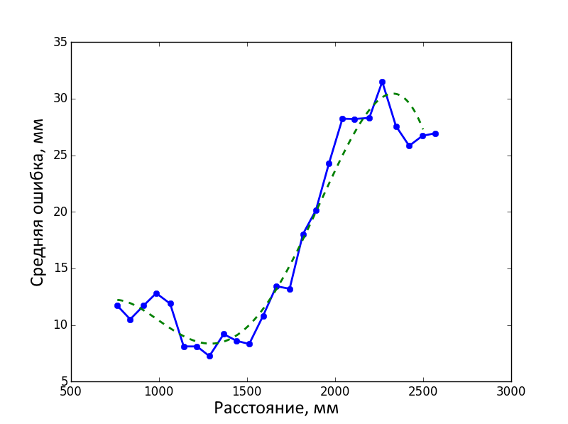
To calibrate the depth channel, we performed a series of surveys of the calibration object at distances of ~ 0.7-2.6 m in steps of ~ 7 cm. The calibration object was located in the center of the frame parallel to the plane of the camera, as far as possible “by eye”. At each distance, one shot was taken with an RGB camera and 100 shots with a depth sensor. The data from the sensor was averaged, and the distance determined by the geometry of the object based on the RGB frame was taken as the standard. The average error in determining the depth by the Kinect sensor at a given distance was determined as follows:
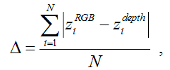
where z i RGB is the distance to the ith key point over geometry,
z i depth is the distance averaged over 100 frames to the i-th key point according to the depth sensor,
N is the number of key points on the object (in our case, 48).
Then we got the error function from the distance by interpolating the results.
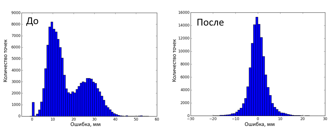
The figure below shows the distribution of errors before and after correction on calibration frames. A total of 120,000 measurements were made (25 distances, 100 depth frames on each, 48 key points on the object). The error before correction was 17 ± 9.95 mm (mean ± standard deviation), after - 0.45 ± 8.16 mm.
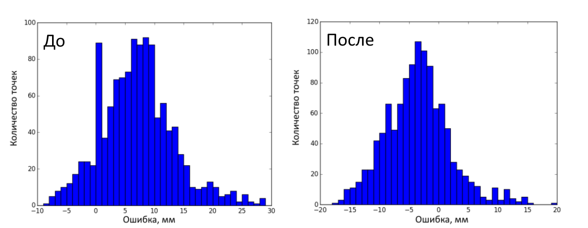
Then 25 test frames (RGB and depth) of the calibration object in various positions were made. A total of 1200 measurements (25 frames, 48 key points on each). The error before correction was 7.41 ± 6.32 mm (mean ± standard deviation), after - 3.12 ± 5.50 mm. The figure below shows the distribution of errors before and after correction on test frames.
Thus, we eliminated the geometric distortions of the RGB camera and the depth sensor, learned how to combine frames and improved the accuracy of determining the depth. The code for this project can be found here . I hope it turns out to be useful.
The study was carried out with a grant from the Russian Science Foundation (project No. 15-19-30012)
1. Kramer J. Hacking the Kinect / Apress. 2012. P. 130
2. Lachat E. et al. First Experiences With Kinect V2 Sensor for Close Range 3D Modeling // International Archives of the Photogrammetry, Remote Sensing and Spatial Information Sciences. 2015.
3. Gao XS et al. Complete solution classification for the perspective-three-point problem // IEEE Transactions on Pattern Analysis and Machine Intelligence. Vol. 25. N 8. 2003. P. 930-943.
Before that, I had never dealt with computer vision, nor with OpenCV, nor with Kinect. I also could not find comprehensive instructions on how to work with all this economy, so in the end I had to tinker with order. And I decided that it would not be superfluous to systematize the experience gained in this article. Perhaps it will turn out to be worthless for some suffering person,
Minimum system requirements : Windows 8 and above, Kinect SDK 2.0, USB 3.0.
Table I. Kinect v2 Features:
| Resolution RGB camera, pix. | 1920 x 1080 |
| Resolution infrared (IR) camera, pix. | 512 x 424 |
| Viewing angles of the RGB camera, º | 84.1 x 53.8 |
| Viewing angles of the IR camera, º | 70.6 x 60.0 |
| Range of measurements of range, m. | 0.6 - 8.0 1 |
| The shooting frequency of the RGB camera, Hz | thirty |
| IR camera shooting frequency, Hz | thirty |
1
Information differs from source to source. Then talk about 0.5-4.5 m., In fact I was getting ~ 0.6-8.0 m.
Thus, I had the following tasks:
- get Kinect in Python;
- calibrate RGB and IR cameras;
- realize the ability to combine RGB and IR frames;
- calibrate the depth channel.
And now let us dwell on each item in detail.
1. Kinect v2 and Python
As I said before, I had no business with computer vision, but rumors reached me that without the OpenCV library there is nowhere. And since it has a whole module for calibrating cameras, the first thing I did was build OpenCV with Python 3 support under Windows 8.1. It was not without some trouble that usually accompanies the assembly of open-source projects on Windows, but everything went without any special surprises and, in general, as part of the instructions from the developers.
With Kinect, I had to tinker a bit longer. The official SDK only supports interfaces for C #, C ++ and JavaScript. If you go on the other hand, you can see that OpenCV supportsinput from 3D cameras, but the camera must be compatible with the OpenNI library. OpenNI supports Kinect, but the relatively recent Kinect v2 does not. However, kind people wrote a driver for Kinect v2 under OpenNI. It even works and allows you to enjoy the video from the device’s channels in NiViewer, but when used with OpenCV it crashes with an error. However, other good people wrote a Python wrapper over the official SDK. I stopped at it.
2. Camera calibration
The cameras are not perfect, they distort the picture and need calibration. To use Kinect for measurements, it would be nice to eliminate these geometric distortions on both the RGB camera and the depth sensor. Since the IR camera is also the receiver of the depth sensor, we can use IR frames for calibration, and then use the calibration results to eliminate distortions from depth frames.
Calibration of the camera is carried out in order to find out the internal parameters of the camera, namely, the camera matrix and distortion coefficients.
A camera matrix is a matrix of the form:
where ( with u , c v) - coordinates of the principle point (the point of intersection of the optical axis with the image plane, in the ideal camera, it is located exactly in the center of the image, in real ones it is slightly offset from the center);
f u , f v - focal length f , measured in the width and height of the pixel.
There are two main types of distortion: radial distortion and tangential distortion.
Radial distortion - image distortion as a result of non-ideal parabolic shape of the lens. The distortion caused by radial distortion is equal to 0 in the optical center of the sensor and increases towards the edges. Typically, radial distortion contributes most to image distortion.
Tangential distortion- image distortion caused by errors in the installation of the lens parallel to the image plane.
To eliminate distortion, the coordinates of the pixels can be recalculated using the following equation :
where ( u, v ) is the initial pixel location,
( u corrected , v corrected ) is the pixel location after geometric distortions are eliminated,
k 1 , k 2 , k 3 are the radial distortion coefficients ,
p 1 , p 2 - tangential distortion coefficients,
r 2 = u 2 + v 2 .
The accuracy of measuring camera parameters (distortion coefficients, camera matrix) is determined by the average value of the reprojection error ( ReEr, Reprojection Error ). ReEr - distance (in pixels) between the projection P ' on the image plane of point P on the surface of the object, and the projection P' 'of the same point P , constructed after eliminating distortion using camera parameters.
The standard procedure for calibrating the camera consists of the following steps:
1) take 20-30 photos with different positions of the
2) determine the key points of the object in the image;
found, corners = cv2.findChessboardCorners(img, #изображение
					    PATTERN_SIZE,#сколько ключевых точек, в нашем случае 6x8
					    flags)#параметры поиска точек
3) find such distortion factors that minimizes ReEr .
ReEr, camera_matrix, dist_coefs, rvecs, tvecs = cv2.calibrateCamera(obj_points,#координаты ключевых точек в системе координат объекта
                                                                    #(х', y', z'=0)
                                                                    img_points,#в системе координат изображения (u,v)
                                                                    (w, h),#размер изображения
                                                                    None,#можно использовать уже известную матрицу камеры
                                                                    None, #можно использовать уже известные коэффициенты дисторсии
                                                                    criteria = criteria,#критерии окончания минимизации ReEr
		                                                    flags = flags)#какие коэффициенты дисторсии мы хотим получить
In our case, the average ReEr value for an RGB camera was 0.3 pixels, and for an IR camera - 0.15. Distortion elimination results:
img = cv2.undistort(img, camera_matrix, dist_coefs)
3. Combining frames from two cameras
In order to get both depth (Z coordinate) and color for a pixel, first you need to go from the pixel coordinates on the depth frame to the three-dimensional coordinates of the IR camera [2]:
where ( x 1 , y 1 , z 1 ) are the coordinates of the point in the coordinate system of the IR camera,
z 1 is the result returned by the depth sensor,
( u 1 , v 1 ) is the pixel coordinate on the depth frame,
c 1, u , c 1, v are the coordinates of the optical center of the IR camera,
f 1, u , f 1, v - projection of the focal length of the IR camera.
Then you need to go from the coordinate system of the IR camera to the coordinate system of the RGB camera. To do this, you need to move the origin using the transfer vector T and rotate the coordinate system using the rotation matrix R :
After that, we need to switch from the three-dimensional coordinate system of the RGB camera to the pixel coordinates of the RGB frame:
Thus, after all these transformations, we can get for the pixel ( u 1 , v 1 ) frame depth color value of the corresponding pixel of the RGB frame ( u 2 , v 2 ).
As you can see in the resulting picture, the image is doubled in places. The same effect can be observed.and when using the CoordinateMapper class from the official SDK. However, if only a person is interested in the image, then you can use bodyIndexFrame (a Kinect stream that lets you know which pixels belong to the person and which to the background) to highlight the area of interest and eliminate ghosting.
To determine the rotation matrix R and the transfer vector T, it is necessary to carry out a joint calibration of two chambers. To do this, you need to take 20-30 photographs of an object with known geometries in various positions of both RGB and an IR camera, it is better not to hold the object in your hands in order to exclude the possibility of its displacement between shooting frames by different cameras. Then you need to use the stereoCalibrate functionfrom the OpenCV library. This function determines the position of each of the cameras relative to the calibration object, and then finds such a transformation from the coordinate system of the first camera to the coordinate system of the second camera that minimizes ReEr.
retval, cameraMatrix1, distCoeffs1, cameraMatrix2, distCoeffs2, R, T, E, F = cv2.stereoCalibrate(pattern_points, #координаты ключевых
                                                          #точек в системе координат объекта (х', y', z'=0)
                                                          ir_img_points,#в системе координат ИК камеры (u1, v1)
                                                          rgb_img_points, #в системе координат RGB камеры (u2, v2)
                                                          irCamera['camera_matrix'],#матрица камеры ИК (брать из calibrateCamera),
                                                          irCamera['dist_coefs'], #коэф. дис. ИК камеры (брать из calibrateCamera)
                                                          rgbCamera['camera_matrix'], #матрица RGB камеры (брать из calibrateCamera)
                                                          rgbCamera['dist_coefs'], #коэф. дис. RGB камеры (брать из calibrateCamera)
                                                          image_size) #размер изображения ИК камеры (в пикселях)
And in the end, we got ReEr = 0.23.
4. Calibration of the depth channel
The Kinect depth sensor returns the depth (namely depth, i.e. the Z-coordinate, not the distance) in mm. But how accurate are these values? Judging by the publication [2], the error can be 0.5-3 cm depending on the distance, so it makes sense to calibrate the depth channel.
This procedure is to find the Kinect systematic error (the difference between the reference depth and the depth produced by the sensor) depending on the distance to the object. And for this you need to know the reference depth. The most obvious way is to place a flat object parallel to the plane of the camera and measure the distance to it with a ruler. By gradually moving the object and making a series of measurements at each distance, you can find the average error for each of the distances. But, firstly, it is not very convenient, and secondly, it’s more difficult to find a perfectly flat object of relatively large size and to ensure that it is parallel to the plane of the camera than it might at first glance. Therefore, as a standard against which the error will be calculated, we decided to take the depth, determined by the known geometry of the object.
Knowing the geometry of the object (for example, the size of the cells of a chessboard) and placing it strictly parallel to the plane of the camera, you can determine the depth to it as follows:
where f is the focal length,
d is the distance between the projections of the key points on the camera’s matrix,
D is the distance between the key points of the object,
Z is the distance from the center of the projection of the camera to the object.
If the object is not located strictly parallel, but at a certain angle to the plane of the camera, the depth can be determined based on the solution of the Perspective-n-Point (PnP) problem [3]. A number of algorithms implemented in the OpenCV library are dedicated to solving this problem, which allow you to find the transformation | R, T| between the coordinate system of the calibration object and the camera coordinate system, and therefore, determine the depth accurate to the camera parameters.
retval, R, T = cv2.solvePnP(obj_points[:, [0, 5, 42, 47]],#крайние точки в координатах объекта
			    img_points[:, [0, 5, 42, 47]], #крайние точки в координатах изображения
			    rgbCameraMatrix,#матрица камеры
                            rgbDistortion,#коэффициенты дисторсии
                            flags= cv2.SOLVEPNP_UPNP)#метод решения PnP
R, jacobian = cv2.Rodrigues(R)#переходим от вектора вращения к матрице вращения
for j in range(0, numberOfPoints): # цикл по ключевым точкам
    point = numpy.dot(rgb_obj_points[j], R.T) + T.T # Важно! В документации нигде об этом не сказано,
    #но по итогам экспериментов с модельными изображениями, выяснилось, что нужно транспонировать матрицу вращения
    computedDistance[j] = point[0][2] * 1000 # Z-координата в мм
To calibrate the depth channel, we performed a series of surveys of the calibration object at distances of ~ 0.7-2.6 m in steps of ~ 7 cm. The calibration object was located in the center of the frame parallel to the plane of the camera, as far as possible “by eye”. At each distance, one shot was taken with an RGB camera and 100 shots with a depth sensor. The data from the sensor was averaged, and the distance determined by the geometry of the object based on the RGB frame was taken as the standard. The average error in determining the depth by the Kinect sensor at a given distance was determined as follows:
where z i RGB is the distance to the ith key point over geometry,
z i depth is the distance averaged over 100 frames to the i-th key point according to the depth sensor,
N is the number of key points on the object (in our case, 48).
Then we got the error function from the distance by interpolating the results.
The figure below shows the distribution of errors before and after correction on calibration frames. A total of 120,000 measurements were made (25 distances, 100 depth frames on each, 48 key points on the object). The error before correction was 17 ± 9.95 mm (mean ± standard deviation), after - 0.45 ± 8.16 mm.
Then 25 test frames (RGB and depth) of the calibration object in various positions were made. A total of 1200 measurements (25 frames, 48 key points on each). The error before correction was 7.41 ± 6.32 mm (mean ± standard deviation), after - 3.12 ± 5.50 mm. The figure below shows the distribution of errors before and after correction on test frames.
Conclusion
Thus, we eliminated the geometric distortions of the RGB camera and the depth sensor, learned how to combine frames and improved the accuracy of determining the depth. The code for this project can be found here . I hope it turns out to be useful.
The study was carried out with a grant from the Russian Science Foundation (project No. 15-19-30012)
List of sources
1. Kramer J. Hacking the Kinect / Apress. 2012. P. 130
2. Lachat E. et al. First Experiences With Kinect V2 Sensor for Close Range 3D Modeling // International Archives of the Photogrammetry, Remote Sensing and Spatial Information Sciences. 2015.
3. Gao XS et al. Complete solution classification for the perspective-three-point problem // IEEE Transactions on Pattern Analysis and Machine Intelligence. Vol. 25. N 8. 2003. P. 930-943.