May 4, 2017 at 12:10
STC Metrotek. Part 2. Golden eagle-MMT and rake race
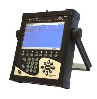
The last time I stopped the story on the fact that we took a chance to make your own modular device, so as not to tie development to third-party solutions such as the iPAQ handhelds, long-gone from the market, and repressed in the end smartphones.
So, 2005-2006.
Usually, the cycle of creating a new piece of iron in a company took six months - from the idea to the first serial production of aka mass production. By the way, the complexity of the upcoming development did not scare us at all. No wonder we chose the slogan "Challenges - simple solutions!". Moreover, as the main developer of iron believed, if the system has FPGA, then any hardware problems can be solved in a "software" way (for example, if the board was mistaken in designing the legs).
Okay, the decision is made - and away we go! Agreed TK: general requirements, form factor, approximate construct, structural diagram. Foreign competitors (Sunrise Telecom, Anritsu etc.) were dominated by a fixed configuration or, at most, a configuration with one replaceable module. We decided that in our device there will be two replaceable measuring modules and suggested that for a start we will release three types of cards: E1 / PCM, Datacom, Gigabit Ethernet.
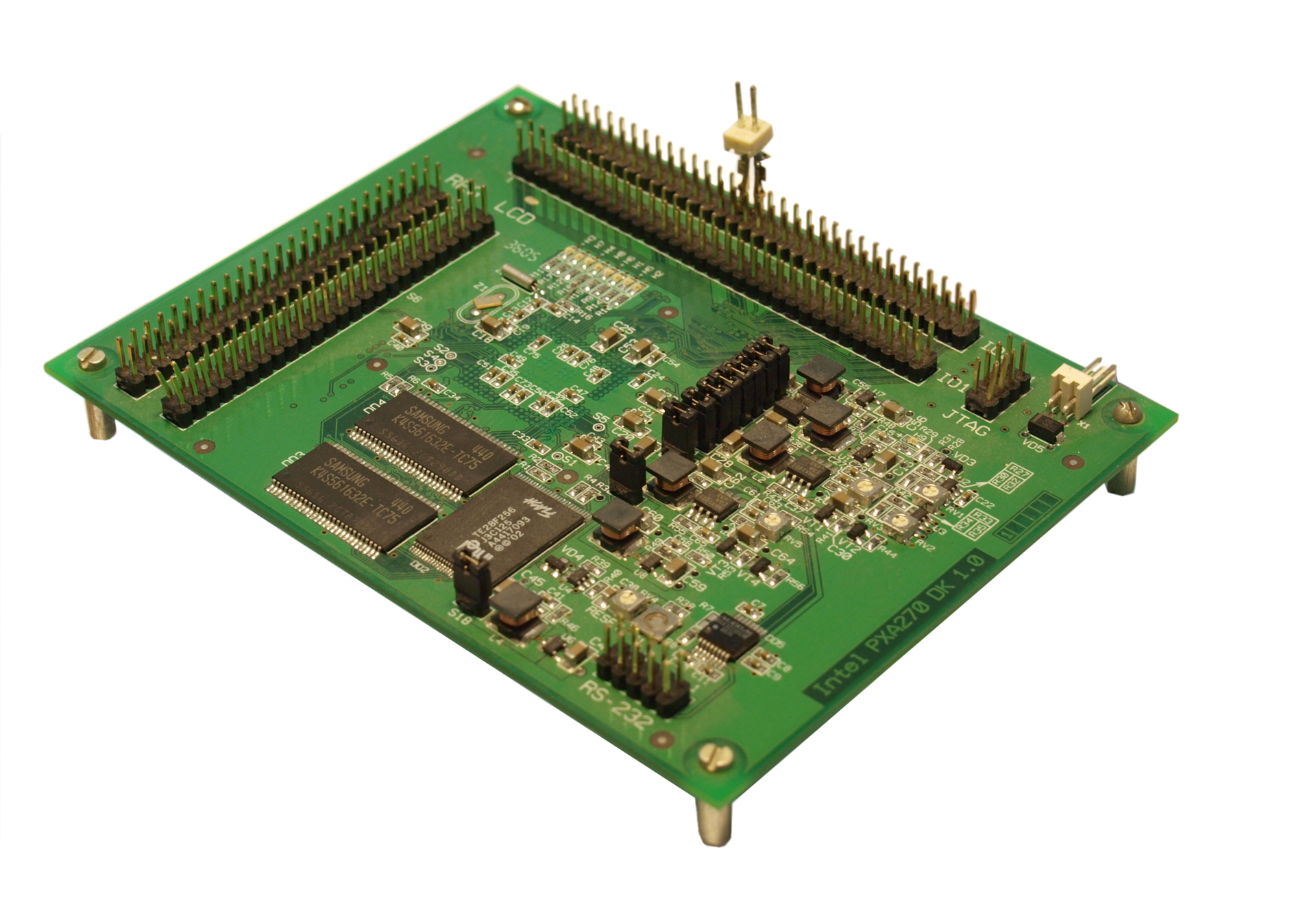
Since the development experience for the ARM processor of the Intel PXA250 family was available in full - if such a processor was installed in iPAQ handhelds - then we selected the Intel PXA270, which was new at that time, as the core of the control platform (then Intel gave these processors to the company Marvell), especially since the pilot board worked almost immediately and without any problems.
This is what the pilot looked like, in which, in a couple of days, using the rope loop and stick jtag and openocd, it was possible to start bootloader and linux, at the same time pointing Intel to the shortcomings in the documentation.
View from the processor:

View from the side of the comb for connecting peripherals:
But the choice and the rise of the central processor is not even half the battle, but at most one tenth. Because there are peripheral devices, such as a power and battery management controller, audio-codec, ethernet, usb, etc., built into the processor or stand-alone.
To avoid errors at the wiring level of the board, we made a "landmark" decision to make wiring of digital signals via FPGA and CPLD chips and this is what happened when looking at the first version of the device from the programmer’s point of view:
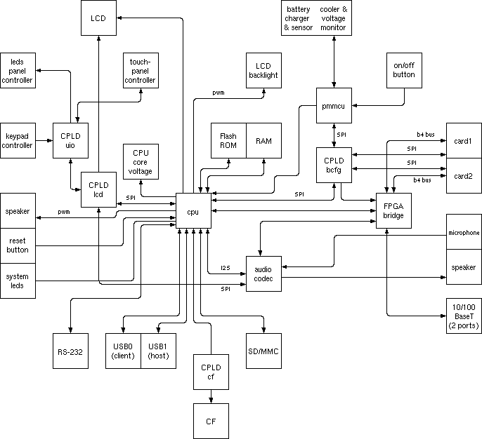
As you can easily figure out, almost all peripheral components are connected to the central processor via FPGAs (FPGA and CPLD): display, touch panel, audio, keyboard, LAN ports, interchangeable measuring modules, and even compact flash. And to manage the power and charge of the NiMh battery, we connected a separate controller based on ATMega, in which we implemented the functions of smart battery.
(Let me remind you that this was ten years ago and we knew about specialized microcircuits for charging and power control, but for some reason we didn’t particularly trust them. Now we can safely admit that yes, they were mistaken. It is not for nothing that companies producing such chips spend to develop for several years. Now we have become smarter and are not engaged in the invention of a bicycle.)
And here is the resulting monster - the main board of the device:
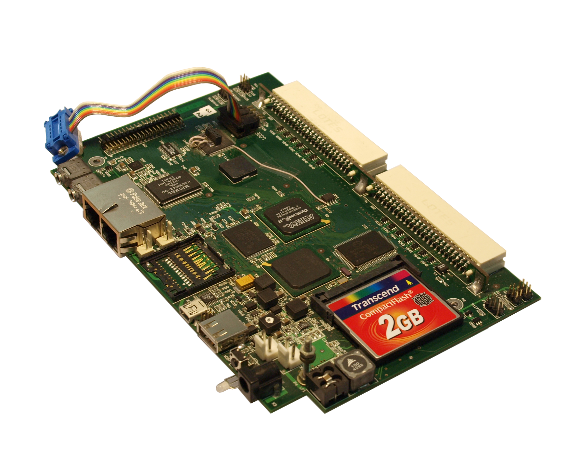
To connect plug-in modules, their own protocol for data exchange and control was invented, and the physical interface was implemented in the form factor of a stripped-down PCI connector:
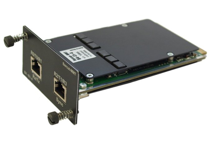
Above and below, there are protective panels so that curious users do not pick up unnecessary details, as it seemed to them, from the board.
Needless to say, the device turned out to be mega-complex both in development and in maintenance? In addition to application programs for measurements, it was necessary to develop many crutches and ropes of subsystems:
- FPGA and CPLD firmware for resolving SPI streams, for working with a paid ethernet controller, for exchanging with removable modules on a parallel bus, for transferring audio information from modules to an audio codec,
- drivers (linux kernel modules) for updating firmware and working with everything invented by the zoo,
- firmware for the charge and power control chip ...
But it is universal and insured against almost any errors in wiring. People, never do that!
Oh, how much easier our world was before we had to rush into the development of complex systems.
In addition to the FPGA installed on board (on the motherboard), each plug-in module also has its own FPGA, which implements real-time measurement logic and without which we can not do in our business, unlike the motherboard. The latter, by the way, has since undergone several reincarnations and has become an order of magnitude simpler and more reliable.
And in the new versions we didn’t pervert or invent a bicycle anymore: We used USB for exchange with plug-in modules, we took the processor board in SO-DIMM format, decidedly refused the special processors for monitoring and charging batteries and switched to standard BQ series microcircuits from Texas Instruments and happiness came.
As M. Zhvanetsky said in one of his miniatures: “but there is experience!”, And we try not to step on such a rake.
And if the system turned out to be as complicated as in our example, then most likely it was designed incorrectly.
To be continued.