Arduino + ESP8266 from scratch on the example of a Wi-Fi thermometer, part one
Part 1. Preparing ESP8266
Why this article? On the hub there are already a number of articles about the use of ESP in different configurations, but for some reason without details about how everything is connected, flashed and programmed. Like "I took an ESP, two finger batteries, a DHT22, put it in a box, shook the watch and the thermometer is ready!". As a result, it turns out strange: those who already work with ESP do not see anything unusual in what has been done, and those who want to learn do not understand where to start. Therefore, I decided to write a detailed article on how the ESP is connected and flashed, how to connect it with the Arduino and the outside world, and what problems I came across along the way. I provide links to Aliexpress only to represent the order of prices and the appearance of the components.
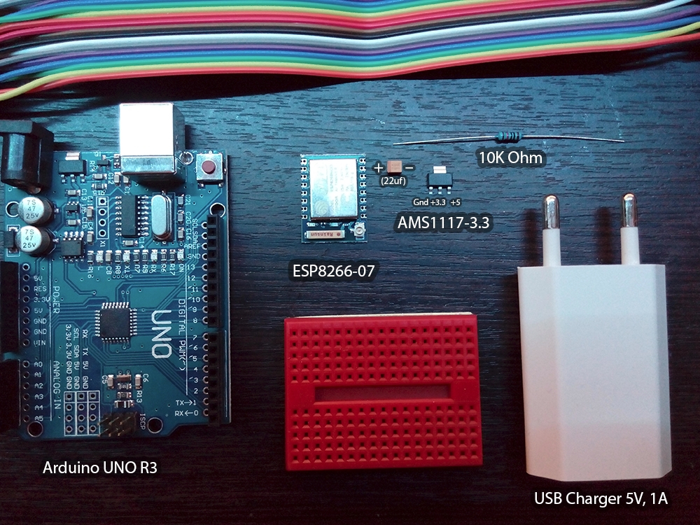
So, I had two microcontrollers, seven different sensors, five power supplies, a DHT22 temperature sensor and a whole host of wires of all kinds and colors, as well as countless resistances, capacitors and diodes. Not that all this was necessary for the thermometer, but if you already started to engage in microelectronics, it becomes difficult to stop.
Power Supply
For operation of the ESP8266, a voltage of 3.3 V and a current of at least 300 mA are required. Unfortunately, Arduino Uno is not able to provide such current, as it is not able to provide it with USB-UART adapters (programmers) like FT232RL - their limit is about 50mA. So you have to organize a separate meal. And it would be better if Arduino also worked from 3.3V to avoid problems like "I applied a five-volt signal to the output of the RX module of the ESP, why does it smell like plastic."
There are three solutions.
1. Buy a ready - made 3.3V power supply .
2. Buy a ready-made module with a voltage regulator that lowers 5V to 3.3V. Perhaps this is the most convenient option.
3. Assemble the module yourself from the AMS1117 controller and one 22uF tantalum capacitor.
I chose the third item, because I often need 3.3V, I'm greedy and I like to build regulators directly into power supplies.
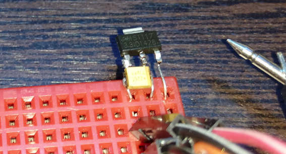
With AMS1117, everything is simple: if you put it text up, the voltage on the legs increases from left to right: 0 (Gnd), 3.3V (Vout), 5V (Vin).
Between zero and output, a 22mkF tantalum capacitor is needed (so according to the instructions , what will happen if I put an electrolytic one - I did not check). Tantalum SMD capacitor plus where the strip. A bit of a monstrous soldering of SMD components that are absolutely not intended for such barbarism and:
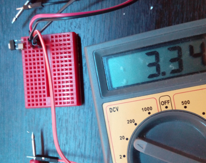
Be sure to check the output voltage. If it is significantly less than 3.3V (for example, 1.17V), let the regulator cool down after soldering and check the contacts. If you put the capacitor more than 22uF, the multimeter can show a higher voltage.
Why exactly AMS1117? It is widely used. You can find it almost everywhere, even in Arduino Uno, as a rule, it costs AMS1117-5.0.
If you know something of a similar size and price, even easier to use, please write.
An important point. I don’t know why, but AMS1117 is extremely moody about the quality of the connections. Contacts must be reliable. Better - soldered. Otherwise, it produces 3.3V in tests, but it does not produce anything under load.
Connect ESP8266
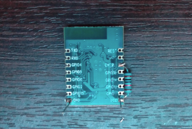
I chose model 07 because it has an excellent metal screen that works as protection against interference, mechanical stress and as a radiator. The latter provides the difference between a burnt module and a simply heated one. In addition, there is a jack for an external antenna.
To start the chip, you need to connect VCC and CH_P through a 10kΩ resistor. If this is not the case, then any one of the 1-20 kOhm range will do. In addition, specifically model 07 still requires that GPIO15 (the one closest to GND) be "on the ground" (this is not visible in the picture, because the connection is on the other hand).
Now we take the USB-UART adapter, switch it to 3.3V and connect RX to TX, TX to RX and GND to ground (I have unstable transmission without this). If you can’t switch to 3.3V, then you can usesimplest resistor voltage divider: connect the ESP RX to the TX adapter through a 1kΩ resistance, and the ESP RX to ground through a 2kΩ. There are many more complex and more reliable ways to connect 3.3V and 5V, but in this case it will do.

And we connect at a speed of 9600 on the desired COM port (you can see it in the device manager).

I use SecureCRT, Putty is fine too, and Linux connoisseurs already know what to do and where to watch.

(AT + RST reloads the chip)
If nothing happens - turn off - turn on the power, if nothing happens anyway - check the TX / RX correspondence, try to rearrange them or solder to the chip.
Sometimes the chip duringbullyingexperiments freezes and then it needs to be de-energized, including disconnecting the adapter (for example, pulling it out of USB), because the chip even has enough incoming power crumbs to stubbornly stub and not work.
Sometimes tricks with an adapter hang a USB port. You can use a different USB port as a temporary solution, but generally it is better to restart the computer.
Sometimes this changes the number of the COM port. Under Linux, this can be solved with udev.
If garbage comes instead of text, then check the speed settings. Some older chips run on 115200.
At the start, the chip heats up, but if it is really hot and continues to warm up - turn it off and check all the connections. So that + 3.3V does not get on the case, so that 5V does not come to it at all, so that the “ground” of the adapter is connected to the “ground” of the chip. Models with a metal screen are very difficult to burn (but nothing is impossible), and they complain about models without screens, saying that even a small mistake can be the last in the life of the chip. But I did not check it.
Firmware
My choice is NodeMCU . She has problems with memory and hardware support, but this is repeatedly paid for by the simplicity of the code and the ease of debugging. NodeMCU flasher and LuaLoader
will also be required (the latter is optional, there are other clients for working with this firmware).

Turn off the chip. We connect GPIO0 to the ground and turn on the chip:
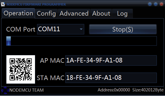
If nothing happens and the AP MAC / STA MAC fields are empty, check again that GPIO0 is on the ground.
If the firmware started, but it crashed - look in the Log tab, for some reason I specifically refused to flash the chip on the FT232RL, but it was flashed without problems on the PL2303HX at a speed of 576000. The PL2303HX in this version does not have a 3.3V switch to use it you need to open the plastic case and solder the wire from 5V to 3.3V, there are options with five outputs : 3.3, 5, TX, RX, Gnd.

Please note: STA MAC has changed. I suspect that flasher showed it incorrectly, but verification is required.
To save energy and nerves, you can take a ready-made or semi-finished version.
There are disposable adapters with convenient wiring.
There are ready for firmware .
There are options with simple kit-kits and more complicated - ESP8266-EVB
There are with a ready-made USB adapter - NodeMCU Development Board . Under it, even some shields do.
If you, like me, do not like ready-made solutions too much, then I recommend taking everything with a margin, because experience is said to be directly proportional to the number of components burned.
Valuable links from comments:
NodeMCU custom builds
Programming ESP8266-EVB with Arduino IDE
Explanation about tantalum capacitor.
Update: replaced “programmer” in the text with “USB-UART adapter” or just “adapter”. In my experience, the term “programmer” is used more often, but perhaps the “USB-UART adapter” will be more accurate.
Why this article? On the hub there are already a number of articles about the use of ESP in different configurations, but for some reason without details about how everything is connected, flashed and programmed. Like "I took an ESP, two finger batteries, a DHT22, put it in a box, shook the watch and the thermometer is ready!". As a result, it turns out strange: those who already work with ESP do not see anything unusual in what has been done, and those who want to learn do not understand where to start. Therefore, I decided to write a detailed article on how the ESP is connected and flashed, how to connect it with the Arduino and the outside world, and what problems I came across along the way. I provide links to Aliexpress only to represent the order of prices and the appearance of the components.
So, I had two microcontrollers, seven different sensors, five power supplies, a DHT22 temperature sensor and a whole host of wires of all kinds and colors, as well as countless resistances, capacitors and diodes. Not that all this was necessary for the thermometer, but if you already started to engage in microelectronics, it becomes difficult to stop.
Power Supply
For operation of the ESP8266, a voltage of 3.3 V and a current of at least 300 mA are required. Unfortunately, Arduino Uno is not able to provide such current, as it is not able to provide it with USB-UART adapters (programmers) like FT232RL - their limit is about 50mA. So you have to organize a separate meal. And it would be better if Arduino also worked from 3.3V to avoid problems like "I applied a five-volt signal to the output of the RX module of the ESP, why does it smell like plastic."
There are three solutions.
1. Buy a ready - made 3.3V power supply .
2. Buy a ready-made module with a voltage regulator that lowers 5V to 3.3V. Perhaps this is the most convenient option.
3. Assemble the module yourself from the AMS1117 controller and one 22uF tantalum capacitor.
I chose the third item, because I often need 3.3V, I'm greedy and I like to build regulators directly into power supplies.
With AMS1117, everything is simple: if you put it text up, the voltage on the legs increases from left to right: 0 (Gnd), 3.3V (Vout), 5V (Vin).
Between zero and output, a 22mkF tantalum capacitor is needed (so according to the instructions , what will happen if I put an electrolytic one - I did not check). Tantalum SMD capacitor plus where the strip. A bit of a monstrous soldering of SMD components that are absolutely not intended for such barbarism and:
Be sure to check the output voltage. If it is significantly less than 3.3V (for example, 1.17V), let the regulator cool down after soldering and check the contacts. If you put the capacitor more than 22uF, the multimeter can show a higher voltage.
Why exactly AMS1117? It is widely used. You can find it almost everywhere, even in Arduino Uno, as a rule, it costs AMS1117-5.0.
If you know something of a similar size and price, even easier to use, please write.
An important point. I don’t know why, but AMS1117 is extremely moody about the quality of the connections. Contacts must be reliable. Better - soldered. Otherwise, it produces 3.3V in tests, but it does not produce anything under load.
Connect ESP8266
I chose model 07 because it has an excellent metal screen that works as protection against interference, mechanical stress and as a radiator. The latter provides the difference between a burnt module and a simply heated one. In addition, there is a jack for an external antenna.
To start the chip, you need to connect VCC and CH_P through a 10kΩ resistor. If this is not the case, then any one of the 1-20 kOhm range will do. In addition, specifically model 07 still requires that GPIO15 (the one closest to GND) be "on the ground" (this is not visible in the picture, because the connection is on the other hand).
Now we take the USB-UART adapter, switch it to 3.3V and connect RX to TX, TX to RX and GND to ground (I have unstable transmission without this). If you can’t switch to 3.3V, then you can usesimplest resistor voltage divider: connect the ESP RX to the TX adapter through a 1kΩ resistance, and the ESP RX to ground through a 2kΩ. There are many more complex and more reliable ways to connect 3.3V and 5V, but in this case it will do.
And we connect at a speed of 9600 on the desired COM port (you can see it in the device manager).
I use SecureCRT, Putty is fine too, and Linux connoisseurs already know what to do and where to watch.
(AT + RST reloads the chip)
If nothing happens - turn off - turn on the power, if nothing happens anyway - check the TX / RX correspondence, try to rearrange them or solder to the chip.
Sometimes the chip during
Sometimes tricks with an adapter hang a USB port. You can use a different USB port as a temporary solution, but generally it is better to restart the computer.
Sometimes this changes the number of the COM port. Under Linux, this can be solved with udev.
If garbage comes instead of text, then check the speed settings. Some older chips run on 115200.
At the start, the chip heats up, but if it is really hot and continues to warm up - turn it off and check all the connections. So that + 3.3V does not get on the case, so that 5V does not come to it at all, so that the “ground” of the adapter is connected to the “ground” of the chip. Models with a metal screen are very difficult to burn (but nothing is impossible), and they complain about models without screens, saying that even a small mistake can be the last in the life of the chip. But I did not check it.
Firmware
My choice is NodeMCU . She has problems with memory and hardware support, but this is repeatedly paid for by the simplicity of the code and the ease of debugging. NodeMCU flasher and LuaLoader
will also be required (the latter is optional, there are other clients for working with this firmware).
Turn off the chip. We connect GPIO0 to the ground and turn on the chip:
If nothing happens and the AP MAC / STA MAC fields are empty, check again that GPIO0 is on the ground.
If the firmware started, but it crashed - look in the Log tab, for some reason I specifically refused to flash the chip on the FT232RL, but it was flashed without problems on the PL2303HX at a speed of 576000. The PL2303HX in this version does not have a 3.3V switch to use it you need to open the plastic case and solder the wire from 5V to 3.3V, there are options with five outputs : 3.3, 5, TX, RX, Gnd.
Please note: STA MAC has changed. I suspect that flasher showed it incorrectly, but verification is required.
To save energy and nerves, you can take a ready-made or semi-finished version.
There are disposable adapters with convenient wiring.
There are ready for firmware .
There are options with simple kit-kits and more complicated - ESP8266-EVB
There are with a ready-made USB adapter - NodeMCU Development Board . Under it, even some shields do.
If you, like me, do not like ready-made solutions too much, then I recommend taking everything with a margin, because experience is said to be directly proportional to the number of components burned.
Valuable links from comments:
NodeMCU custom builds
Programming ESP8266-EVB with Arduino IDE
Explanation about tantalum capacitor.
Update: replaced “programmer” in the text with “USB-UART adapter” or just “adapter”. In my experience, the term “programmer” is used more often, but perhaps the “USB-UART adapter” will be more accurate.
Only registered users can participate in the survey. Please come in.
Is it worth it to change something?
- 80.5% More Text and Pictures 124
- 26.6% Process video 41
- 22.7% More Links 35
- 12.9% More concise than 20
Do I need links to components in stores?
- 66.5% Yes, this is clearly 145
- 4.1% It is worth replacing them with links to screenshots 9
- 22.4% Not needed, but not interfering 49
- 6.8% Not needed 15