Remote control lighting on standard wiring
Somehow I had to solve the problem of remote lighting control. The idea was to control the light, it was possible not only with the switch, but also wirelessly. The difficulty was to connect all this to the standard wiring and maintain the convenience of control from the standard switch.
A review of such systems showed that common solutions are applicable only to incandescent lamps, but are not suitable for energy-saving lamps. An attempt to adapt them also failed. After much deliberation and enumeration of the options, the MP325M system from Master Kit was chosen .
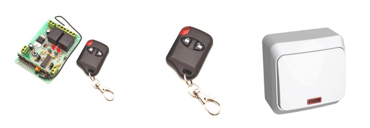
To solve our problem, the following was used:
The MP325M is a 433 MHz dual-channel wireless receiver, and the MP325M / transmitter is an optional two-channel transmitter in the form of a key fob. As you can see from the photo, the receiver comes without a case. On the receiver board there is a button for adding / removing key fobs and three LEDs. The green LED informs about pressing buttons on the remote control. Two red LEDs indicate the status of the ON / OFF relay. Two power relays have the ability to control loads with an operating voltage of 250 V and power up to 2000 watts. Relays have two operating modes: “Button” and “Trigger”. We will need the “Trigger” mode. The receiver is powered by 12 V.
The transmitter comes in a plastic case and is equipped with a quick-detachable snap hook for easy mounting, for example, on a bunch of car keys or the front door. On the transmitter housing there is a button press indicator, by which you can determine whether the battery needs to be replaced. The transmitter operates from a widespread 12 V type 27A battery and maintains operability up to a voltage of 6 V.
The range of the kit in direct line of sight is 100 meters, which is quite enough for home use. The transmitter communicates with the receiver using a digital signal having 1048576 code combinations, which is guaranteed to exclude false operation from interference and other transmitting devices at a given frequency. The kit turned out two transmitters. This is very helpful, since just two are needed to solve our problem.
You can use any adapter with a voltage of 12 V as a power source for the receiver. But I decided to take this seriously so that after a couple of months I won’t understand why the light does not turn on. A quality power source is the key to the reliable operation of the entire system. Therefore, PW1245 was acquired.
This source has excellent characteristics:
The source does not require soldering for connection - it has terminals for a screwdriver, which is convenient when mounted on a ladder.
What we do
First, it is advisable to de-energize the part of the circuit where we will make the modification. First of all, we remove the standard switch, and connect the two standard wires together, insulating them with PVC tape (if there is room, you can use the terminal block).

Then we take one of the transmitters and disassemble it. Parallel to one of the control buttons, solder two pieces of wire. We clean the resulting conclusions and connect to the contacts of the switch.

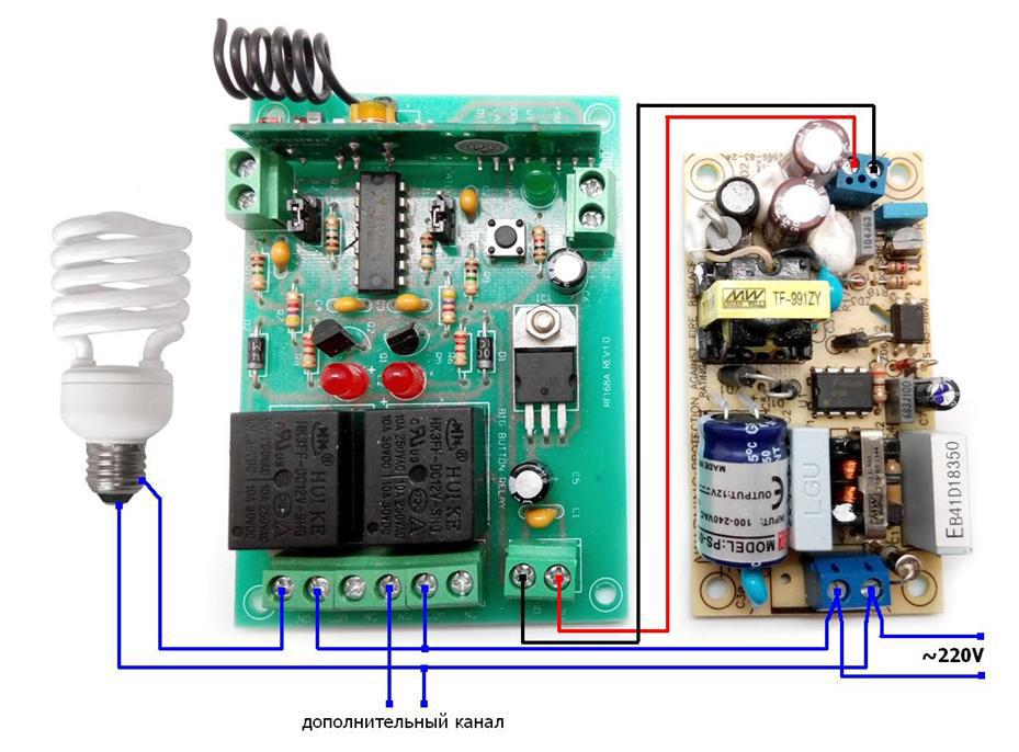
If desired, the transmitter’s handkerchief itself can also be wrapped with one layer of electrical tape (or in another way). Then go to the point of connection of the lamp or chandelier. We connect the modules according to the scheme below.
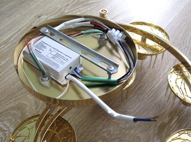
If the apartment has a suspended ceiling, the modules can be hidden in the space between the ceilings. If this is not possible, then you can try to install them in the niche of the connection lamp, previously insulating the receiver module and the power source with electrical tape.
Well, that’s all, you can use it.
Now you can independently control the lighting from the switch and remote control. If the switch stops working after a couple of years, do not panic, just replace the transmitter battery. The receiver can be powered from elements 27A or 23A, which are freely sold. The second channel can be used to turn on additional lighting, for example, the effect of the starry sky.

You can use both channels of the MP325M module. But this will require a two-button switch without locking. And the switch itself may have to be finalized by disconnecting the common bus in order to connect the second button of the MP325 remote control / transmitter. If necessary, a free relay can be used to control the receiver by connecting the COM and NC contacts in parallel with the reset / add remote control button.
Of course, each of us has its own living conditions, needs and opportunities. Perhaps someone will want to adapt our solution specifically for their needs, add additional features or offer their own option. To this we will happily say: Wellcome! Write! We are always happy with interesting ideas and are ready to translate them into reality!
A review of such systems showed that common solutions are applicable only to incandescent lamps, but are not suitable for energy-saving lamps. An attempt to adapt them also failed. After much deliberation and enumeration of the options, the MP325M system from Master Kit was chosen .
To solve our problem, the following was used:
- MP325M kit ;
- Power Supply PW1245 ;
- MP325M / transmitter ;
- One-button switch without locking (purchased on the construction market).
The MP325M is a 433 MHz dual-channel wireless receiver, and the MP325M / transmitter is an optional two-channel transmitter in the form of a key fob. As you can see from the photo, the receiver comes without a case. On the receiver board there is a button for adding / removing key fobs and three LEDs. The green LED informs about pressing buttons on the remote control. Two red LEDs indicate the status of the ON / OFF relay. Two power relays have the ability to control loads with an operating voltage of 250 V and power up to 2000 watts. Relays have two operating modes: “Button” and “Trigger”. We will need the “Trigger” mode. The receiver is powered by 12 V.
The transmitter comes in a plastic case and is equipped with a quick-detachable snap hook for easy mounting, for example, on a bunch of car keys or the front door. On the transmitter housing there is a button press indicator, by which you can determine whether the battery needs to be replaced. The transmitter operates from a widespread 12 V type 27A battery and maintains operability up to a voltage of 6 V.
The range of the kit in direct line of sight is 100 meters, which is quite enough for home use. The transmitter communicates with the receiver using a digital signal having 1048576 code combinations, which is guaranteed to exclude false operation from interference and other transmitting devices at a given frequency. The kit turned out two transmitters. This is very helpful, since just two are needed to solve our problem.
You can use any adapter with a voltage of 12 V as a power source for the receiver. But I decided to take this seriously so that after a couple of months I won’t understand why the light does not turn on. A quality power source is the key to the reliable operation of the entire system. Therefore, PW1245 was acquired.
This source has excellent characteristics:
- A wide range of input voltages from 90 to 260 V;
- Inrush current limitation, soft start;
- Protection complex: against short circuit, overload, overvoltage, overheating;
- Low leakage current.
The source does not require soldering for connection - it has terminals for a screwdriver, which is convenient when mounted on a ladder.
What we do
First, it is advisable to de-energize the part of the circuit where we will make the modification. First of all, we remove the standard switch, and connect the two standard wires together, insulating them with PVC tape (if there is room, you can use the terminal block).
Then we take one of the transmitters and disassemble it. Parallel to one of the control buttons, solder two pieces of wire. We clean the resulting conclusions and connect to the contacts of the switch.
If desired, the transmitter’s handkerchief itself can also be wrapped with one layer of electrical tape (or in another way). Then go to the point of connection of the lamp or chandelier. We connect the modules according to the scheme below.
If the apartment has a suspended ceiling, the modules can be hidden in the space between the ceilings. If this is not possible, then you can try to install them in the niche of the connection lamp, previously insulating the receiver module and the power source with electrical tape.
Well, that’s all, you can use it.
Now you can independently control the lighting from the switch and remote control. If the switch stops working after a couple of years, do not panic, just replace the transmitter battery. The receiver can be powered from elements 27A or 23A, which are freely sold. The second channel can be used to turn on additional lighting, for example, the effect of the starry sky.
You can use both channels of the MP325M module. But this will require a two-button switch without locking. And the switch itself may have to be finalized by disconnecting the common bus in order to connect the second button of the MP325 remote control / transmitter. If necessary, a free relay can be used to control the receiver by connecting the COM and NC contacts in parallel with the reset / add remote control button.
Of course, each of us has its own living conditions, needs and opportunities. Perhaps someone will want to adapt our solution specifically for their needs, add additional features or offer their own option. To this we will happily say: Wellcome! Write! We are always happy with interesting ideas and are ready to translate them into reality!