Our smart home lighting control devices
Hello!
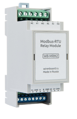
Almost a year ago, we first introduced our automation controller - Wiren Board Smart Home . Soon we will launch sales of its new version - Wiren Board 4 , and today we’ll talk about our two new devices from the class of budget wired peripherals for home automation.
To create a smart home one central controller can not do: some more actuators are required.
The Wiren Board controller was previously positioned as a universal smart home center that controls third-party actuators.
However, it became clear that for budget installations, the choice of peripherals is very limited, and the problem is especially acute, oddly enough, in the most common area of home automation - in lighting control.
1. What are the options?
Among the ready-made wireless devices for controlling the budget segment light, the choice consists of unidirectional (without feedback) devices operating at a frequency of 433 MHz:
- nooLite equipment (~ $ 20 per channel),
- Chinese noname kits (~ $ 10 per device),
- CoCo equipment (~ $ 20 per device), etc.
The lack of feedback, together with the use of the noisy order of the 433.92 MHz range, makes the use of these devices in home automation very inconvenient. The closest in price devices with feedback (Z-wave) are several times more expensive.
With wired devices, the situation is slightly better: in the budget segment there are devices based on Modbus or ADICON protocols, which are produced by several manufacturers: ICP-DAS, “Smart House”, Uniel. Many products of these manufacturers are successful, but in general, the price of devices and the price per channel in those executive devices that are not afraid to use are not as low as we would like. Some manufacturers do not work with retail customers, and few people always have them.
Seeing this sad situation, we decided to launch our line of wired peripherals.
As a test ball, we selected a dimmer for LED strips and a relay unit that operate according to the Modbus protocol, standard RS-485.
2. Why was Modbus chosen?
Modbus RTU is an open communication protocol based on the master-slave architecture. Widely used in industry. It is very easy to implement. RS-485 is a standard for transmitting data using a differential signal over a twisted pair cable of the “common bus” type, therefore the communication line is reliable and noise-resistant. The payback for this is the need for cable laying.
In home automation, the RS-485 is convenient in that it can be wired with a standard CAT5 twisted pair cable for Ethernet. In this case, one pair is used for data, two more - for power, one remains free. All devices are connected in parallel to one cable. Branches, “stars” and rings in the network topology are not allowed by the standard, but in practice even such networks work quite well at distances of tens of meters.
3. Local management
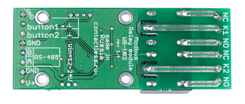
Modules are controlled both by Modbus and locally by connecting two external control buttons. This allows the modules to work completely autonomously. Therefore, by connecting a wall switch, you can control the lighting from it. This is convenient and generally increases the reliability of the entire system: in case of a central controller failure or an RS-485 bus break, the lighting continues to work normally - simply without automation.
Different modes of operation of the buttons are supported: switches without locking (most convenient), ordinary switches with locking.
Since the modules work in standalone mode, and almost all PLCs and controllers for home automation support the Modbus protocol, the modules can be laid during repair for future connection to a home automation system.
On modules, it is also possible to collect groups of passage switches, including using more than two switches connected in parallel. This will work even without a central controller.
4. Centralized management
The bus with the devices must be connected to the home automation controller for control. We developed devices for use with the Wiren Board controller, but there are no restrictions on the use of modules with other controllers that support Modbus RTU. A description of all registers is available on our wiki .
Each Modbus device on the bus must have a unique address, so the standard procedure for setting the address is the standard for installations on Modbus. The address is set by sending a broadcast write command to the appropriate register, and only one device should be connected to the port.
We tried to simplify the life of users in this place as much as possible, and we are distributing devices with predefined addresses that are written on the modules.
In addition to standard operations - setting the color for the LED dimmer and the state of the relay for the relay module - the devices have several other interesting features.
The relay module has a “Safety timer” function that allows you to turn off the relay if the module has not been interrogated by the central controller for a specified time. It is useful to use the function, for example, for controlling heaters in thermostats, when it is important that the load does not remain on in emergency situations, for example, when a bus breaks or when there are problems with the central controller.

Both devices allow the controller to read the current state of the buttons. Each button is also associated with a register counter, which stores the number of clicks on the corresponding button. This allows the use of buttons connected to devices in user rules.
All these functions are accessible through Modbus registers and are supported by the corresponding software on the Wiren Board (the code, as usual, is open and works on any Linux device).
In addition, the modules have several service blocks of registers. In one of these blocks, the model identifier is recorded, which allows automatic identification of devices on the bus. Another block contains the firmware version.
5. Design features of the modules:
The use of one-sided surface mounting allows you to make the modules quite compact and simple to manufacture. Chassis version (in heat shrink tube) significantly reduces the cost.
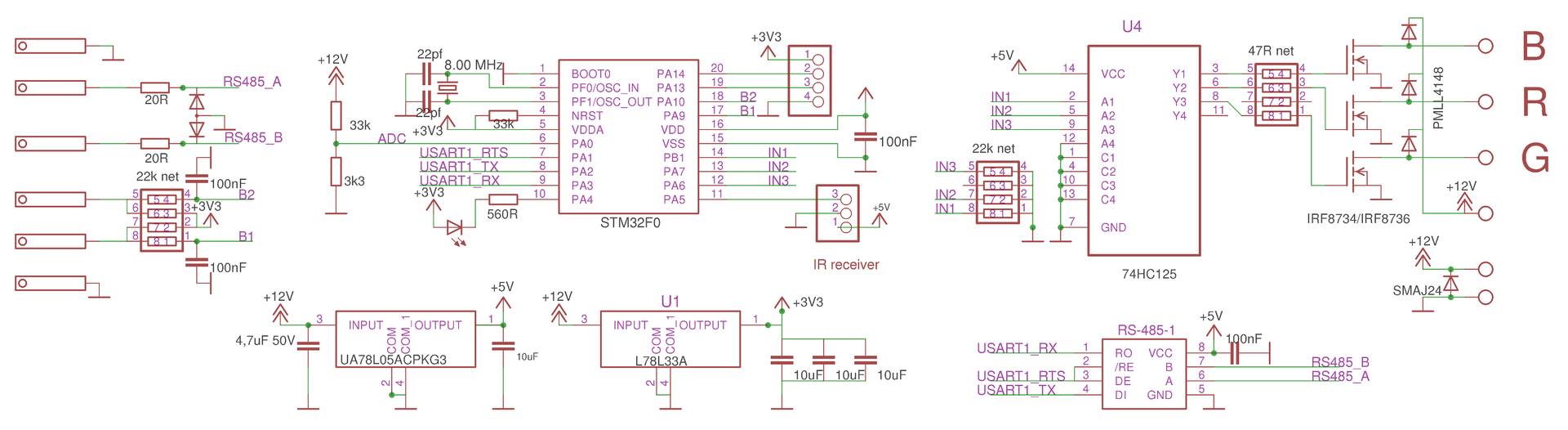
The brains of the modules are an inexpensive STM32F0 microcontroller, with a large margin of opportunity.
The consumption of the microcontroller and the RS-485 transceiver is quite small, which allows the use of linear regulators to power them. The operating voltage range of the modules is 8-24V .
Such a wide range of operating voltages is due to the lack of a single standard in home automation: in different systems both 12V and 24V are used. In addition, we wanted to ensure stable operation even when the voltage sags on the cables.
In order for the relay module to work in a wide voltage range, the following trick was used: the relays have an operating voltage of 12 volts, but the MK measures the input voltage and controls the relay coil using a PWM with a duty cycle of D = 12V / Uin, i.e. the average current through the relay coil remains nominal even at high input voltages. Also, after turning on the relay, the holding current is set to half of the rated current - this reduces the heating of the relay and the total device consumption by 4 times.
When using PWM, there is a feature: at low frequencies, the relays work like a speaker. To prevent the devices from beeping, the PWM frequency is taken out of the audio range and is 24 kHz.
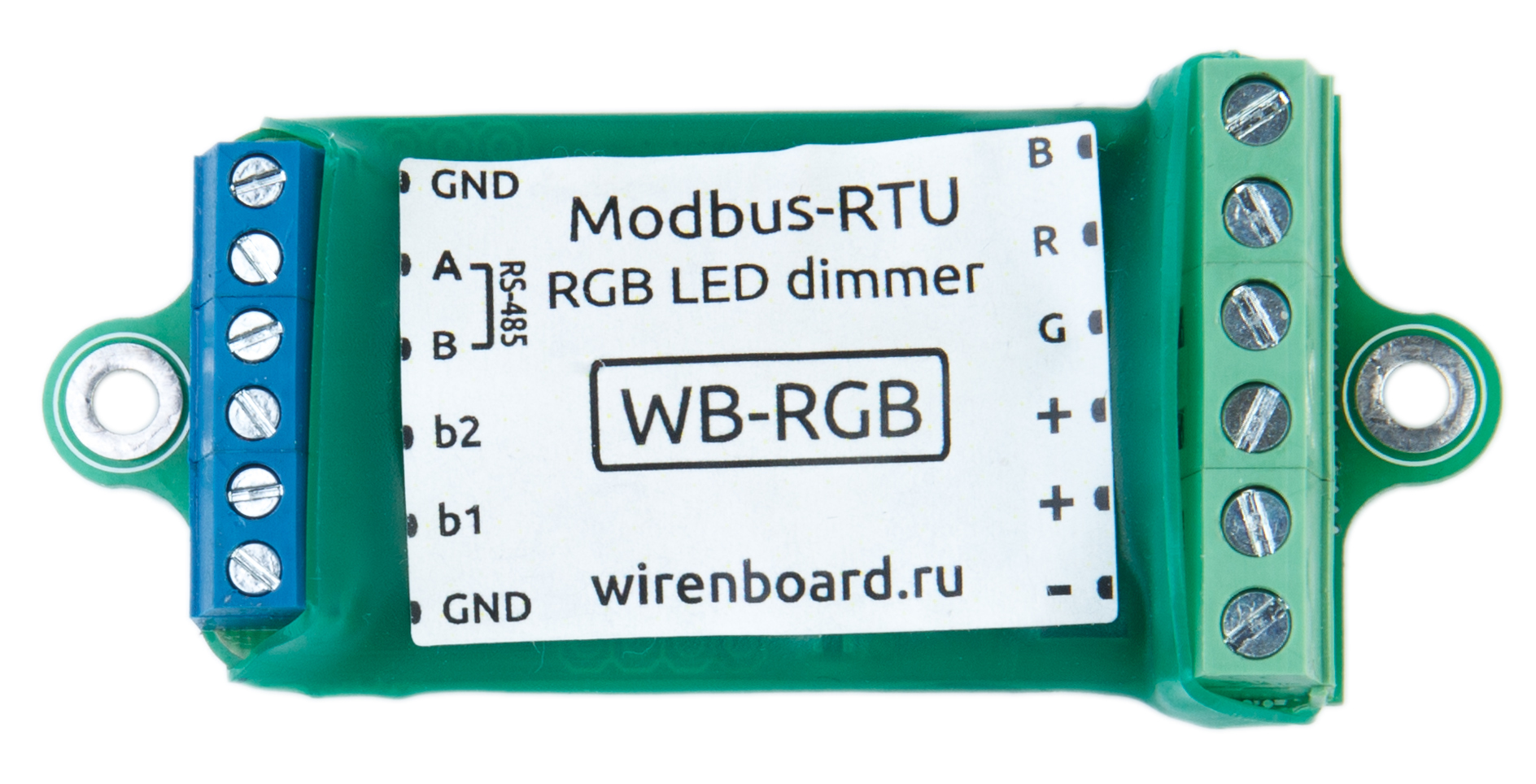
Power transistors LED dimmer WB-RGB - IRF8736 (Vmax = 30V, channel resistance of only ~ 5mOhm). Buffer 74HC125 increases the control voltage from 3.3V from MK to 5V at the gates. This allows such a small scarf to remain cold even at a current of 5A per channel.
To control the brightness of the LED strips in the LED dimmer, PWM is used. In the vast majority of competing products, the PWM frequency is in the region of 100-200 Hz, and in especially bad cases this leads to a noticeable flickering of lighting. In our device, PWM operates at a higher frequency. As in the case of the relay, the frequency is brought to the edge of the audio range, but here it is done to avoid the squeak of some not very high-quality power supplies of LED strips.
Obviously, the function of maintaining the state of the module when the power is turned off is highly desirable. STM32F0 has an unpleasant feature in this regard: it does not have a built-in EEPROM, only flash-memory with a very limited rewrite resource.
Writing to flash memory each time a new value is received is too wasteful, therefore the state is stored in RAM and is flushed to the flash only when the power fails. The moment of shutdown is monitored by the voltage drop below a certain threshold.
It is not enough to save the state at shutdown, because the number of overwrites per cell is limited to a thousand cycles. Therefore, the next level of optimization is to use all free memory, i.e. write values evenly using different cells.
The operation of writing a bit (i.e., setting a single value) to flash memory is quick, but erasing is performed only page by page, takes a lot of time and requires a lot of energy. If there are no free cells left, you need to erase the entire page before writing a new value. To do this, I would have to put a huge capacitor for "backup power" when turned off.
We use the following trick: when you turn on the MK, we first check the availability of free space for recording in flash, if it is not, then free up space for future recording by erasing pages.
6. Prices and plans
Since our main goal is to expand the ecosystem for Wiren Board controllers, we set fairly affordable prices for the new modules, which are lower than competing products:
- two-channel relay on a DIN rail WB-MR2-DIN costs 2000r
- the same two-channel shrink relay WB-MR2 - 1500r
- RGB-dimmer WB-MRGB: 2100 rubles .
We plan to expand the range of devices on Modbus, so we will be glad to receive feedback in the voting and in the comments about which modules you would like to see on sale.
Only registered users can participate in the survey. Please come in.
What else would we do
- 40.1% 8 Channel DIN Rail Relay Block 108
- 28.2% phase dimmer for incandescent lamps (and other dimmable lamps) 76
- 56.1% temperature and humidity sensor 151
- 44.6% light sensor 120
- 44.9% combustible gas sensor and CO 121
- 50.9% CO2 sensor 137
- 38.2% IR Transmitter for Air Conditioners / Televisions 103
- 36.4% module with dry contact inputs for meters and buttons 98