How to safely combine the network segments of the three major banks: share tricks
Some time ago, three large banks were merged under the VTB brand: VTB, ex-VTB24 and ex-Bank of Moscow. For external observers, the combined VTB Bank is now working as a single unit, but from the inside everything looks much more complicated. In this post we will talk about plans to create a unified network of the merged VTB bank, share live hacking on the organization of firewall interaction, docking and merging network segments without interrupting services.
VTB's current activities are supported by three legacy infrastructures: the ex-Bank of Moscow, the ex-VTB24, and the VTB itself. The infrastructures of each of them have their own set of network perimeters, on the border of which there are protection means. One of the conditions for the integration of infrastructures at the network level is the existence of a consistent IP addressing structure.
Immediately after the merge, we began the alignment of address spaces, and it is now coming to an end. But the process is laborious and slow, and the deadlines for organizing cross-access between infrastructures were very tough. Therefore, at the first stage, we connected the infrastructure of different banks to each other as they are - through firewalling in a number of main security zones. According to this scheme, in order to organize access from one network perimeter to another, it is necessary to pave the way for traffic through multiple firewalls and other means of protection, broadcast addresses of resources and users at the interfaces using NAT and PAT technologies. In this case, all firewalls at the interfaces are reserved both locally and geographically, and this must always be taken into account when organizing interactions and building service chains.
Such a scheme is quite efficient, but you can’t call it optimal. There are technical problems as well as organizational ones. It is necessary to coordinate and document the interactions of multiple systems, the components of which are scattered across different infrastructures and security zones. At the same time, in the process of transformation of infrastructures, it is necessary to quickly update this documentation for each system. Leading this process loads our most valuable resource - highly qualified specialists.
Technical problems are expressed in the multiplication of traffic on links, high load of protection tools, the complexity of the organization of network interactions, the inability to create some interactions without address translation.
The problem of traffic multiplication arises mainly due to the many security zones that interact with each other through firewalls at different sites. Regardless of the geographical location of the servers themselves, if the traffic goes beyond the perimeter of the security zone, it will pass through a chain of security tools that may be located in other locations. For example, we have two servers in one data center, but one is in the perimeter of VTB, and the other is in the perimeter of the ex-VTB24 network. The traffic between them does not go directly, but passes through 3-4 firewalls that may be active in other data centers, and traffic will be delivered to the firewall and back several times through the backbone network.
To ensure high reliability, we need every firewall in 3-4 instances - two on one site in the form of an HA cluster and one or two firewalls on another site, to which traffic will switch if the main firewall cluster or the site as a whole fails.
We summarize. Three independent networks are a whole heap of problems : excessive complexity, the need for additional expensive equipment, bottlenecks, redundancy difficulties and, as a result, high infrastructure maintenance costs.
Since we decided to take up the transformation of the network architecture, we will start with basic things. Let's go from the top down, let's start with an analysis of the requirements of business, applied, system engineers, security specialists.
Target network concept
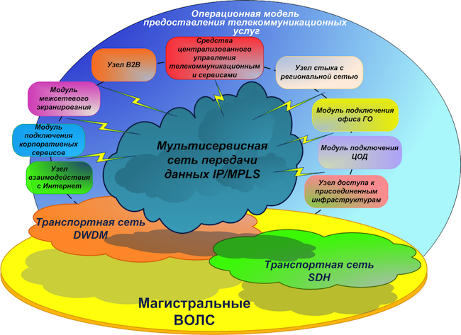
We will have a primary backbone network - a transport telecommunication infrastructure based on fiber-optic communication lines (FOCL), passive and active channel-forming equipment. It can also use the xWDM channel optical multiplexing subsystem and, possibly, an SDH network.
On the basis of the primary network, we are building a so-called backbone network . It will have a single address plan and a single set of routing protocols. The core network includes:
We create a multiservice network on a hierarchical basis with separation of transit (P) and terminal (PE) nodes . During the preliminary analysis of the equipment available on the market, it became clear that it would be more economically expedient to move the level of P-nodes to separate equipment than to combine the P / PE functionality in one device.
The multiservice network will have high availability, fault tolerance, minimal convergence time, scalability, high performance and functionality, in particular, support for IPv6 and multicast.
During the construction of the backbone network, we intend to abandon proprietary technologies.(where it is possible without deterioration), as we strive to make the solution flexible and not tied to a specific vendor. But at the same time, we don’t want to create a “vinaigrette” from equipment from various vendors. Our fundamental design principle is to provide the maximum number of services when using equipment with the minimum number of vendors for this. This will allow, among other things, to organize maintenance of the network infrastructure, employing a limited number of personnel. It is also important that the new equipment is compatible with existing equipment to ensure a seamless migration process.
The structure of the security zones of VTB, ex-VTB24 and ex-Bank of Moscow networks in the framework of the project is planned to be completely redesigned in order to merge functionally duplicated segments. A single structure of security zones is planned with common routing rules and a single concept of interconnect access. We plan to implement firewall between security zones using separate hardware firewalls, which are separated in two main locations. We also plan to implement all edge modules independently at two different sites with automatic backup between them based on standardized dynamic routing protocols.
We will manage the equipment of the core network through a separate physical network (out-of-band). Administrative access to all network equipment will be provided through a single authentication, authorization and accounting service (AAA).
To quickly find problems on the network, it is very important to be able to copy traffic from any point on the network for analysis and deliver it to the analyzer via an independent communication channel. To do this, we will create an isolated network for SPAN-traffic, with which we will collect, filter and transmit traffic flows to the analytics server.
To standardize the services provided by the network and the possibility of allocating expenses, we introduce a single catalog with SLA indicators. We turn to the service model, in which we take into account the interconnection of the network infrastructure with applied tasks, the interrelation of elements of control applications, and their influence on services. And this service model is supported by a network monitoring system so that we can allocate IT costs correctly.
Now let's go down to the level below and tell you about the most interesting solutions in our new infrastructure that may be useful to you.
We already familiarized with the resource forest of VTB . Now we will try to give a more detailed technical description.
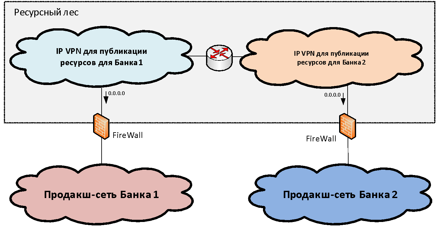
Suppose we have two (for simplicity) network infrastructures of different organizations that need to be combined. Within each infrastructure, as a rule, among the set of functional network segments (security zones), one can distinguish the main productive network segment where the main industrial systems are located. We connect these productive zones to a specific structure of lock segments, which we call the “resource forest” . In these gateway segments shared resources are available from two infrastructures.
The concept of a resource forest, from a network point of view, is to create a gateway security zone consisting of two IP VPNs (for the case of two banks). These IP VPNs are freely routed to each other and connected via firewalls to the productive segments. IP addressing for these segments is selected from a non-overlapping range of IP addresses. Thus, routing to the resource forest becomes possible from the networks of both organizations.
But with the routing from the resource forest towards the industrial segments, the situation is somewhat worse, since the addressing in them often overlaps and it is impossible to form a single table. To solve this problem, we just need two segments in the resource forest. In each of the resource forest segments, a default route was written in the direction of the industrial network of "its" organization. That is, users can access without translation of addresses to “their” segment of the resource forest and to another segment through PAT.
Thus, the two segments of the resource forest constitute a single gateway security zone, if we draw the border along firewalls. Each of them has its own routing: default gateway looks in the direction of "its" bank. If we place a resource in some segment of the resource forest, users of the respective bank can interact with it without NAT.
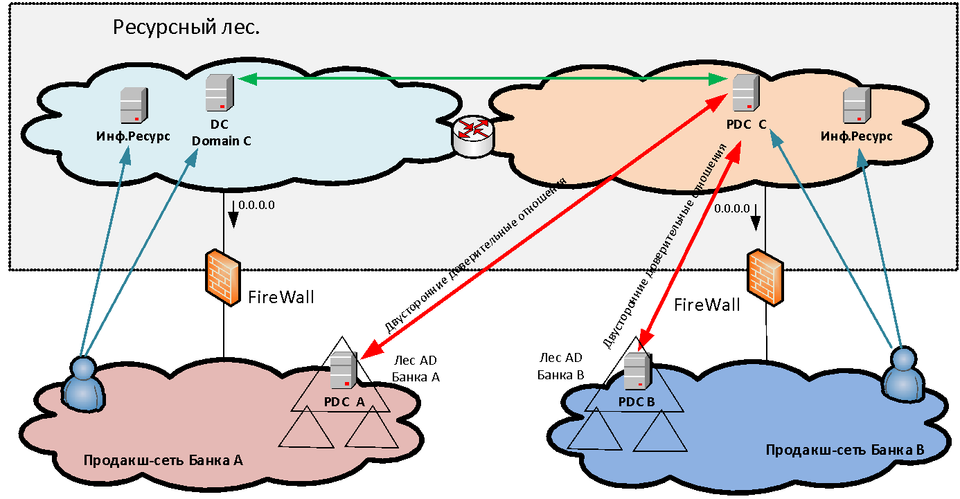
Interaction without NAT is very important for many systems and, first of all, for Microsoft domain interactions - after all, in the resource forest we have Active Directory servers for a new common domain, trusts with which are established by both organizations. Also, without a NAT-interaction, such systems as Skype for Business, the ABS system MBANK and many other diverse applications, where the server goes back to the client's address, require. And if the client is behind PAT, the reverse connection will not be established.
Servers that we install in resource forest segments are divided into two categories: infrastructure (for example, MS AD servers) and providing access to any information systems. The last type of servers we call data marts. Storefronts are, as a rule, web servers whose backend is already behind the firewall in the production network of the organization that created this storefront in the resource forest.
How user authentication is performedwhen accessing published resources? If we simply provide access to any applications for one or two users in another domain, then we can create separate accounts for them in our domain for authentication. But when we talk about a massive merger of infrastructures - say, 50 thousand users - it is completely unrealistic to start and accompany separate cross-registrations for them. Creating direct trusts between forests of different organizations is also not always possible both for security reasons and because of the need to make PAT users in the conditions of overlapping address spaces. Therefore, to solve the problem of unified user authentication, a new MS AD forest is created in the perimeter of the resource forest, consisting of one domain. In this new domain, users are authenticated when accessing services. To make this possible, bilateral forest-level trust relationships are established between the new forest and the domain forests of each organization. Thus, a user of any organization can authenticate to any published resource.
Once we have established the interaction of the systems through the infrastructure of the resource forest and thus removed the acute symptoms, it is time to take up the direct integration of networks.
To this end, at the first stage, we made the connection of the product segments of the three banks to a single powerful firewall (logically unified, but physically reserved many times on different sites). The firewall provides direct interaction between systems of different banks.
From the ex-VTB24, before organizing any direct interactions between the systems, we have already managed to align address spaces. Having formed routing tables on the firewall and opened the corresponding access, we were able to provide interaction between systems in two different infrastructures.
With the ex-Bank of Moscow, the address spaces at the time of the organization of applied interactions were not yet aligned, and we had to use mutual NAT to organize the interaction of the systems. The use of NAT has created a number of problems with a DNS resolver, which have been resolved by maintaining duplicate DNS zones. In addition, due to NAT, difficulties arose with the operation of a number of application systems. Now we have almost eliminated the intersection of address spaces, but we are faced with the fact that many systems of VTB and the ex-Bank of Moscow turned out to be tightly tied together to interact at the broadcast addresses. Now we need to migrate these interactions to real IP addresses while maintaining business continuity.
Here our goal is to ensure the operation of systems in a single address space for further integration of both infrastructure services (MS AD, DNS) and application services (Skype for Business, MBANK). Unfortunately, since part of the application systems are already tied to each other at the translated addresses, it requires individual work with each application system to eliminate NAT for specific interactions.
Sometimes you can do this trick.: set the same server at the same time and under the translated address, and under the real one. So application administrators can test the work at a real address before migration, try to switch to a non-NAT interaction themselves and roll back in case of anything. In this case, we are on the firewall using the packet capture function to monitor whether someone is communicating with the server via the translated address. As soon as such communication stops, we, in agreement with the owner of the resource, stop broadcasting: the server only has a real address.
After parsing the NAT, unfortunately, some time will have to keep the firewall between functionally identical segments, because not all zones meet the same security standards. After the segments are standardized, the firewall between the segments is replaced by routing and the functionally identical security zones are merged together.
Let us turn to the problem of internetwork firewalling. In principle, it is relevant for any large organization in which it is necessary to ensure both local and global fault tolerance of protection facilities.
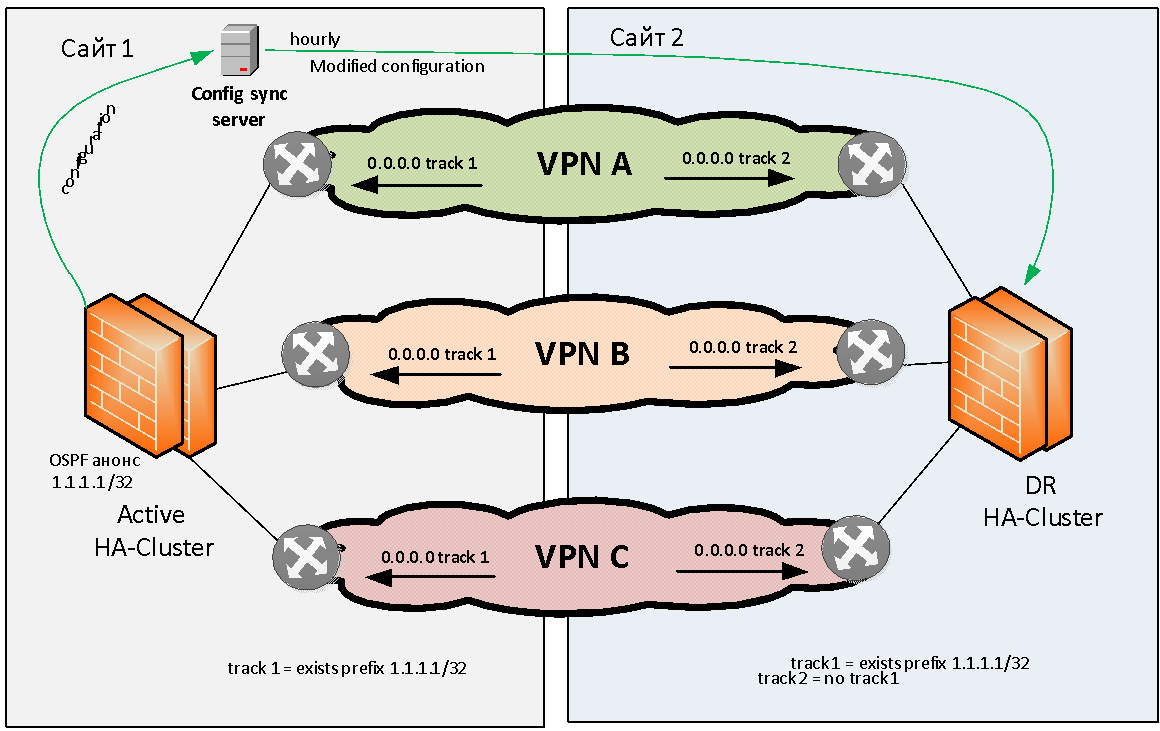
Let's try to formulate the problem of reserving firewalls in general. We have two sites: site 1 and site 2. There are several (for example, three) MPLS IP VPNs that interact with each other through a stateful firewall. This firewall is required to reserve locally and geographically.
We will not consider the problem of local backup of firewalls, almost any manufacturer provides the ability to assemble firewalls into a local HA cluster. As for the geographic redundancy of firewalls, almost no vendor has this task “out of the box” solved.
Of course, you can “stretch” a firewall cluster across several sites across L2, but then this cluster will be a single point of failure and the reliability of our solution will not be very high. Because clusters sometimes hang completely due to software errors, or fall into a state of split brain due to a broken L2 link between sites. Because of this, we immediately refused to stretch the firewall clusters on L2.
We needed to come up with a scheme in which, when a fire module failed, an automatic transition to another site would occur on one site. This is how we did it.
It was decided to adhere to the Active / Standby geo-reservation model when we have an active cluster on the same site. Otherwise, we immediately run into problems with asymmetric routing, which is difficult to solve with a large number of L3 VPNs.
An active firewall cluster must somehow signal its proper operation. As a signaling method, we chose OSPF announcement from the firewall to the network of the test (flag) route with the / 32 mask. The network equipment on site 1 tracks the presence of this route from the firewall and, if available, activates static routing (for example, 0.0.0.0 / 0), towards this firewall cluster. This static default route is then placed (via redistribution) in the MP BGP protocol table and distributed throughout the backbone network. When the main firewall cluster is live, it regularly broadcasts the flag route via OSPF, the routers monitor it, all routing is addressed to this firewall and all traffic flows to it over all IP VPN.
The backup site also tracks the presence of the flag path, but static routing towards the backup firewall cluster is configured inversely, that is, the traffic is sent to the backup firewall not if available but in the absence of a flag path from the main site.
If something happens to the firewall on site 1, the flag route disappears, the routers on site 1 remove the corresponding routes from the routing table, and the routers on site 2, on the contrary, raise the static routes towards the backup firewall. And after a while, depending on the convergence of the protocols, all traffic exchanged between VPNs goes to another site. For example, if one site is de-energized, default routes are automatically changed so as to enable the firewall on the working site.
As we described above, firewall clusters are reserved between sites under the active / standby scheme. All changes are made only to the active firewall. To synchronize the settings between the main and backup sites, we use a separate server that runs samopisny software. The software takes the settings, removes site-specific configuration parameters from them (for example, interface IP addresses and routing tables). And then loads the processed configuration into firewalls on other sites. This procedure is carried out automatically with a certain frequency. This scheme of firewalls allows you to achieve complete independence of the sites.
Many manufacturers have long promised to create a geographically distributed L3 firewall, but we have not yet met a solution that fully satisfies us. I had to do it myself.
Sometimes you need to organize a firewall between many of the same type of security zones. For example, there may be several dozen, if not more, in the case of, say, the use of test environments. If for each such security zone on the firewall to allocate a separate L3 interface, the infrastructure will not be very flexible and poorly scalable.
For such cases, we use a separate solution for organizing the service chain through a firewall, in which the firewall is connected to the network with just one IP interface. To feed traffic to this firewall, we use partially coupled MPLS VPN. We have one MPLS VPN "IN" and one VPN "OUT". Both of these VPNs are hubs in the HUB-and-spoke VPN topology. The Spoke feature of these HUBs is the same set of VPNs, between which you need to filter traffic.
The “IN” hub only exports the default route to the Spoke VPNs connected to it and does not import any routes from other VPNs. The “OUT” hub only imports routes from Spoke VPNs connected to it and does not export anything.
The firewall is enabled by its only interface in MPLS VPN "IN". The default in this VPN looks towards the firewall. Thus, all traffic flows by default from a set of VPNs to HUB-VPN "IN" and is sent to the firewall. The firewall filters traffic in accordance with global policies. Next, the firewall sends the filtered traffic back to the same single interface on which the return traffic is intercepted by the Policy Based Routing policies. They put this traffic in the VPN "OUT", from where it already spreads according to the full VPN "OUT" routing table into the necessary Spoke-VPN.
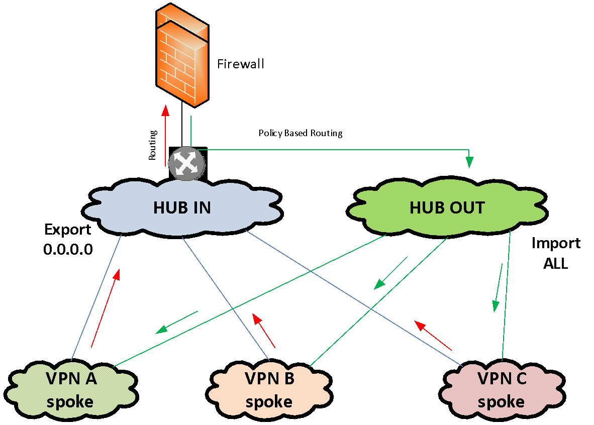
This scheme allows you to quickly combine a large number of VPNs that run through a single firewall. In fact, to connect a segment to the firewall, all you need to do is add the MPLS import / export records to the corresponding HUB VPNs.
In the classical scheme, each VPN connects to the firewall with a separate interface, which, taking into account multiple redundancy of firewalls, is not implemented quickly - it is necessary to allocate addressing for communication networks, VLAN numbering, provide routing, etc.
At the moment, we have provided the possibility of interaction between the systems of three united banks, connecting the networks along their perimeters, but the temporary scheme turned out to be not optimal from the point of view of operation. The project of networking is just beginning, and in the course of it we hope to build an optimal infrastructure, effective both in terms of capital costs and in terms of operation. In the next posts we will try to talk about other interesting solutions.
The complexity of the interaction of disparate infrastructures
VTB's current activities are supported by three legacy infrastructures: the ex-Bank of Moscow, the ex-VTB24, and the VTB itself. The infrastructures of each of them have their own set of network perimeters, on the border of which there are protection means. One of the conditions for the integration of infrastructures at the network level is the existence of a consistent IP addressing structure.
Immediately after the merge, we began the alignment of address spaces, and it is now coming to an end. But the process is laborious and slow, and the deadlines for organizing cross-access between infrastructures were very tough. Therefore, at the first stage, we connected the infrastructure of different banks to each other as they are - through firewalling in a number of main security zones. According to this scheme, in order to organize access from one network perimeter to another, it is necessary to pave the way for traffic through multiple firewalls and other means of protection, broadcast addresses of resources and users at the interfaces using NAT and PAT technologies. In this case, all firewalls at the interfaces are reserved both locally and geographically, and this must always be taken into account when organizing interactions and building service chains.
Such a scheme is quite efficient, but you can’t call it optimal. There are technical problems as well as organizational ones. It is necessary to coordinate and document the interactions of multiple systems, the components of which are scattered across different infrastructures and security zones. At the same time, in the process of transformation of infrastructures, it is necessary to quickly update this documentation for each system. Leading this process loads our most valuable resource - highly qualified specialists.
Technical problems are expressed in the multiplication of traffic on links, high load of protection tools, the complexity of the organization of network interactions, the inability to create some interactions without address translation.
The problem of traffic multiplication arises mainly due to the many security zones that interact with each other through firewalls at different sites. Regardless of the geographical location of the servers themselves, if the traffic goes beyond the perimeter of the security zone, it will pass through a chain of security tools that may be located in other locations. For example, we have two servers in one data center, but one is in the perimeter of VTB, and the other is in the perimeter of the ex-VTB24 network. The traffic between them does not go directly, but passes through 3-4 firewalls that may be active in other data centers, and traffic will be delivered to the firewall and back several times through the backbone network.
To ensure high reliability, we need every firewall in 3-4 instances - two on one site in the form of an HA cluster and one or two firewalls on another site, to which traffic will switch if the main firewall cluster or the site as a whole fails.
We summarize. Three independent networks are a whole heap of problems : excessive complexity, the need for additional expensive equipment, bottlenecks, redundancy difficulties and, as a result, high infrastructure maintenance costs.
General integration approach
Since we decided to take up the transformation of the network architecture, we will start with basic things. Let's go from the top down, let's start with an analysis of the requirements of business, applied, system engineers, security specialists.
- Based on their needs, we design the target structure of security zones and the principles of interconnection between these zones.
- We impose this structure of zones on the geography of our main consumers - data centers and large offices.
- Next, we form the transport MPLS network.
- Under it we are already bringing the primary network providing the services of the physical layer.
- Select the location of the location of the edge-modules and firewall modules.
- After the target picture is clarified, we work out and approve the method of migration from the existing infrastructure to the target one - so that the process is transparent for the operating systems.
Target network concept
We will have a primary backbone network - a transport telecommunication infrastructure based on fiber-optic communication lines (FOCL), passive and active channel-forming equipment. It can also use the xWDM channel optical multiplexing subsystem and, possibly, an SDH network.
On the basis of the primary network, we are building a so-called backbone network . It will have a single address plan and a single set of routing protocols. The core network includes:
- MPLS - multiservice network;
- DCI - links between data centers;
- EDGE-modules - various connection modules: firewalling, partner organizations, Internet channels, data centers, LANs, regional networks.
We create a multiservice network on a hierarchical basis with separation of transit (P) and terminal (PE) nodes . During the preliminary analysis of the equipment available on the market, it became clear that it would be more economically expedient to move the level of P-nodes to separate equipment than to combine the P / PE functionality in one device.
The multiservice network will have high availability, fault tolerance, minimal convergence time, scalability, high performance and functionality, in particular, support for IPv6 and multicast.
During the construction of the backbone network, we intend to abandon proprietary technologies.(where it is possible without deterioration), as we strive to make the solution flexible and not tied to a specific vendor. But at the same time, we don’t want to create a “vinaigrette” from equipment from various vendors. Our fundamental design principle is to provide the maximum number of services when using equipment with the minimum number of vendors for this. This will allow, among other things, to organize maintenance of the network infrastructure, employing a limited number of personnel. It is also important that the new equipment is compatible with existing equipment to ensure a seamless migration process.
The structure of the security zones of VTB, ex-VTB24 and ex-Bank of Moscow networks in the framework of the project is planned to be completely redesigned in order to merge functionally duplicated segments. A single structure of security zones is planned with common routing rules and a single concept of interconnect access. We plan to implement firewall between security zones using separate hardware firewalls, which are separated in two main locations. We also plan to implement all edge modules independently at two different sites with automatic backup between them based on standardized dynamic routing protocols.
We will manage the equipment of the core network through a separate physical network (out-of-band). Administrative access to all network equipment will be provided through a single authentication, authorization and accounting service (AAA).
To quickly find problems on the network, it is very important to be able to copy traffic from any point on the network for analysis and deliver it to the analyzer via an independent communication channel. To do this, we will create an isolated network for SPAN-traffic, with which we will collect, filter and transmit traffic flows to the analytics server.
To standardize the services provided by the network and the possibility of allocating expenses, we introduce a single catalog with SLA indicators. We turn to the service model, in which we take into account the interconnection of the network infrastructure with applied tasks, the interrelation of elements of control applications, and their influence on services. And this service model is supported by a network monitoring system so that we can allocate IT costs correctly.
From theory to practice
Now let's go down to the level below and tell you about the most interesting solutions in our new infrastructure that may be useful to you.
Resource forest: details
We already familiarized with the resource forest of VTB . Now we will try to give a more detailed technical description.
Suppose we have two (for simplicity) network infrastructures of different organizations that need to be combined. Within each infrastructure, as a rule, among the set of functional network segments (security zones), one can distinguish the main productive network segment where the main industrial systems are located. We connect these productive zones to a specific structure of lock segments, which we call the “resource forest” . In these gateway segments shared resources are available from two infrastructures.
The concept of a resource forest, from a network point of view, is to create a gateway security zone consisting of two IP VPNs (for the case of two banks). These IP VPNs are freely routed to each other and connected via firewalls to the productive segments. IP addressing for these segments is selected from a non-overlapping range of IP addresses. Thus, routing to the resource forest becomes possible from the networks of both organizations.
But with the routing from the resource forest towards the industrial segments, the situation is somewhat worse, since the addressing in them often overlaps and it is impossible to form a single table. To solve this problem, we just need two segments in the resource forest. In each of the resource forest segments, a default route was written in the direction of the industrial network of "its" organization. That is, users can access without translation of addresses to “their” segment of the resource forest and to another segment through PAT.
Thus, the two segments of the resource forest constitute a single gateway security zone, if we draw the border along firewalls. Each of them has its own routing: default gateway looks in the direction of "its" bank. If we place a resource in some segment of the resource forest, users of the respective bank can interact with it without NAT.
Interaction without NAT is very important for many systems and, first of all, for Microsoft domain interactions - after all, in the resource forest we have Active Directory servers for a new common domain, trusts with which are established by both organizations. Also, without a NAT-interaction, such systems as Skype for Business, the ABS system MBANK and many other diverse applications, where the server goes back to the client's address, require. And if the client is behind PAT, the reverse connection will not be established.
Servers that we install in resource forest segments are divided into two categories: infrastructure (for example, MS AD servers) and providing access to any information systems. The last type of servers we call data marts. Storefronts are, as a rule, web servers whose backend is already behind the firewall in the production network of the organization that created this storefront in the resource forest.
How user authentication is performedwhen accessing published resources? If we simply provide access to any applications for one or two users in another domain, then we can create separate accounts for them in our domain for authentication. But when we talk about a massive merger of infrastructures - say, 50 thousand users - it is completely unrealistic to start and accompany separate cross-registrations for them. Creating direct trusts between forests of different organizations is also not always possible both for security reasons and because of the need to make PAT users in the conditions of overlapping address spaces. Therefore, to solve the problem of unified user authentication, a new MS AD forest is created in the perimeter of the resource forest, consisting of one domain. In this new domain, users are authenticated when accessing services. To make this possible, bilateral forest-level trust relationships are established between the new forest and the domain forests of each organization. Thus, a user of any organization can authenticate to any published resource.
Getting Network Integration
Once we have established the interaction of the systems through the infrastructure of the resource forest and thus removed the acute symptoms, it is time to take up the direct integration of networks.
To this end, at the first stage, we made the connection of the product segments of the three banks to a single powerful firewall (logically unified, but physically reserved many times on different sites). The firewall provides direct interaction between systems of different banks.
From the ex-VTB24, before organizing any direct interactions between the systems, we have already managed to align address spaces. Having formed routing tables on the firewall and opened the corresponding access, we were able to provide interaction between systems in two different infrastructures.
With the ex-Bank of Moscow, the address spaces at the time of the organization of applied interactions were not yet aligned, and we had to use mutual NAT to organize the interaction of the systems. The use of NAT has created a number of problems with a DNS resolver, which have been resolved by maintaining duplicate DNS zones. In addition, due to NAT, difficulties arose with the operation of a number of application systems. Now we have almost eliminated the intersection of address spaces, but we are faced with the fact that many systems of VTB and the ex-Bank of Moscow turned out to be tightly tied together to interact at the broadcast addresses. Now we need to migrate these interactions to real IP addresses while maintaining business continuity.
NAT abolition
Here our goal is to ensure the operation of systems in a single address space for further integration of both infrastructure services (MS AD, DNS) and application services (Skype for Business, MBANK). Unfortunately, since part of the application systems are already tied to each other at the translated addresses, it requires individual work with each application system to eliminate NAT for specific interactions.
Sometimes you can do this trick.: set the same server at the same time and under the translated address, and under the real one. So application administrators can test the work at a real address before migration, try to switch to a non-NAT interaction themselves and roll back in case of anything. In this case, we are on the firewall using the packet capture function to monitor whether someone is communicating with the server via the translated address. As soon as such communication stops, we, in agreement with the owner of the resource, stop broadcasting: the server only has a real address.
After parsing the NAT, unfortunately, some time will have to keep the firewall between functionally identical segments, because not all zones meet the same security standards. After the segments are standardized, the firewall between the segments is replaced by routing and the functionally identical security zones are merged together.
Firewall internetworking
Let us turn to the problem of internetwork firewalling. In principle, it is relevant for any large organization in which it is necessary to ensure both local and global fault tolerance of protection facilities.
Let's try to formulate the problem of reserving firewalls in general. We have two sites: site 1 and site 2. There are several (for example, three) MPLS IP VPNs that interact with each other through a stateful firewall. This firewall is required to reserve locally and geographically.
We will not consider the problem of local backup of firewalls, almost any manufacturer provides the ability to assemble firewalls into a local HA cluster. As for the geographic redundancy of firewalls, almost no vendor has this task “out of the box” solved.
Of course, you can “stretch” a firewall cluster across several sites across L2, but then this cluster will be a single point of failure and the reliability of our solution will not be very high. Because clusters sometimes hang completely due to software errors, or fall into a state of split brain due to a broken L2 link between sites. Because of this, we immediately refused to stretch the firewall clusters on L2.
We needed to come up with a scheme in which, when a fire module failed, an automatic transition to another site would occur on one site. This is how we did it.
It was decided to adhere to the Active / Standby geo-reservation model when we have an active cluster on the same site. Otherwise, we immediately run into problems with asymmetric routing, which is difficult to solve with a large number of L3 VPNs.
An active firewall cluster must somehow signal its proper operation. As a signaling method, we chose OSPF announcement from the firewall to the network of the test (flag) route with the / 32 mask. The network equipment on site 1 tracks the presence of this route from the firewall and, if available, activates static routing (for example, 0.0.0.0 / 0), towards this firewall cluster. This static default route is then placed (via redistribution) in the MP BGP protocol table and distributed throughout the backbone network. When the main firewall cluster is live, it regularly broadcasts the flag route via OSPF, the routers monitor it, all routing is addressed to this firewall and all traffic flows to it over all IP VPN.
The backup site also tracks the presence of the flag path, but static routing towards the backup firewall cluster is configured inversely, that is, the traffic is sent to the backup firewall not if available but in the absence of a flag path from the main site.
If something happens to the firewall on site 1, the flag route disappears, the routers on site 1 remove the corresponding routes from the routing table, and the routers on site 2, on the contrary, raise the static routes towards the backup firewall. And after a while, depending on the convergence of the protocols, all traffic exchanged between VPNs goes to another site. For example, if one site is de-energized, default routes are automatically changed so as to enable the firewall on the working site.
As we described above, firewall clusters are reserved between sites under the active / standby scheme. All changes are made only to the active firewall. To synchronize the settings between the main and backup sites, we use a separate server that runs samopisny software. The software takes the settings, removes site-specific configuration parameters from them (for example, interface IP addresses and routing tables). And then loads the processed configuration into firewalls on other sites. This procedure is carried out automatically with a certain frequency. This scheme of firewalls allows you to achieve complete independence of the sites.
Many manufacturers have long promised to create a geographically distributed L3 firewall, but we have not yet met a solution that fully satisfies us. I had to do it myself.
One legged firewall
Sometimes you need to organize a firewall between many of the same type of security zones. For example, there may be several dozen, if not more, in the case of, say, the use of test environments. If for each such security zone on the firewall to allocate a separate L3 interface, the infrastructure will not be very flexible and poorly scalable.
For such cases, we use a separate solution for organizing the service chain through a firewall, in which the firewall is connected to the network with just one IP interface. To feed traffic to this firewall, we use partially coupled MPLS VPN. We have one MPLS VPN "IN" and one VPN "OUT". Both of these VPNs are hubs in the HUB-and-spoke VPN topology. The Spoke feature of these HUBs is the same set of VPNs, between which you need to filter traffic.
The “IN” hub only exports the default route to the Spoke VPNs connected to it and does not import any routes from other VPNs. The “OUT” hub only imports routes from Spoke VPNs connected to it and does not export anything.
The firewall is enabled by its only interface in MPLS VPN "IN". The default in this VPN looks towards the firewall. Thus, all traffic flows by default from a set of VPNs to HUB-VPN "IN" and is sent to the firewall. The firewall filters traffic in accordance with global policies. Next, the firewall sends the filtered traffic back to the same single interface on which the return traffic is intercepted by the Policy Based Routing policies. They put this traffic in the VPN "OUT", from where it already spreads according to the full VPN "OUT" routing table into the necessary Spoke-VPN.
This scheme allows you to quickly combine a large number of VPNs that run through a single firewall. In fact, to connect a segment to the firewall, all you need to do is add the MPLS import / export records to the corresponding HUB VPNs.
In the classical scheme, each VPN connects to the firewall with a separate interface, which, taking into account multiple redundancy of firewalls, is not implemented quickly - it is necessary to allocate addressing for communication networks, VLAN numbering, provide routing, etc.
Conclusion
At the moment, we have provided the possibility of interaction between the systems of three united banks, connecting the networks along their perimeters, but the temporary scheme turned out to be not optimal from the point of view of operation. The project of networking is just beginning, and in the course of it we hope to build an optimal infrastructure, effective both in terms of capital costs and in terms of operation. In the next posts we will try to talk about other interesting solutions.