Reverse Engineering ESP8266 - Part 2
- Tutorial
We are continuing the study of the ESP8266 module. This time, consider the process of downloading firmware for disassembly.
The first part of the article is here .
Having prepared the necessary tools, we came to the most interesting part - downloading and disassembling the firmware.
Let's start with the simplest - downloading the app.out file - firmware in the ELF format created using the SDK.
Typically, the app.out file is available when you have the source code for the firmware, which is much easier and more logical to learn. However, to get acquainted with the features of the compiler, the location of segments and see the names of functions, I suggest starting with it.
After compilation and assembly, the app.out file will appear in the build folder, which is the compiled user code, data, libraries, and debugging information. In this form, the firmware cannot be loaded into the module, therefore, after assembling the ELF file, the SDK converts app.out into one or two files in the firmware folder - 0x00000.bin and 0x40000.bin, which can be directly flashed.
Opening app.out in HIEW and looking at the segment table (enter, F8, F6) we will see the following picture:
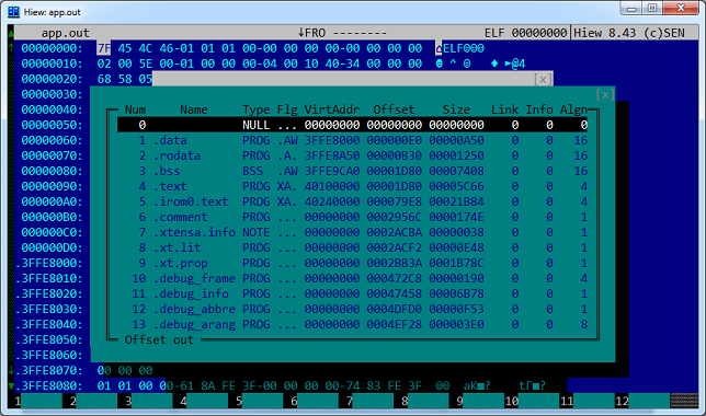
The VirtAddr column contains the addresses of the start of segments in the Xtensa address space. Please note that three segments (.data, .rodata and .bss) will be loaded into the RAM area, the .text segment will be written to the address of the user executable code, and the .irom0.text segment will be written to the address of the SDK library code. The remaining segments with a starting address of zero contain service information and will not be added to the firmware ready for uploading to the module.
Looking ahead, I will say that the .irom0.text segment will be copied to the 0x40000 file in its original form, and the .data, .rodata, .bss and .text segments will be assembled into the 0x00000.bin file, taking into account the format that was discussed above.
To load app.out into the IDA, do the following:
1. Open IDA Pro 6.6 or higher
2. Click “Go” - we won’t open any files yet
3. Open the File - Script file menu item and select the xtensa.py processor definition script
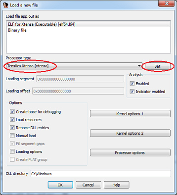
4. Download the app.out file, here you need to select the processor type and click “Set”:
5. In the following windows with a warning about an unknown type of machine and offers to download debugging information, click “Yes”
6. As a result, we get a file ready for investigation:
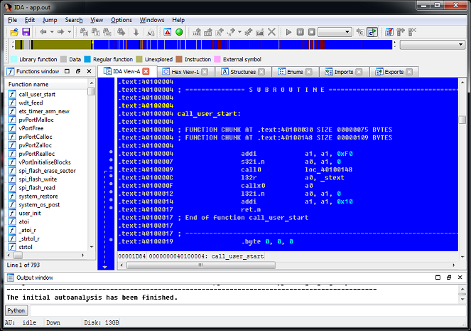
What is missing in it? There is not enough system ROM containing the basic functions of the module. If necessary, it can be downloaded manually, which we will do in the next section.
We looked at a fairly simple firmware download in the IDA as an ELF file. However, in practice, it is often required to study ready-made firmware extracted from the flash module (by connecting to flash directly) or distributed as 0x00000.bin and 0x40000.bin files. Here you will have to do a little handmade work. Let's start by loading the system ROM image. In the first part, I gave a link to the archive with the file 40000000.bin - this is it. The sequence of actions is as follows:
1. Open IDA Pro 6.6 or higher
2. Press “Go”
3. Open the File - Script file menu item and select the xtensa.py processor definition script
4. Open the 40000000.bin file
5. Select the Tensilica Xtensa processor type [ xtensa] and click "Set"
6. Next, you need to specify the memory organization for the correct download of the binary file. Here we create a code segment at 0x40000000 and load our file into it:
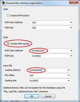
7. The ROM image is loaded, but it is poorly read due to the lack of function names. Now load the script 40000000.idc, which will do the extra work - it will determine the names of the functions and create additional segments in the address space: File - Script file - 40000000.idc. Here is the result:
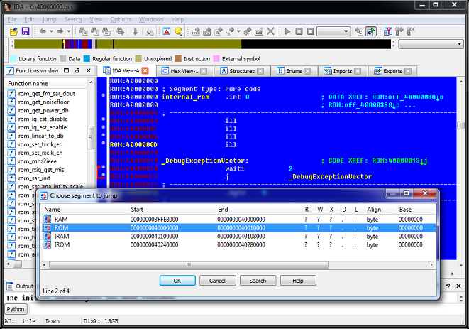
On this, the boot of the system ROM can be considered completed, you can proceed to its study. The script determined the names of the functions of the system ROM, now you can figure out what this or that function is called from the SDK.
And here, by the way, is a function that copies user firmware from flash to SoC memory:
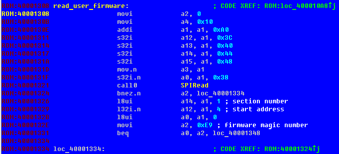
There is no such function in the SDK, so I gave it a name arbitrary.
But the firmware is not complete without loading the user part - the files 0x00000.bin and 0x40000.bin. Therefore, upload these files to the system ROM.
We loaded the system ROM module into the IDA, and the script prepared several segments for us to load the remaining parts. Let's start with a simple one - loading library code.
As I said above, the firmware file 0x40000.bin is an image of a code segment without any service information and is directly mapped to the address space of the processor at 0x40240000. To load it into the IDA, we will do the following:
1. Make sure that we have an open database 40000000.bin and the script 40000000.idc has created additional segments: RAM, ROM, IRAM, IROM
2. Select File - Load file - Additional binary file from the menu , open the firmware file 40000.bin
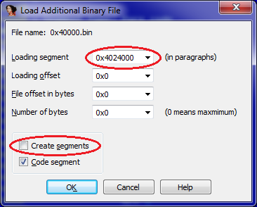
3. In the next window, select the boot options. Please note that loading is done by offset in paragraphs, i.e. instead of the address, we indicate the value 10h times less (discard the last zero). A daw for creating a segment can be removed, it has already been created:
4. The file is uploaded. After indicating the beginning of the code (in this case, 4024000Ch), we get about the following picture:
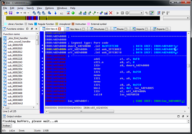
Unlike an ELF file, the names of functions and variables will not be defined here, but there is nothing to be done about it.
Now go to the file 00000.bin. We remember that this is not just an image, but a file with a structure that describes data and code segments. This is how it might look when viewed in hexadecimal:
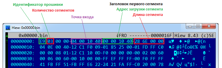
First comes 8 bytes of the general firmware header, which determines the number of segments and the entry point. Then the segments themselves go, also having 8 byte headers with address and length.
To load them correctly in the IDA, I cut out the data of each segment (without headers) into separate files, naming them at the download address:
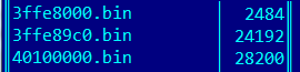
Now it remains to load them in the IDA. For each file, we perform a sequence of actions similar to loading the system ROM:
1. File - Load file - Additional binary file, select the data file
2. In the download parameters, specify the segment (by file name without the last zero), we do not create a segment.
That's all, now we have a fully loaded and ready for research firmware!
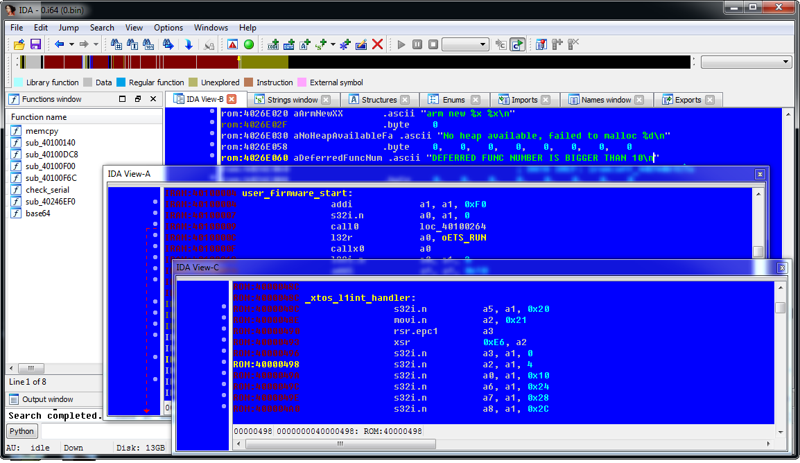
In this part of the article, we looked at loading procedures for various types of ESP8266 firmware for disassembling in IDA Pro. In the final part, we will consider the features of the Xtensa processor, differences from the x86 architecture, a set of registers and commands.
The first part of the article is here .
Content
- Introduction
- Architecture ESP8266
- Memory card (address space)
- Firmware format
- Launch process
- Instruments
- Download firmware for research
- ELF
- Module firmware
- Custom firmware
- Assembler Xtensa
- Registers
- Basic operators
- Functions
- Conditional jumps
- Conclusion
- References
4. Download firmware for research
Having prepared the necessary tools, we came to the most interesting part - downloading and disassembling the firmware.
ELF
Let's start with the simplest - downloading the app.out file - firmware in the ELF format created using the SDK.
Typically, the app.out file is available when you have the source code for the firmware, which is much easier and more logical to learn. However, to get acquainted with the features of the compiler, the location of segments and see the names of functions, I suggest starting with it.
After compilation and assembly, the app.out file will appear in the build folder, which is the compiled user code, data, libraries, and debugging information. In this form, the firmware cannot be loaded into the module, therefore, after assembling the ELF file, the SDK converts app.out into one or two files in the firmware folder - 0x00000.bin and 0x40000.bin, which can be directly flashed.
Opening app.out in HIEW and looking at the segment table (enter, F8, F6) we will see the following picture:
The VirtAddr column contains the addresses of the start of segments in the Xtensa address space. Please note that three segments (.data, .rodata and .bss) will be loaded into the RAM area, the .text segment will be written to the address of the user executable code, and the .irom0.text segment will be written to the address of the SDK library code. The remaining segments with a starting address of zero contain service information and will not be added to the firmware ready for uploading to the module.
Looking ahead, I will say that the .irom0.text segment will be copied to the 0x40000 file in its original form, and the .data, .rodata, .bss and .text segments will be assembled into the 0x00000.bin file, taking into account the format that was discussed above.
To load app.out into the IDA, do the following:
1. Open IDA Pro 6.6 or higher
2. Click “Go” - we won’t open any files yet
3. Open the File - Script file menu item and select the xtensa.py processor definition script
4. Download the app.out file, here you need to select the processor type and click “Set”:
5. In the following windows with a warning about an unknown type of machine and offers to download debugging information, click “Yes”
6. As a result, we get a file ready for investigation:
What is missing in it? There is not enough system ROM containing the basic functions of the module. If necessary, it can be downloaded manually, which we will do in the next section.
Module firmware
We looked at a fairly simple firmware download in the IDA as an ELF file. However, in practice, it is often required to study ready-made firmware extracted from the flash module (by connecting to flash directly) or distributed as 0x00000.bin and 0x40000.bin files. Here you will have to do a little handmade work. Let's start by loading the system ROM image. In the first part, I gave a link to the archive with the file 40000000.bin - this is it. The sequence of actions is as follows:
1. Open IDA Pro 6.6 or higher
2. Press “Go”
3. Open the File - Script file menu item and select the xtensa.py processor definition script
4. Open the 40000000.bin file
5. Select the Tensilica Xtensa processor type [ xtensa] and click "Set"
6. Next, you need to specify the memory organization for the correct download of the binary file. Here we create a code segment at 0x40000000 and load our file into it:
7. The ROM image is loaded, but it is poorly read due to the lack of function names. Now load the script 40000000.idc, which will do the extra work - it will determine the names of the functions and create additional segments in the address space: File - Script file - 40000000.idc. Here is the result:
On this, the boot of the system ROM can be considered completed, you can proceed to its study. The script determined the names of the functions of the system ROM, now you can figure out what this or that function is called from the SDK.
And here, by the way, is a function that copies user firmware from flash to SoC memory:
There is no such function in the SDK, so I gave it a name arbitrary.
But the firmware is not complete without loading the user part - the files 0x00000.bin and 0x40000.bin. Therefore, upload these files to the system ROM.
Custom firmware
We loaded the system ROM module into the IDA, and the script prepared several segments for us to load the remaining parts. Let's start with a simple one - loading library code.
As I said above, the firmware file 0x40000.bin is an image of a code segment without any service information and is directly mapped to the address space of the processor at 0x40240000. To load it into the IDA, we will do the following:
1. Make sure that we have an open database 40000000.bin and the script 40000000.idc has created additional segments: RAM, ROM, IRAM, IROM
2. Select File - Load file - Additional binary file from the menu , open the firmware file 40000.bin
3. In the next window, select the boot options. Please note that loading is done by offset in paragraphs, i.e. instead of the address, we indicate the value 10h times less (discard the last zero). A daw for creating a segment can be removed, it has already been created:
4. The file is uploaded. After indicating the beginning of the code (in this case, 4024000Ch), we get about the following picture:
Unlike an ELF file, the names of functions and variables will not be defined here, but there is nothing to be done about it.
A slight digression
How to examine bare assembler code? How to understand what this or that function performs? For many well-known SDKs, the IDA has FLIRT signatures that define the names of standard functions. In our case, this will not help, since the IDA does not know this SDK. So this work will have to be done manually. As an example, I will give several methods in increasing order of complexity:
1. Find the signature of the function under study in the disassembler of an ELF file compiled with the same version of the SDK. There is a possibility that you will find her, and she will have a name (from the debug information). Including for this I was considering downloading firmware to ELF.
2. Known constants - the function can refer to text strings or binary data. With experience, you remember many such constants by heart, if the constant is unfamiliar - google. Here is an example:
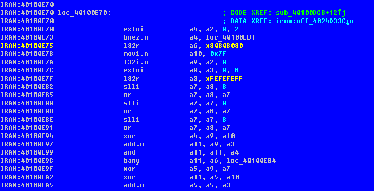
We see two noteworthy constants. Google gives the first link a description of the strlen algorithm using these constants:

Comparing the implementations of the algorithm, we can say with confidence that the strlen function is located at 40100E70h.
Or here is a piece of code that immediately produces a division function:

3. Actually, the study of assembler code and an attempt to understand what the function performs. Sometimes it can be determined that we have a “local” implementation of a familiar algorithm, and sometimes not.
In any case, the skill of understanding assembly code comes with experience, so go for it!
1. Find the signature of the function under study in the disassembler of an ELF file compiled with the same version of the SDK. There is a possibility that you will find her, and she will have a name (from the debug information). Including for this I was considering downloading firmware to ELF.
2. Known constants - the function can refer to text strings or binary data. With experience, you remember many such constants by heart, if the constant is unfamiliar - google. Here is an example:
We see two noteworthy constants. Google gives the first link a description of the strlen algorithm using these constants:
Comparing the implementations of the algorithm, we can say with confidence that the strlen function is located at 40100E70h.
Or here is a piece of code that immediately produces a division function:
3. Actually, the study of assembler code and an attempt to understand what the function performs. Sometimes it can be determined that we have a “local” implementation of a familiar algorithm, and sometimes not.
In any case, the skill of understanding assembly code comes with experience, so go for it!
Now go to the file 00000.bin. We remember that this is not just an image, but a file with a structure that describes data and code segments. This is how it might look when viewed in hexadecimal:
First comes 8 bytes of the general firmware header, which determines the number of segments and the entry point. Then the segments themselves go, also having 8 byte headers with address and length.
To load them correctly in the IDA, I cut out the data of each segment (without headers) into separate files, naming them at the download address:
Now it remains to load them in the IDA. For each file, we perform a sequence of actions similar to loading the system ROM:
1. File - Load file - Additional binary file, select the data file
2. In the download parameters, specify the segment (by file name without the last zero), we do not create a segment.
That's all, now we have a fully loaded and ready for research firmware!
In this part of the article, we looked at loading procedures for various types of ESP8266 firmware for disassembling in IDA Pro. In the final part, we will consider the features of the Xtensa processor, differences from the x86 architecture, a set of registers and commands.