Enhanced Two-Player Reaction Game on ATmega32: From Prototype to Production Build
Embedded systems developers often start with simple prototypes on the ATmega328P, but for scaling up, they move to more powerful microcontrollers like the ATmega32. The second iteration of this two-player reaction trainer uses exactly that: it increases the number of indicators, adds animations, and scores up to three wins. Soldering is done with flux paste, and the board requires post-processing for cleanliness—optimal methods include isopropyl alcohol with an ultrasonic bath or specialized flux cleaners.
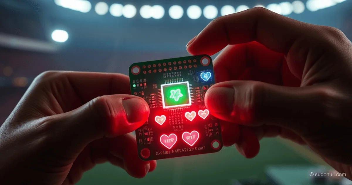
The keychain geometry is kept compact for pocket carry. On the front side, there's silkscreen with hearts as score indicators; on the back, the project logo.
Visualization and Hardware
Each player gets three LEDs under their button: blue for the first, red for the second. A central green LED signals the start. The schematic is available in the project's Gerber files, and 3D visualization confirms the ergonomics.


Game Logic and Firmware
The game implements a reaction to a visual stimulus with randomized delay. The firmware on the ATmega32 controls:
- A blinking green LED for preparation.
- Detection of the first button press.
- Animation of blinking LEDs at the end of a round.
- A win counter up to three.
Rules in pseudocode:
while (game_not_started) { blink(green_LED, random_delay); }delay(random(100-500ms)); light(green_LED);if (button1_press < button2_press) { score1++; animation(blue_LEDs); } else { score2++; animation(red_LEDs); }if (score1 == 3 || score2 == 3) { final_animation(); reset(); }
Firmware is optimized for low power consumption, with AVR timers ensuring accurate delays without blocking.
Version Comparison
| Parameter | Version 1 (ATmega328P) | Version 2 (ATmega32) |
|-----------|------------------------|----------------------|
| LEDs per player | 1 | 3 |
| Scoring | Up to 1 | Up to 3 |
| Animation | None | Blinking effects |
| Silkscreen | None | Full (hearts, logo) |
| Soldering | Basic | Paste + flux |
Moving to the ATmega32 provided more pins for expansion, 32 KB Flash compared to 32 KB on the 328P, but with better peripherals.
Assembly Recommendations
- Use 0.5 mm solder paste for SMD components.
- After soldering: clean in an ultrasonic bath with 99% isopropyl alcohol for 5–10 minutes.
- Test timings with an oscilloscope: the delay should be uniform random.
- For firmware: avrdude with USBasp, fuse bits for 16 MHz internal oscillator.
Expansion: add a buzzer for audio feedback or Bluetooth for scores in an app.
Key Takeaways
- Scaling the prototype: Going from one LED to three with animation increases engagement without complicating the circuit.
- ATmega32 advantages: More GPIO, UART for debugging, suitable for multi-player.
- SMD soldering: Flux cleaning is critical for longevity; avoid no-clean without post-processing.
- Reaction timings: Random delay of 100–500 ms mimics real-world scenarios.
- Firmware structure: Non-blocking loops on timers for responsiveness.
— Editorial Team










No comments yet.