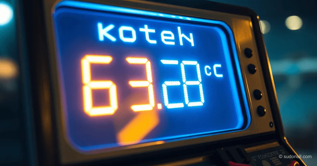
Vintage Cash Register Display in a Smart Home: Integration with ESP8266 and MQTT
Vintage gas discharge displays from cash registers are perfect material for creating compact information panels in smart home systems. This article details the adaptation of the Wincor Nixdorf BA64-2 display for control via ESP8266 with NTP synchronization and MQTT interface integration. The solution allows displaying critically important data without constant access to the main interface.
Hardware Analysis and Pinout
The Wincor Nixdorf BA64-2 display is a two-line gas discharge indicator (20×2 characters) in a compact housing. The key challenge is the lack of documentation for the non-standard RJ45 connector. Initial inspection revealed the following features:
- The connector is physically compatible with Ethernet but electrically non-compliant
- Supports two interfaces: USB and RS232 via a single connector
- No pin markings in the datasheet
After disassembling the device and analyzing the board with a voltmeter, the pinout was determined:
- Pin 1: +5V (power)
- Pin 4: GND
- Pins 2-3: USB Data±
- Pins 6-8: RS232 signals (TxD/RxD)
It's critically important to check voltages with a multimeter before connecting, as standard adapters can damage the device. An oscilloscope confirmed RS232 levels (-7/+7V) on pins 6 and 8.
Modification for Direct TTL-Serial Connection
The ADM3232E chip—a TTL-RS232 converter—was found on the board. Removing it provides access to the native TTL-Serial interface, simplifying integration with modern controllers. The steps are:
- Desolder the chip using a hot air gun at 350°C
- Clean the contact pads of solder residue
- Identify the R2out/T2in lines (main transmission channel)
- Connect wires to the pads: VCC (3.3V), GND, TX, RX
- Secure the connections with hot glue
Direct TTL-Serial connection eliminates the need for level shifters. Note: the display operates on 3.3V, so power must match. For stable operation, a 4 ms delay is required between transmitted bytes—this compensates for the display's low data processing speed.
Example data handling:
bool outs = false;
void outString(char * buf, int length){
  if(outs) return;
  outs = true;
  for(int i=0; i< length; i++){
    Serial.write(buf[i]);
    delay(4);
  }
  outs = false;
}
Software Implementation and Integration
The firmware, based on the Arduino Framework, implements three key functions: Wi-Fi connection, MQTT client, and NTP synchronization. The architecture includes:
- Automatic switching between modes (clock/info message)
- Handling of escape sequences for cursor control
- UTF-8 character support (including °C)
Main code components:
#define CLEAR_SCREEN "\x1B[2J"
#define LINE1_0 "\x1B[1;0H"
#define INFO_PERIOD 60000

void drawClock(){
  time_t dtm = time(nullptr) + 10800; // UTC+3
  DateTime now = DateTime(dtm);
  char buf[21];
  sprintf(buf, "\x1B[1;0H%02d.%02d.%04d %02d:%02d:%02d",
    now.day(), now.month(), now.year(),
    now.hour(), now.minute(), now.second());
  outString(buf, strlen(buf));
}

void msg_callback(char* topic, byte* payload, unsigned int length){
  if(!strncmp((char *)payload, "line1 ", 6)){
    clock_mode = false;
    info_timer = millis();
    outString(LINE1_0, strlen(LINE1_0));
    outString((char*)&payload[6], length - 6);
  }
}
Time synchronization is handled via a local NTP server. At startup, the system waits up to 4 seconds for time acquisition:
void TimeSetup(){
  configTime(0, 0, "ntpserver.home");
  int cnt = 4;
  while (!time(nullptr) && cnt > 0) {
    delay(1000);
    cnt--;
  }
}
Info message mode automatically ends after 60 seconds, returning to clock display. This prevents blocking the main interface.
Practical Application in Smart Home Systems
Integrating the display into existing ecosystems addresses two key needs:
- Real-time monitoring of critical parameters — boiler temperature, basement humidity, solar panel status
- Notifications without a smartphone — system messages ("Gas leak", "Gate open")
Example for tracking temperature:
mosquitto_pub -h localhost -t "ba64/line1" -m "kotel 63.28/55.43\xC2\xB0C"The system is scalable: multiple displays can show different information by subscribing to specific topics. To extend functionality, simply modify the MQTT message handler to support new commands.
Key Points
- Voltage checks are mandatory: measure all pins before connecting—standard adapters can damage the display.
- Transmission delay is critical: without delay(4) between bytes, data loss occurs due to processing speed differences.
- OTA updates are a must: retain the ability to reflash without physical access to the device.
- Escape sequences: use control codes from the datasheet for precise cursor positioning.
- Local NTP server: external servers may be unavailable, disrupting clock operation.
— Editorial Team








No comments yet.