Boring weekend or "car for pumping"
 Some time ago, I said: " Tuning" a car is personally somehow not interesting for me personally ... ", but" never say "never". " The stars got up in such an order that they had to urgently change the Peugeot 307sw to Mazda5.
 The car drives, everything is fine, but some of the "buns" that were in the previous car regularly, for some reason, were missing in the current one.
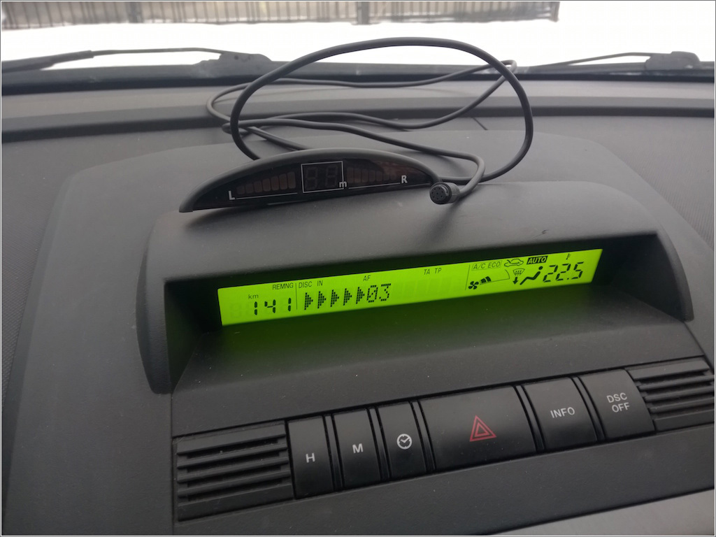
One of these useful things is parking sensors. Installation of parking sensors is not a problem, but somehow the "step-by-step" display of parking sensors in the cabin did not suit me. The internal perfectionist was terribly against the "alien body."
Googled for some time and found out that, it turns out, several years ago, a friend from St. Petersburg made a special “add-on,” which, on the one hand, was connected to the parking sensors, and on the other, to the car. And while the information from the parking sensors was displayed on a standard display.
Even a video was found
It would seem that you need to buy, put and relax, but that project “died”, the author does not get in touch: you can’t buy.
But this is not our method ... if you can’t buy it, then you can “reinvent it” (and upgrade your skills in programming microcontrollers).
Part One: Parktronic
At first it was necessary to choose parking sensors. The original project used Parkmaster (a model that was already completely inaccessible - discontinued). I had to choose from what can be freely purchased. The choice fell on Parkmaster 4-DJ-06 (the same brand - it was hoped that "someone already picked it up, so I can too," but compared with the original model - "increased detection speed of obstacles, improved stability, sensors new design with efficient water drainage, etc. ”).
The first thing that was done was the disassembled display and studied the connection of the cable to it. It turned out that the display is connected with 5 wires: GND, + 5V, DATA, CS, CLK. Those familiar with the SPI bus, immediately notice some similarities (in the parking sensors DATA = MOSI). The connection of the display with the main unit is one-way (the main unit is master, the display is slave), so one conductor (MISO) is not enough for a "full" SPI.
Connecting an oscilloscope fully confirmed this hypothesis:
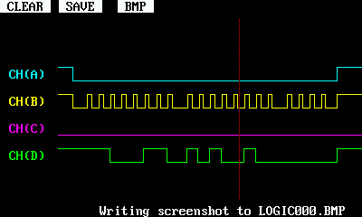
Channel A - CS, B - CLK, D - DATA.
Further, it was a technical matter: it was necessary to figure out how to “remove” all code messages and decode what was transmitted there.
We have already talked about reverse engineering the protocol of another parking sensors , so I won’t describe it like that, I’ll just give a link to the forum thread where the “truth was born” for my particular case (there is also a code with the help of which the code messages were “captured”. My nickname on that forum is ustas).
The work was rather routine, but in order to do everything “beautifully and interestingly” I used two interruptions. The first interrupt followed CS, the second followed CLK. There was nothing particularly interesting in this part.
A couple of days off, several evenings, and I had a ready-made prototype on a breadboard (with arduino-nano), which confidently received data from the main unit of the parking sensors and decoded them. The choice of parking sensors was justified - even the levels did not have to be agreed.
After that, parking sensors were installed in the car and the main development site moved there.
Part Two: Listening
At the same time I learned a lot about the fact that almost all modern machines are to a large extent “computers” on wheels, even a “network of computers”: since almost all more or less “smart” units are connected to a single CAN bus and “communicate” with it between themselves".
In general, two buses are usually present in cars: HS-CAN and MS-CAN (high-speed and medium-speed bus, respectively). The first relates mainly to the operation of the engine and related systems, the second - it is also called the "comfort tire" - refers to various service functions (music system, "tidy", lighting, climate, doors, etc.).
In my car, the display is just connected to the MS-bus - this bus has become the "target" for my project. Of course, additional information is needed. Manufacturers, of course, possess all the necessary information, but are in no hurry to share it (although the situation is beginning to change , but not in my case).
The starting point was this page , on which some message identifiers are presented and what data is encoded in these messages. The comments on this post also found useful notes.
Before sending something to the bus, I decided that I should first “listen” to my car and make sure that the information presented is true.
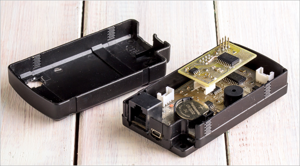
Since there was no suitable shield with the CAN interface at hand, I had to abandon the “arduins” (and anyway I decided to make the appropriate device for installation in the car) - I parted a simple board that contained the MK (atmega328p), the CAN bus controller (MCP2515 / MCP2551), tweeter ... and ... clock module.
What do not collect on avr, but in the end you still get hours
from amateur radio forums
Well, who would have thought that the machine that was produced in this millennium has a watch, but no calendar? Since I am still a sclerotic, I decided that the calendar would definitely not hurt me, so the DS1307 also “registered” on the device’s board.
The device diagram does not shine at all with some originality: typical schemes for including all components (from their datasheets) are used. Just in case, I brought almost all the available I / O ports to an additional connector (suddenly something else comes to mind during the implementation?). Naturally, for the programmer, I spread ICSP.
It was decided to take power from a USB charge, so the board has a miniUSB connector. I laid an additional cable from the Parktronic unit (during installation), which “duplicates” the main cable between the display and the Parktronic (so that you can simultaneously connect both a standard Parktronic display and my “product”). The cable came first caught ... You are not very surprised to learn that it turned out to be a long patchcord? Therefore, the board has a corresponding connector (black, left). The form of the board was dictated by the existing case.
Eagle, LUT, ferric chloride and further down the list ...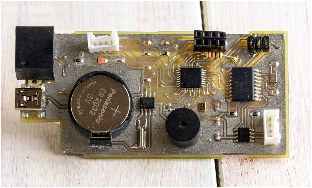
At the first stage, I decided (for simplicity) to connect to the diagnostic connector, since the MS bus is present in it. Where exactly in the connector should I look, spied here .
With the hardware, I hope everything is clear ... move on to the software. I used a ready-made library to work with the CAN bus . Test cases helped a lot - they made it possible to start “listening” almost immediately. The only thing that had to be corrected was to indicate in the sketch the correct MS bus speed (CAN_125KBPS).
Data on where to look for display messages was completely confirmed (for verification, I turned on the head unit in the radio mode and selected a radio station that displayed only its name through RDS and then found the corresponding packages). There were two packages in which this name was encoded (in the first package - the first 7 characters, in the second - the remaining 5 characters).
Part Three: Talking
The first attempts to send messages to the display failed. The standard car display simply ignored my packages.
In order to deal with this problem (and for convenience) - at the “disassembly” I purchased a display from Mazda3 (a much more common spare part than a similar one from Mazda5). The most noticeable difference between the displays is the color of the backlight (Mazda5 is green, Mazda3 is red). The rest is almost identical and I hoped that the differences were only "cosmetic" (and I was right).
I assembled a small test bench at home, consisting of my device and this display. Testing at the stand is much more comfortable than in a car, outdoors in winter.
In parallel, I found a wonderful comment:
You can send the 3 frames with the following IDs:
0x28F: LCD settings and probably some other other settings (you just send the same data you receive in a normal 0x28f frame).
0 × 290: 0xC0 (first byte) followed by first 5 alfanum signs
0 × 291: 0 × 85 (first byte) followed by the next 7 alfanum signs
all of them, just after you receive the 0 × 291 frame id sent by the Hu. This will make your text being visible with almost no flicker at all.
The reason for sending the 0x28F is that it is required for displaying the 0 × 290 and 0 × 291 text, otherwise the LCD seems to simply ignore the 0 × 290 and 0 × 291.
Another method would be to set a timer with a 150ms interrupt and send the 3 frames described above.
...
0x28F frame content that I have used:
hex: D1 00 00 00 80 00 00 01
Thus, in order for the display to display the transmitted text, three messages must be transmitted (during the first tests I transmitted only two, and because of this the display refused to display my text).
But for some reason at home on the stand and the correct sequence did not work out - the display remained empty. I got into the car: the same code - worked perfectly. He began to understand and realized that for the test bench there was not enough 120 ohm resistor on the bus (between CAN-H and CAN-L). As soon as I put this resistor, the display came to life.
Part Four: Logic
I am very careful about various kinds of “tuning” and I think that if you do it, it’s only in such a way that it looks like “full-time functionality”.
Observing the operation of the standard display suggested the logic that I wanted to implement: as soon as the display does not change for more than 5 seconds, you can display “your” information (for example, date), but if “the car wants to say something” (new information ) - immediately remove the "abnormal" message and display information from the machine.
Naturally, it is impossible to comply with such logic when parking, in this case only information from the parking sensors should be displayed).
At home, I wrote the bulk of the code, everything looked more or less decent on the test display. But after a visit to the car, serious got out ...
Part Five: The Rake
The problem was that the head unit “floods” the bus with its messages to the display with a period of about once every 150ms (even if the information on the display did not change). This led to the fact that "abnormal" messages almost immediately "frayed" regular.
Then began the "
The approach would probably work on a faster MK, but the atmega’s speed wasn’t enough - regular messages “skipped” periodically and this led to a “mess” of messages that was very unpleasant for the eye (especially considering that the text was transmitted in two portions: sometimes a situation arose that the first part of the message is from the car, and the second is from my module).
In general, it works, but not at all as we would like.
To solve this problem, it was necessary to somehow "tear" too "talkative" radio from the bus.
One could put a “relay” that would disconnect the radio from the CAN bus at the time of displaying abnormal information, but this would violate the logic (for example, I would start to change the volume, while the message “VOL 7” with the corresponding level and this message would be skipped).
Those. It was necessary to solve the problem: listen to the CAN bus, analyze messages and send the necessary messages to the display.
“A correctly asked question is half the answer.” I came up with the need to add a second CAN interface. At the same time, my device is turned on “in the cut” of the CAN bus between the machine and the display. The device “listens” to what the machine reports (and generally takes everything it needs from the bus), data analysis is carried out, and only the necessary information is transmitted to the display.
In order not to completely redo the board, I did a “shield” (the diluted additional I / O and ICSP ports came in handy), because the CAN bus controller is connected to the MK via the SPI bus.
This is the result of such a device:
For convenience, ICSP was made “pass-through” so that it was not necessary to disassemble the “sandwich” each time for updating the firmware.
Part Six: Tests
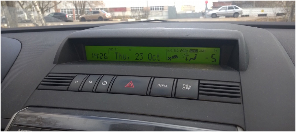
At home, my prototype only “took” data from the PDR, but nothing was done to “visualize” the result. As soon as the main problems with the device have been eliminated and the connection diagram has already been “fixed”, I recreated the operation of the parking sensors display on a standard display. It turned out like this:
The video shows that the output is almost identical, and in some cases, information appears on the Mazda display a split second earlier (which is not bad at all).
After the main parts of the firmware were debugged, I decided to install my development in the machine in order to arrange a serious test operation.
And then the following problem was discovered:
The information of the climate control unit (the right side of the display) was missing. As it turned out, this is not the only loss - the trip computer also refused to show its information.
This was not a big surprise, because in the firmware I “followed” only messages on the central part of the display (received, analyzed and, if necessary, displayed on the display), all other messages were simply ignored.
Obviously, it was necessary to find message identifiers that contained the “missing” information. It did not take much time.
The following identifiers were found
- 0x38A compulsory sending, without it the minibus does not work
- 0x400 route data
- 0x3BA climate
- 0x201 current parameters (speed, revolutions)
After the rules for the direct broadcast of messages with these identifiers to the display were added to the firmware code, everything worked as it should.
Part seven: "... and galloped!"
In the process of searching for various information, I registered on the Mazda5 owners forum - shared my best practices, showed how it turns out. It turned out that this project is interesting not only to me. At the conference they helped to search for the necessary information, suggested possible functions.
During the discussion, it turned out that not all trim levels have a trip computer, but replacing the display with another one adds this function. This indicated that the data is on the bus, and the display function was implemented in some models, but not in others (moreover, this is implemented in the display firmware).
I checked this hypothesis and made sure that it is correct. It was quite simple to isolate the following data:
- average speed,
- instant fuel consumption
- average fuel consumption
- power reserve on the remaining fuel.
“Dug” a little deeper - also found current data: speed, engine speed.
In general, the data search process needs to be described in more detail - this may seem interesting (and useful for such reverse engineering).
The first look at this problem is frightening: there are many messages with different identifiers on the bus and it is quite difficult to track which one has changed. But it turned out that with the proper approach, the task can be greatly simplified. I did the following (for example, when searching for data on the status of the parking brake):
In the course of such studies of messages, I found out that the tire has information about the condition of all the doors of the car, parking brake, turn signals, etc.
- included logging of all messages (so that the amount of data for analysis was not too large - limited the time interval to 5-10 seconds),
- in the time allotted for the test, the handbrake raised and lowered,
- the received data was uploaded to Excel,
- included "autofilter",
- found the identifier of messages where the data changed (during such "atomic" actions, one bit usually changed),
- allocated such message identifiers (usually such an identifier was one),
- included “filtering” in the firmware (so that only “interesting” messages were recorded),
- repeated analysis with filtered data.
In the course of such studies of messages, I found out that the tire has information about the condition of all the doors of the car, parking brake, turn signals, etc.
Once the data is there, you need to use it somehow.
Immediately I added to my module the notification function for open doors at speeds above 10 km / h.
Yes, the dashboard has a full-time indicator of open doors, but it only signals this fact, but does not specify which door is not closed.
Then I remembered that Peugeot had a standard function of automatically locking doors at speed. Obviously, here you can add the same function too ... but not on the prototype (unfortunately, control of the central lock in Mazda is not possible via the CAN bus, although in some other machines this is quite realistic).
Thus, the list of functions has expanded somewhat:
- parking sensors,
- the calendar,
- output of the trip computer data,
- open door control
- auto-locking of doors at speed,
- auto-mute music when parking (to better hear the "squeaker" parking sensors),
- voltage control of the onboard network.
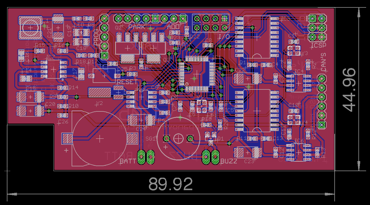
Since the result of my work was interesting for the confectioners — I decided to completely redo the device circuit (making it “single-board” and “self-sufficient”): I turned on all the necessary interfaces, powerful transistor switches, and a DC / DC power converter. At the same time, he made a board of its original size:
Naturally, all the knowledge gained was useful in the process of creating and operating the prototype (the same 120 Ohm resistor in the CAN bus for the display to work).
It turned out that all the connections to the wiring of the machine could be made directly behind the display (there is a very large empty niche and all the necessary signal wires are present).
As a “protection”, I made additional platforms for connecting an “alternative” backup battery for the clock module (suddenly, in the winter, the CR1225 backup battery will “freeze” and the clock will go astray) and an external “tweeter”.
Part Eight: Production
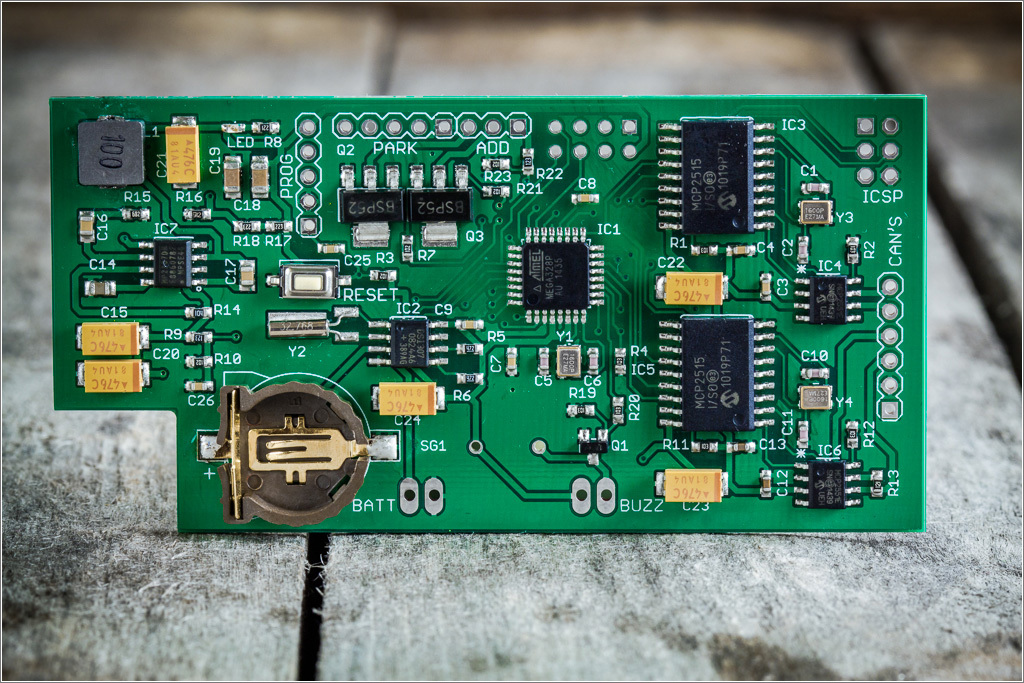
The board turned out to be quite compact due to the fact that it switched to frame size 0603 (in the prototype it was 0805), quite a few vias (although it optimized tracing many times), tracks / clearances - 0.2mm. In principle, it was possible to make LUT at home, but the project already took too much of my time, I decided that it would be much easier for someone to pay so that the board was made in the right amount and the components were unzipped (there were 9 interested confectioners, plus for my car instead of the prototype).
I already had a similar experience of ordering in the “Celestial Empire” - I entrusted it to “my” contractor. It turned out relatively budget (cheaper than just buying accessories in Moscow stores), but not too much (a small batch). He made payment for the production with funds raised from those who wished (“micro-crowdfunding”).
The devices were not produced very quickly - it took almost 3 weeks. But the post office has increased the waiting period by almost a month. But let's not talk about sad things, since it turned out pretty well:
On the reverse side of the board is nothing interesting: micro-instructions for connecting.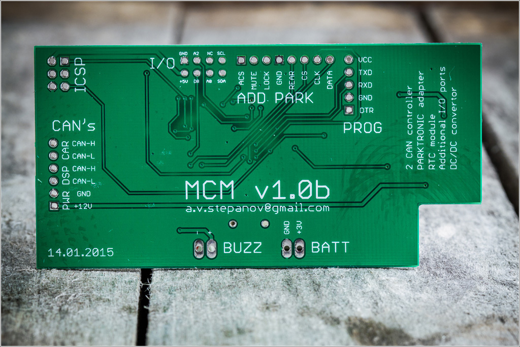
Replacing the prototype with a "factory" product took me about half an hour (while the process was also photographed to make it easier for users). But not everything went smoothly: the auto-mute function of music on my particular radio did not work (the frugal Japanese, unfortunately, did not solder the System Mute circuit). But the management of door locks worked right away (though after a fairly thorough study of the car wiring diagram and the search for the “same” wire that is responsible for locking).
Part Nine: Settings
Due to the fact that the device must be installed in machines of different configurations (and for different users), it was necessary to figure out how to implement the configuration mode (enable / disable the necessary messages, functions, setting the date / time). Of course, “for myself” I would not even think about this task at all - there is nothing easier than connecting a programmer, but not in this case. You need to think about the "consumers" of the device.
At the same time, according to the “Logic” part, everything should look as standard as possible and without adding additional buttons to the cabin (even a hidden installation). And then I successfully remembered that you can easily get data on the status of doors, parking brake, “turn signals”, and, in the latter, the state in the bus completely repeated the state of the lamps (the corresponding bit in the package “blinked”).
He entered the settings mode according to the “shamanic” sequence: on a standing car (zero current speed), the driver's door must be opened (we monitor its condition) and within 15 seconds from the moment the doors are opened, raise and lower the parking brake three times. Then, “SETUP?” Appears on the display. and to confirm - close the driver's door. Those. "Nonrandom" sequence of actions (which it is unlikely that someone will accidentally reproduce the car in normal operation).
Navigate through the “settings menu” using the steering column switch for direction indicators: left - down, right - up. Turn on / off functions / messages - by handbrake.
The verbal description looks very complicated, but in real use everything is much simpler (opposite the car - a polycarbonate fence, pay attention to the reflection - it can be seen when the "turn signals" are used):
In general, it was rather difficult and interesting to come up with the implementation of such a menu when a single-line display and only 12 characters is available.
I tested the product in my car for several days - no complaints, everything works fine.
Part Ten: Continued?
Currently, all boards are sent to their new owners. As soon as they are installed, I hope to receive additional reviews.
Before sending, I managed to connect one of the boards to the Mazda CX-7 - almost everything worked right away (some of the data on the trip computer was encoded a little differently), but in general, the connection was successful.
Now the device (with the current firmware) is tested on Mazda3, 5, 6 (where the displays are similar to those that I used in the development process).
After adapting the firmware, I think the device can be useful on almost any modern car, where the output to the display (or dashboard) is via MS-CAN.
Part One: Arduino?
After reading such a long record (I apologize to those who read this), the question may arise: “What does the Arduino have to do with it?”.
The answer is very simple: I did all the programming in the Arduino environment.
After that, some may begin to "throw tomatoes at me," but my personal opinion is that it is better to use the tool that is accessible and familiar.
Arduino is one of such tools, which, on the one hand, allows beginners to quickly and relatively easily join in such an interesting field as programming microcontrollers, and “sets” and “shields” can also significantly expand the scope of “iron” in their projects ( although this is not cheap).
Arduino (in my understanding) is a kind of framework for a “quick start”.
Of course, the use of professional tools could help implement the necessary functionality faster / better / more optimally (underline as necessary), but for a “weekend project” this may be redundant.
Go for it!
And once again, for what everything was started: The
display has significantly expanded its ability to display useful (and not so) information, nothing “alien” has been added to the cabin, while all the standard functions have been completely saved.
PS If there are those who wish, I will lay out the circuit, board, BOM (I will support "open hardware"). Download here .
PPS I will not upload the firmware to open access.