CNC in the hobby workshop (part 3)
Initially, I planned to limit myself to two posts ( one , two ) about my CNC experiments. But, the topic turned out to be interesting to many, therefore, I will give it a little more. In this post we will talk about writing home-made software for managing amateur CNC.
Foreword
I don’t know if I was able to motivate someone with the first posts, but some comments gave me good food for thought. Special thanks to @evilruff for a photo of his laboratory and for a video with a cool Korean . After watching the one and the other, my bardachek in the basement no longer seemed so cozy.
Gathering his strength, on the weekend he brought something remotely resembling order and finally did 2 things that he was going to do half a year ago.
First, he replaced a piece of plywood that served as a sacrificial table. I used this plywood from the moment of purchase of the machine, screwing blanks to it with screws and constructing all sorts of insane structures of sticks and wedges. All so that the item does not go into an unpredictable flight during milling.
Maybe someone can use life hacking: a new table made of plastic decking (sold in Castorum):
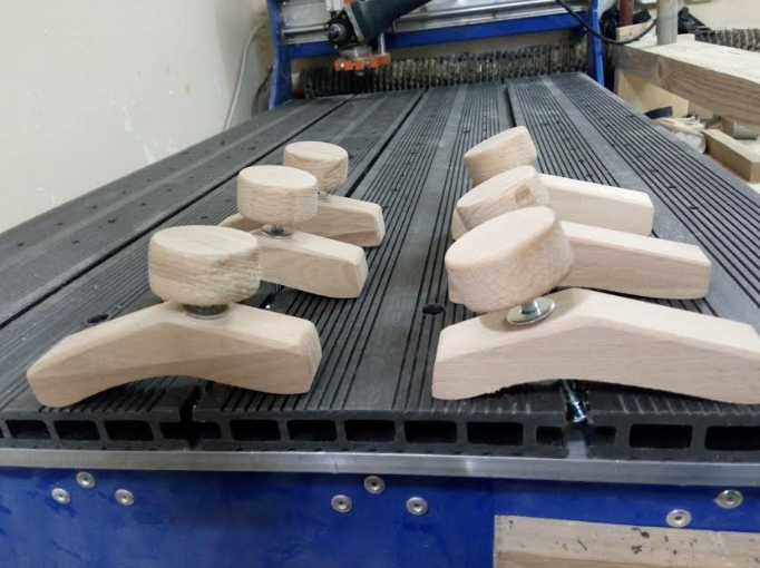
Bolted the boards directly to the aluminum home table. The bonus turned out convenient grooves for the workpiece clamps and quick installation of the filler table. All about everything took a couple of hours and ~ 1100r.
And second, finally, he wrote more or less usable software for managing non-standard CNC functions. About this will be the main story.
Formulation of the problem
G-code for operations that are described in the second part is the simplest. However, the process of setting up cannot be called quick.
How did this happen
For example, it was necessary for the additive: knowing the width of the panel, calculate how many holes there should be, calculate the exact distance between them, create a file, write g-code, load it into Mach3. All this takes, at best, 15 to 20 minutes. In this light, the advantages of a digital machine are considerably less than that of a hand-held tool, which can fill a whole bunch of holes during this time.
What I wanted to get
In the case of the same additive, I wanted to get a program where, in a very simple interface, I would enter the width and thickness of the panel and pressing the button would start the process of drilling the required number of filler holes at the same distance from each other.
Finding a solution
The first thing that came to mind was writing a standalone program that would directly interact with the parallel port. A quick googling showed that the task of writing to lpt is completely solvable, but the devil is known to hide in the details. Further study of the issue, I realized that you can get stuck here seriously and for a long time. Moreover, such a solution would not be flexible: for another machine, for example with USB, it would not work.
There was an option to deal with the SDK Mach3. In the process of collecting information about the creation of mach-plug-ins, I came across an interesting solution. It described how using OLE mechanisms you can pull Mach3 from a third-party application. I am not an expert in Microsoft technologies, but after viewing the SDK Mach3 manual diagonally, if I got the basic idea correctly, no silver bullet exists, the plugins use the same public methods of Mach3 COM objects. I did not intend to redraw the Mach3 interface, so the difference for the user between the plug-in and the standalon application was only that the plug-in was accessible from the Mach3 menu, and the application — through an icon on the XP desktop.
A separate application seemed to me preferable. In this case, theoretically, I could immediately after starting the computer start my program, which would load Mach3 with a steam locomotive (instead of loading Mach3 first and then digging into its menu to launch the plugin).
We take up the sword
Last time I had to write a native desktop application for Windows a year, in 2006, and it was in Delphi. Since then, web technologies with their Linux have completely absorbed me. Therefore, now I didn’t have special preferences in which language to sculpt a windows program. The simple example found was written in C #, and this language was chosen as a guinea pig.
I will not post here the entire code of the resulting application (if you prefer, you can find it on github via the link at the bottom of the post). I will explain the main things. I did all the experiments on a virtual machine with WinXP SP3, VS 2003 and Mach3 Version R3.043.062. For those who believe that it is better to see once the link to the video in Youtube that I understood. Below is a transcript of the highlights.
Training
- In order for Visual Studio to properly pick up the Mach3 component, it is necessary that it be correctly registered in the registry. To do this, download the file Mach3Registry.reg
- Run Mach3Registry.reg
- We launch VS, we create the project of the window application on C #
- In the Solution Explorer block, right-click on References, select Add Reference in the menu. In the opened window, click Browse and look for Mach3.exe.
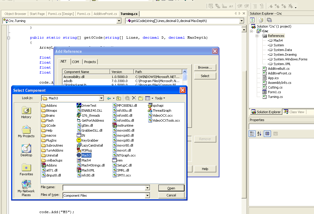
If everything is correct, a line should appear in the References list, who would have thought Mach4 ... - 5. Further we draw UI, we hang up processors, we implement algorithms ...
Interaction with Mach3
We connect the necessary libraries, we declare variables (Form1.cs)
...
using System.Runtime.InteropServices;
using Mach4; // Подключаем компонент Machnamespace Cnc
{
    publicclassForm1 : System.Windows.Forms.Form
    {
        private IMach4 _mach;
        private IMyScriptObject _mInst;
        ...
        // получение ссылки на запущенный экземпляр Mach3privatevoidGetMachInstance(){
            try
            {
                _mach = (IMach4) Marshal.GetActiveObject("Mach4.Document");
                _mInst = (IMyScriptObject) _mach.GetScriptDispatch();
            }
            catch
            {
                _mach = null;
                _mInst = null;
            }
        }
...
Using:
GetMachInstance(); // if(_mInst != null)
{
    _mInst.DoOEMButton(1003); // Нажатие на кнопку Stop в Mach3
    _mInst.Code("G00 X100"); // Выполнение G-code
    _mInst.GetOEMDRO(800); // Получить текущее значение координаты X
}
The codes of buttons and parameter values can be viewed on the wiki: OEM_DROs and OEM_Buttons (their wiki podglyuchivaet, the values of parameters in the table are not displayed, I looked at the tab “View source”).
The first version of the program worked like this: according to the set parameters, g-code was generated which was frame-by-frame (ie, line by line) executed by the _mInst.Code method . And that was my mistake. In the debugging environment on virtualke everything worked fine. In Mach3 ran the correct numbers in the coordinates. But when transferring to the machine computer, problems arose. The carriage moved correctly, but the spindle did not turn on.
It seems that the management of the router and the spindle in Mach works in different threads. It turned out that the movement commands (G ...) were executed sequentially as they entered the _mInst.Code method in one thread, and the spindle control commands (M3, M5), regardless of the first, were executed in another thread. As a result, the spindle was turned on (M3) and then turned off (M5), while the carriage movement went on as usual.
I tried different options, connected delays, tried to drive the whole manager g-code into one line and send it in one piece in _mInst.Code. As a result, I stopped at the “head on” solution: I simply pushed the generated code into a file, I open this file programmatically in Mach3, and in the same place programmatically press the “Start” button. Fragment of working code:
_mInst.LoadFile("C:\\tmp\\gcode.txt");
System.Threading.Thread.Sleep(2000);
_mInst.DoOEMButton(1000);
A pause between downloading a file and pressing a button is necessary in order for Mach to have time to open the file. Perhaps there is some more elegant way. If anyone knows, write in the comments.
An added bonus of this solution is that you can now observe the visualization of the processing process in the Mach interface.
What is the result?
Further, in a few words about the resulting application. I will separately tell about UI for each operation.
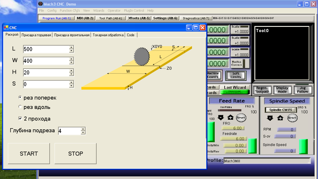
Cutting
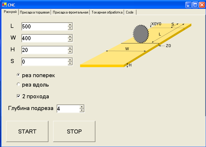
It's all quite transparent. The parameter S is needed to compensate for the size L if the workpiece is not fixed at the zero point in X (or Y in cutting along).
Additive
For additive, 2 snap configurations are possible. The first with a grinder for drilling end holes. And the second one with a conventional spindle for drilling in the plane of the shield (for some reason I called it “Frontal Additive”).
Additive face

When the end additive is important to accurately set zero in the lower right corner of the workpiece (I have there is the angle of the side fence and the table). It is not difficult to do this with a wood drill - there is a sharp tip that you need to get into this corner. Fixing the workpiece on the table, I just put it in the drill.
Without changing the equipment in the same way, I make reciprocal holes by securing the workpiece vertically:
The parameter X is needed in order to connect panels of different widths (for example, when the lower and upper panels of the cabinet are wider than the width of the side doors).
Frontal Additive
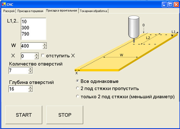
The tooling for the front is a normal spindle. This type of additive is used when you need to drill holes in a horizontal surface, not only at the edges but also somewhere in the middle. For example, if the cabinet has several compartments and there are internal besides the side walls. If the length of the panel is greater than the length of the machine, the additive can be made in 2 sets with a turn of the part by 180 degrees. In this case, the X parameter is also useful.
Turning

For me, the main difficulty in preparing the g-code with the turning path was not to overdo it with the maximum depth of the disk. The fact is that at the exit from Inkscape one line is obtained and the turning occurs in one pass. Because of this, I had to make a separate code for the cylinder billet, and only after that the main pass started creating the form. And there were some restrictions on this form. In particular, it was necessary to ensure that the trajectory did not go too deep. I tried not to go beyond 10 - 15mm from the level of the original cylinder.
All the above problems were solved in the new program. It works like this: load the “raw” g-code obtained from Inkscape, set the size of the side of the bar of the workpiece and specify the maximum depth of processing in 1 pass (the harder the wood, the less this depth). Based on the original g-code and parameters, the program will calculate the safe trajectory and send it to the CNC.
Future plans
The program has greatly simplified the routine, but it is still far from perfect. First, it will be necessary to optimize the algorithm for drilling deep holes (the drill is clogged with chips and overheats, you need to make a swing back and forth). Secondly, the idea to make a library of turning forms. Those. several typical forms (such as a cylinder, a cone, a rolling pin, etc.) with the ability to customize dimensions without the need to create trajectories in third-party programs.
Links
→ Mach3Registry.reg
→ Mach3 SDK and other programs
→ The project repository on Github (I apologize in advance to the Sharpikov for architectural jambs - this is my first C # program).