How to write in an assembler program with overlapping instructions (another bytecode obfuscation technique)
- Tutorial
We present to your attention the technique of creating assembler programs with overlapping instructions, - to protect the compiled byte-code from disassembling. This technique is able to withstand both static and dynamic bytecode analysis. The idea is to pick up such a stream of bytes, when disassembling which starting from two different offsets, two different chains of instructions were obtained, that is, two different ways of executing the program. To do this, we take multibyte assembly instructions, and hide the protected code in the variable parts of the byte code of these instructions. In order to deceive the disassembler, setting it on the wrong track (by disguising the chain of instructions), and protecting the hidden chain of instructions from its gaze.

Three necessary conditions for creating an effective "overlap"
In order to deceive the disassembler, the overlapping code must satisfy the following three conditions: 1) The instructions from the masking chain and the hidden chain must always intersect with each other, i.e. Must not be aligned relative to each other (their first and last bytes must not be the same). Otherwise, part of the hidden code will be visible in the masking chain. 2) Both chains should consist of plausible assembler instructions. Otherwise, the masking will be detected already at the stage of static analysis (having encountered an unsuitable code, the disassembler will correct the command pointer and expose the masking). 3) All instructions of both chains must be not only plausible, but also correctly executable (to avoid this, the program crashed when you try to execute them). Otherwise,
Description of the technique of "overlapping" assembly instructions
In order for the process of creating an overlapping code to be as flexible as possible, it is necessary to select only those multibyte instructions that have as many as possible bytes can take an arbitrary value. These multibyte instructions will make up a masking instruction chain.
Pursuing the goal of creating an overlapping code that will satisfy the three conditions listed above, we consider each masking instruction as a sequence of bytes of the form: XX YY ZZ.
Here XX is the instruction prefix (instruction code and other static bytes, which cannot be changed).
YY are bytes that can be changed arbitrarily (as a rule, these bytes store the immediate numeric value passed to the instruction; or the address stored in the operand's memory). YY bytes should be as large as possible - so that they contain more hidden instructions.
ZZ are also bytes that can be changed arbitrarily, with the only difference that the combination of ZZ bytes with the following bytes XX (ZZ XX) should form a valid instruction that satisfies the three conditions formulated at the beginning of the article. Ideally, ZZ should occupy only one byte, so that on YY (this is in fact the most important part - here our hidden code is located) there are as many bytes as possible. The last hidden instruction must end in ZZ, - creating a convergence point for two chains of execution.
Gluing instructions
The combination of ZZ XX - we will call the gluing instruction. The gluing instruction is necessary, firstly, for joining hidden instructions that are located in adjacent masking instructions and, secondly, to fulfill the first necessary condition, voiced at the beginning of the article: the instructions of both chains must always intersect with each other (therefore, the gluing instruction always is located at the intersection of two masking instructions).
The gluing instruction is executed in a hidden chain of commands, and therefore must be chosen in such a way as to impose as few restrictions on the hidden code. Suppose if, when it is executed, the general-purpose registers and the EFLAGS register change, then the hidden code will not be able to effectively use the corresponding registers and conditional commands (for example, if there is a comparison operator before the gluing instruction, and the gluing instruction itself changes the value of the EFLAGS register, which is after the gluing instruction - it will work incorrectly).
The above description of the overlap technique is illustrated in the following figure. If execution begins with the initial bytes (XX), then the masking chain of instructions is activated. And if from YY bytes, the hidden chain of instructions is activated.

Assembly instructions suitable for the role of "masking instructions"
The longest of the instructions, which at first glance suits us best, is the 10-byte version of MOV, where the first operand is the offset specified by the register and the 32-bit address, and the second operand is the 32-bit number. In this manual, the most bytes that can be changed arbitrarily (as many as 8 pieces).

However, although this instruction looks plausible (theoretically, it can be executed correctly), it still does not suit us, because its first operand will usually point to an unavailable address, and therefore when trying to perform such a MOV, the program will collapse. So This 10-byte MOV does not satisfy the third necessary condition: all instructions of both chains must be correctly executed.
Therefore, we will choose to play the role of masking instructions only those applicants who do not create the risk of a program crash. This condition significantly narrows the range of instructions suitable for creating an overlapping code, but there are still suitable ones. Below are four of them. Each of these four instructions has five bytes, which can be changed arbitrarily, without the risk of a program crash.
- LEA. This instruction calculates the memory address specified by the expression in the second operand, and stores the result in the first operand. Since we can refer to memory without actually accessing it (and, accordingly, without the risk of a program crashing), the last five bytes of this instruction can take arbitrary values.

- CMOVcc. This instruction performs the MOV operation if the condition "cc" is fulfilled. In order for this instruction to satisfy the third requirement, the condition must be chosen in such a way that under any circumstances it will be FALSE. Otherwise, this instruction may attempt to access an unavailable memory address, and so on. bring down the program.

- SETcc. Acts on the same principle as CMOVcc: sets a byte to one if the "cc" condition is met. This instruction has the same problem as CMOVcc: accessing an invalid address will cause the program to crash. Therefore, the choice of the condition "cc" must be approached very carefully.

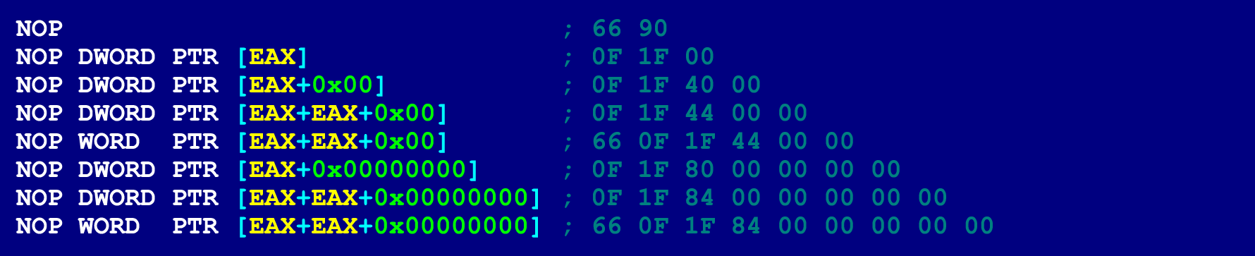
- Nop. NOPs can be of different lengths (from 2 to 15 bytes), depending on which operands are indicated in them. At the same time, there will be no risk of collapsing the program (due to accessing an invalid memory address). Because the only thing that NOPs do is increase the instruction counter, (they do not perform any operations on the operands). Therefore, the NOP bytes, in which the operands are specified, can take an arbitrary value. A 9-byte NOP is best for our purposes.

For reference, here are a few other options for NOP.
Assembly instructions suitable for the role of "gluing instructions"
The list of instructions suitable for the role of gluing instruction is unique for each specific masking instruction. Below is a list (generated by the algorithm shown in the figure below) using the example of a 9-byte NOP.

In forming this list, we took into account only those variants in which ZZ takes 1 byte (otherwise there will be little space left for the hidden code). Here is a list of suitable gluing instructions for a 9-byte NOP.

Among this list of instructions there is no one that would be free from side effects. Each of them changes either EFLAGS or general registers, or both. This list is divided into 4 categories, - according to the side effect the instruction has.
The first category includes instructions that change the EFLAGS register, but do not change the general purpose registers. Instructions from this category can be used when there are no conditional jumps in the chain of hidden instructions and any instructions that are based on the evaluation of information from the EFLAGS register. This category in this case (for 9-byte NOP'a) includes only two instructions: TEST and CMP.

Below is a simple example of hidden code that uses TEST as the gluing instruction. This example makes the exit system call, which for all Linux versions returns 1. In order to correctly form the TEST instruction for our needs, we will have to set the last byte of the first NOP, the value 0xA9. This byte, when concatenated with the first four bytes of the next NOP (66 0F 1F 84), will become a TEST EAX instruction, 0x841F0F66. The following two figures show the corresponding assembler code (for the masking chain and hidden chain). The hidden chain is activated when control is transferred to the 4th byte of the first NOP.


The second category includes instructions that change the values of general-purpose registers or available memory (stack, for example), but do not change the EFLAGS register. When executing the PUSH instruction or any variant of MOV, where the immediate operand is specified as the second operand, the EFLAGS register remains unchanged. So the gluing instructions of the second category can be placed even between the comparison instruction (TEST, for example) and the instruction evaluating the EFLAGS register. However, instructions in this category limit the use of the register, which appears in the corresponding gluing instruction. For example, if MOV EBP, 0x841F0F66 is used as a gluing instruction, then the possibilities of using the EBP register (from the rest of the hidden code) are significantly limited.
The third category includes instructions that change both the EFLAGS register and the general purpose registers (or memory). These instructions have no clear advantages compared to the instructions from the first two categories. However, they can also be used, because they do not conflict with the three conditions formulated at the beginning of the article. The fourth category includes instructions, under which there is no guarantee that the program will not collapse - there is a risk of improper access to memory. They are extremely undesirable. they do not satisfy the third condition.
Assembly instructions that can be used in a hidden chain
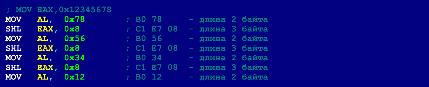
In our case (when 9-byte NOPs are used as masking instructions), the length of each instruction from the hidden chain should not exceed four bytes (this restriction does not apply to gluing instructions that take 5 bytes). However, this is not a very critical limitation, because most instructions that have a length of more than four bytes can be decomposed into several shorter instructions. Below is an example of a 5-byte MOV'a, which is too large to be placed in a hidden chain.

However, this five-byte MOV can be decomposed into three instructions, the length of which does not exceed four bytes.

Masking enhancement by scattering masking NOPs throughout the program
A large number of consecutive NOP'ov looks, from the point of view of the reverse, very suspicious. Sharpening his interest in these suspicious NOPs, an experienced reverser can get to the code hidden in them. To avoid such exposure, you can disperse masking NOPs - throughout the program.
The correct chain of execution of the hidden code in this case can be supported by two-byte unconditional branch instructions. In this case, the last two bytes of each NOP will occupy a 2-byte JMP.
Such a trick allows you to break one long sequence of NOPs into several short ones (or even use one NOP at all). In the last NOP of such a short sequence, only 3 bytes of the payload can be placed (the 4th byte will be taken by the unconditional branch instruction). So here there is an additional limit on the size of valid instructions. However, as mentioned above, long instructions can be laid out on a chain of shorter instructions. Below is an example of the same 5-byte MOV, which we have already laid out in order to meet the limit of 4 bytes. However, now we will decompose this MOV so that it is within the limit of 3 bytes.
Having laid out all the long instructions for shorter on the same principle, we can, for the purpose of greater masking, - in general only single NOPs, scattered throughout the program, to use. Double-byte JMP instructions can jump forward and back 127 bytes, which means that two consecutive NOPs (consecutive, in terms of a chain of hidden instructions) must be within 127 bytes.
Such a trick has another significant advantage (besides enhanced masking): it can be used to place hidden code in already existing NOPs of a compiled binary file (i.e., insert a payload into a binary after it is compiled). At the same time, it is not necessary that these abandoned NOPs be 9-byte. For example, if there are several single-byte NOPs in a row in a binary, they can be converted to multibyte NOPs, without affecting the functionality of the program. Below is an example of the NOP'ov technique of dispersion (this code is functionally equivalent to the example discussed just above).

Such hidden code hidden in the NOPs scattered throughout the program is much harder to detect.
An attentive reader probably noticed that the first byte of the first NOP is not claimed. However, there is nothing wrong with that. Because this unclaimed byte is preceded by an unconditional jump. So control over it will never be transferred. So everything is fine.
This is the technique for creating overlapping code. Use on health. Hide your precious code from prying eyes. But only adopt some other instruction, and not a 9-byte NOP. Because reversers will probably also read this article.