Workshop "Intel IoT". Edison - the mighty “baby”
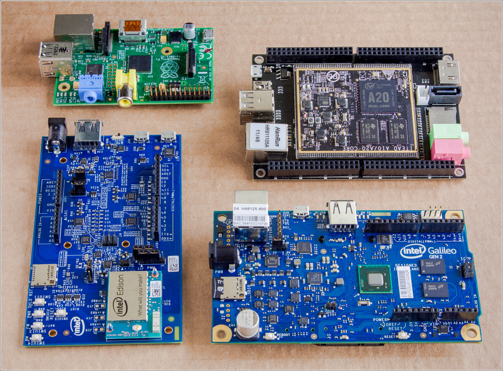
 In the previous parts of the "workshop" we considered Intel Galileo, which the manufacturer is positioning as a "for study" board. But there is also a device that can be used not only for familiarization and prototyping, but also for embedding in final products.
 It's about Intel Edison . The module is very powerful (CPU - dual-core Intel Atom 500MHz, MCU - Intel Quark 100MHz), 4GB of flash memory, 1GB of RAM, compact (a little more than an SD card), can be powered by batteries or accumulators, equipped with wireless interfaces ( Wi-Fi and Bluetooth 4.0) and much more.
But let's not get ahead of ourselves.
Unboxing and first acquaintance
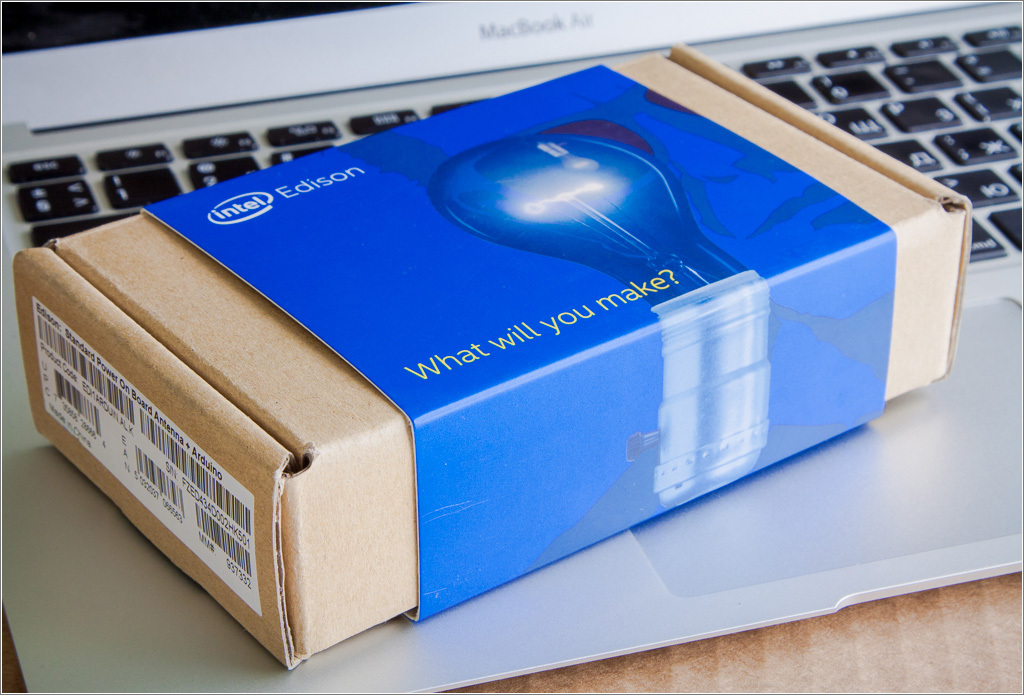
The kit I studied comes in such a nice and compact package:
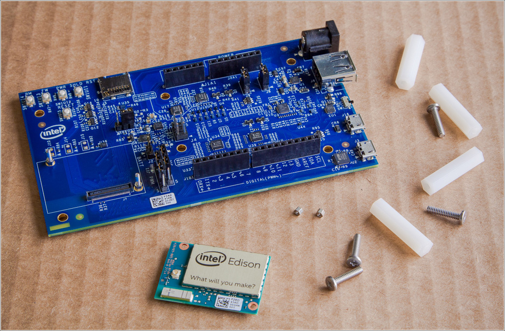
In addition to the "main module" Intel Edison, the kit includes:
- expansion board (in this set - “arduino-compatible”, there are even more compact boards for prototyping);
- four plastic racks with fixing screws;
- two nuts for mounting Intel Edison on the expansion board.
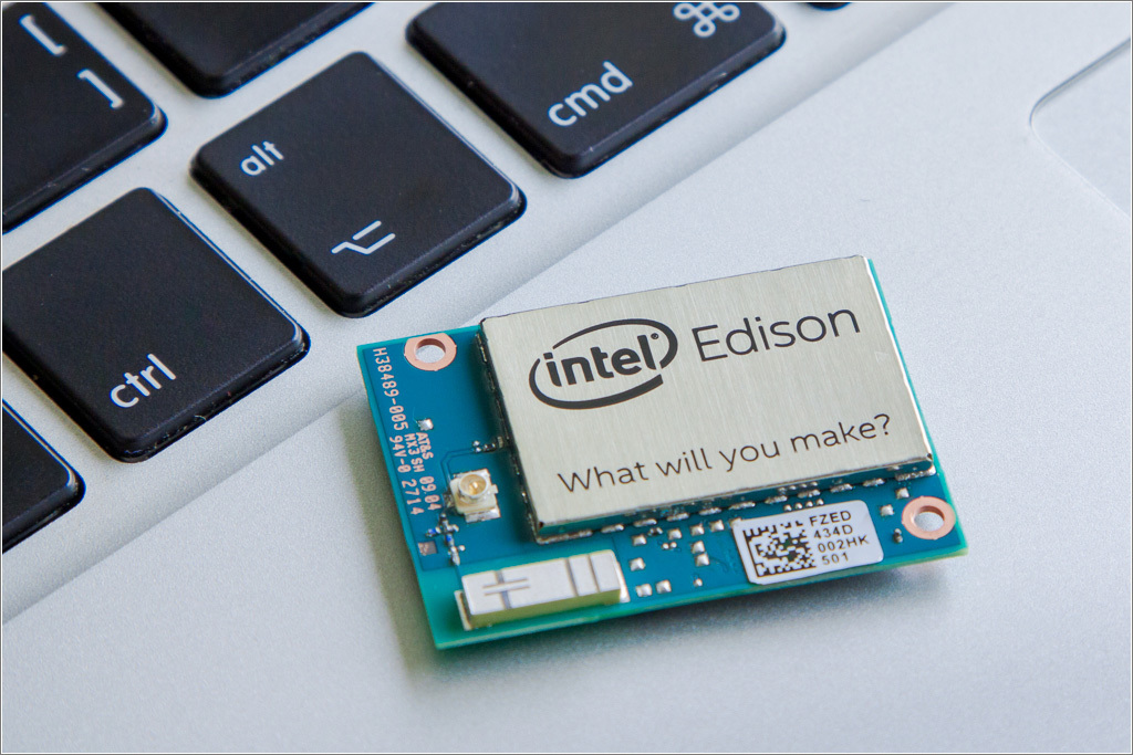
Intel Edison is immediately impressive ... for its size - after all, in this small device (size 35.4x25.0x3.9 mm), a fairly serious " filling " is enclosed :
- dual-core processor (Intel Atom, with a clock frequency of 500 MHz);
- microcontroller (Intel Quark, clock frequency - 100MHz);
- RAM - 1GB LPDDR3;
- flash - 4GB (eMMC);
- Wi-Fi module - Broadcom 43340 802.11 a / b / g / n (dual-band - 2.4 and 5 GHz), built-in antenna (in my case, there is an option with an external antenna),
- bluetooth 4.0 module
Almost all components are hidden under a metal screen. A ceramic antenna for wireless modules (bottom left) and a connector (u.FL) for connecting an external antenna (slightly higher) are visible on the “front” side of the board.
You must admit that few systems can boast of such a “set”. And all this in a tiny performance.
On the underside of the board is another “shielded box” with components and a connector through which Edison communicates with the “outside world”:
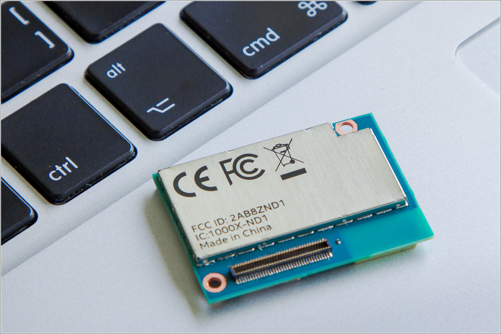
The following interfaces are displayed through this connector:
- SD card - 1 piece
- UART - 2 ports
- I2C - 2 tires
- SPI - 1 bus with a choice of 2 chips (2 CS)
- I2S - 1 bus
- I / O ports (GPIO) - 12 pieces (4 of them are with PWM capability)
- USB 2.0 - 1 port (OTG)
- Clock output - 32kHz and 19.2MHz
And this connector is also impressive for its size - 70 contacts on such a small area.
The use of just such a connector, apparently, is a compromise between the desire to display as many interfaces as possible and the desire to do this as compactly as possible.
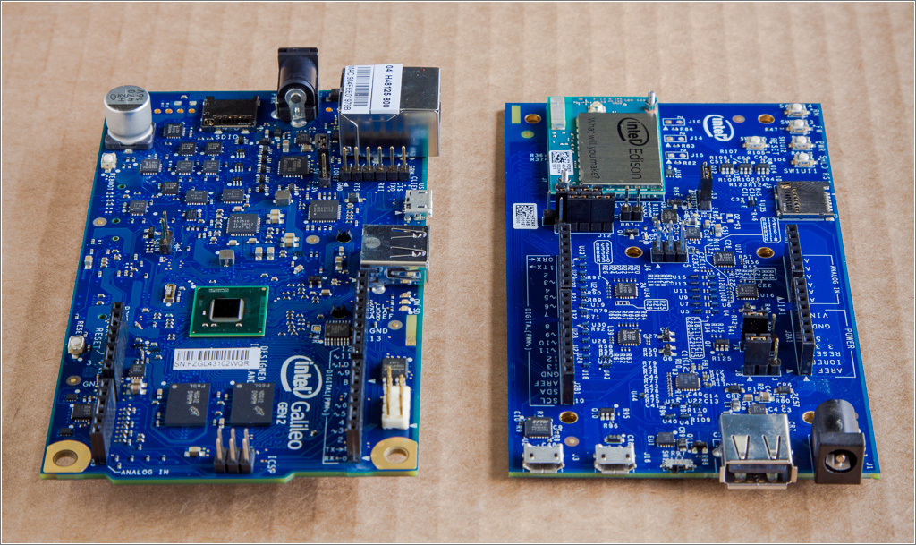
The board that went into production doesn't look as impressive as Intel Edison originally presented: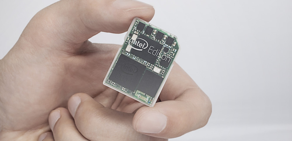
But still, Edison is a very outstanding product.
But still, Edison is a very outstanding product.
At home, I'm afraid it will be very difficult to make a prototype of my device based on Intel Edison. But for prototyping, the board from the delivery kit is perfect:
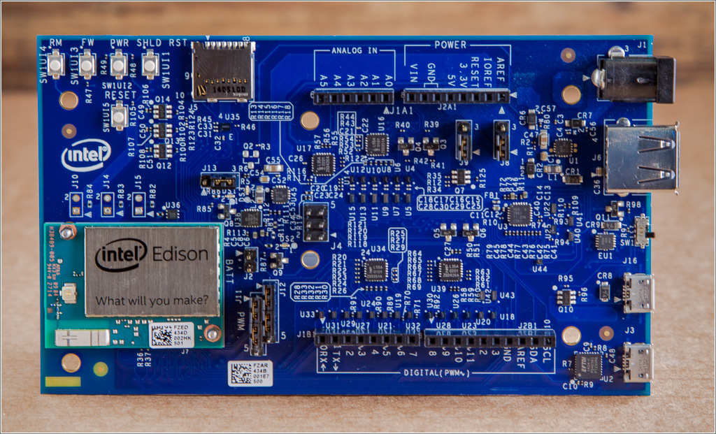
In addition to Edison, “pins” for connecting arduino-compatible shields (marked as “ANALOG IN”, “DIGITAL”, “POWER”), a microSD card slot, a power supply connector and three USB connectors ( one is type A and two are microUSB).
I’ll tell you right away why there are so many usb connectors, because Intel Edison itself has only one OTG port. It's all about
There are also 5 buttons on the board:
- FW and RM - to restore performance in case of damage to the "image"
- PWR - power management
- SHLD RST - reload arduino sketch working in Intel Edison (does not affect the state of Edison itself)
- RESET - reset.
This document describes the functions and possibilities of using buttons in more detail .
To control the various operating modes of Intel Edison and connect additional modules, the following pins, connectors and jumpers are also located on the board:
- IOREF - to select the voltage level with which the board will work: 5V or 3.3V;
- AREF - selection of the reference voltage for the operation of the ADC (also depends on the position of the IOREF jumper);
- NTC - pins for connecting a thermistor (at 10 kOhm) to control the temperature of the battery when charging. When these pins are closed - the temperature control function is blocked;
- ICSP - performs the same functions as the connector of the same name on the Arduino UNO board;
- BATT - pins for connecting a Li-Ion or Li-Po battery for the development of "wearable" electronics (do not reverse the polarity!);
- PWM - jumpers for configuring the operation of PWM outputs.
Read more here .
I found a 3.7V 1000mAh Li-Po battery in my household
And I, of course, connected it to the corresponding connector - the board immediately “wound up”. There is a “charger” for such batteries on the board. Accordingly, you can use such batteries, for example, as a backup power source.
For more information on the features of using batteries, see this document .
For more information on the features of using batteries, see this document .
By the way, Intel Edison was designed including for use in "wearable" electronics, so with consumption here everything is already very good. In the specification, these characteristics are indicated (in standby mode):
- all radio modules are off - 13mW;
- included Bluetooth 4.0 - 21.5mW;
- Wi-Fi enabled - 35mW;
Naturally, in the active mode, not everything will be so good, but it already depends on what you will implement and how to optimize the consumption of the system.
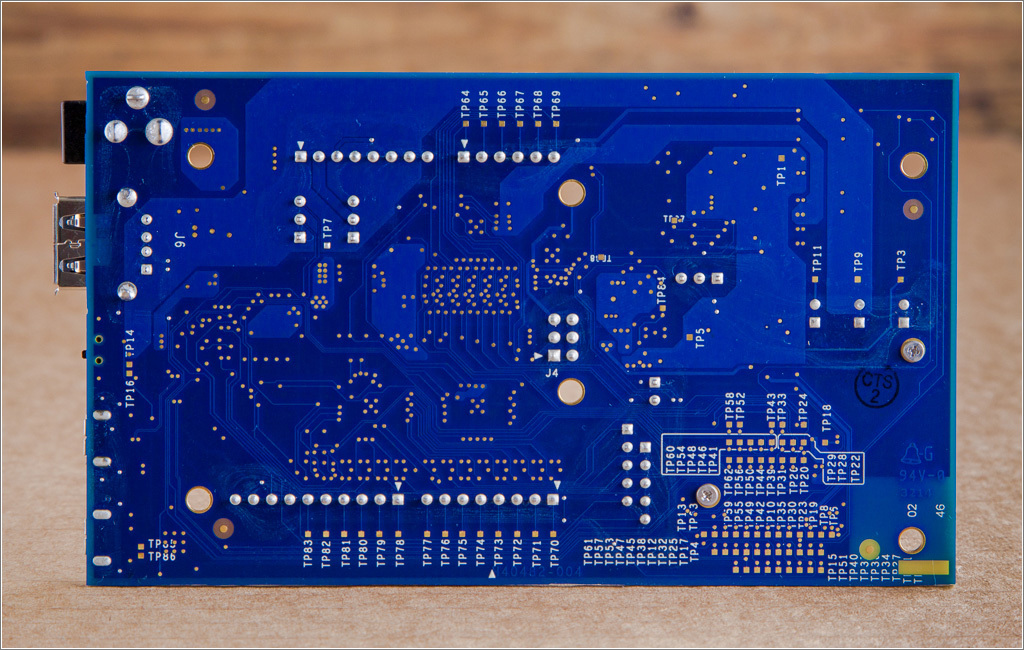
On the bottom side of the board there is nothing interesting, except for a large number of contact pads (apparently, in order to be able to connect “directly” to Edison ports):
To prototype more compact devices it is better to use just such a board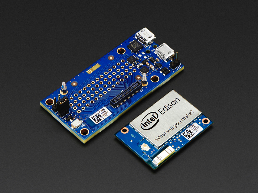
After we have thoroughly reviewed Edison and the expansion board, let's get started with the setup.
Intel Edison Firmware
Let's prepare our “device”. To do this, you need to carefully place Intel Edison on the expansion board (convenient guides practically do not give a chance for an error), so that the connector is connected - you need to lightly click on Edison until it clicks (you need to press gently in the connector area and without unnecessary efforts). Now you can fix the boards between each other with the small nuts from the delivery.

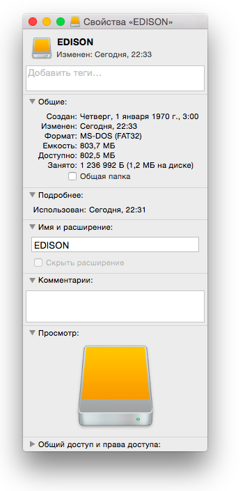
For initial setup, you need to connect 2 USB-cables (in microUSB-connectors), switch SW1 should be in position to microUSB. We connect both cables to the computer (I use mac again). If everything is done correctly, an EDISON disk will appear in the system.
First, it is recommended to delete the existing image, for which we simply delete everything from the appeared disk, including hidden folders, using any available tool (I used the terminal).
We look at the properties of the EDISON drive. If there is anything other than FAT16 - everything is in order, if FAT16 - we treat like that .
Running a little ahead
After the firmware will be approximately the following picture:
root@edison:~# df -h
Filesystem                Size      Used Available Use% Mounted on
/dev/root               463.9M    365.9M     62.2M  85% /
devtmpfs                479.9M         0    479.9M   0% /dev
tmpfs                   480.2M         0    480.2M   0% /dev/shm
tmpfs                   480.2M    508.0K    479.7M   0% /run
tmpfs                   480.2M         0    480.2M   0% /sys/fs/cgroup
systemd-1                 5.7M      5.3M    462.0K  92% /boot
tmpfs                   480.2M      4.0K    480.2M   0% /tmp
tmpfs                   480.2M         0    480.2M   0% /var/volatile
/dev/mmcblk0p5         1003.0K     21.0K    911.0K   2% /factory
/dev/mmcblk0p7            5.7M      5.3M    462.0K  92% /boot
systemd-1                 2.2G      5.3M      2.2G   0% /home
/dev/mmcblk0p10           2.2G      5.3M      2.2G   0% /home
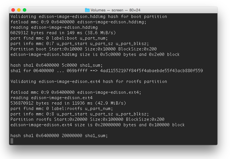
Download the latest version of Yocto . We unpack the archive and copy all the resulting files and folders to the EDISON drive. After the files are overwritten, you need to flash Edison. To do this, open a new terminal window (or use what was in the previous steps).
Enter the command:
screen /dev/cu.usbserial
And press the Tab key (for autocomplete), then add “115200 -L”, I got this:
screen /dev/cu.usbserial-AJ035QHB 115200 -L
Confirm the input (Enter) - we see a "blank screen", Enter again and we get a welcome window:
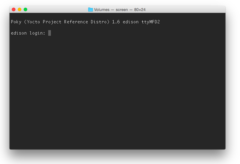
Enter the root login. Enter the password (if your system has already been configured earlier and this is an “update”). After that, the easiest way is to start the firmware using the command:
reboot ota
Attention, this will delete all the settings that were made earlier (for example, Wi-Fi, etc.). If this is done for the first time, you will not lose anything. The update process looks something like this:
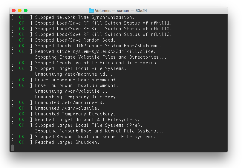
If all is well, the process will end with an invitation to login:
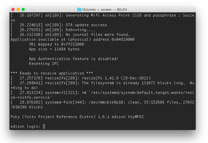
All settings are reset - root login (no password).
Linux version
root@edison:~# cat /proc/version
Linux version 3.10.17-poky-edison+ (sys_dswci@tlsndgbuild004) (gcc version 4.8.2 (GCC) ) #1 SMP PREEMPT Fri Jan 30 14:16:35 CET 2015
Initial setup
To configure Intel Edison, run the following command:
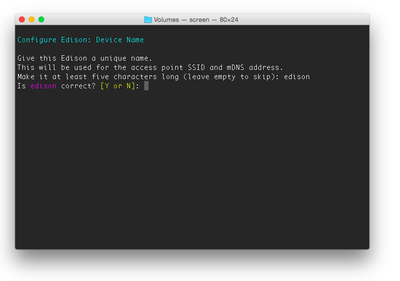
configure_edison --setup
This command launches the installation "wizard", during which it is proposed to set sequentially:
- Administrative Entry Password
- Device name
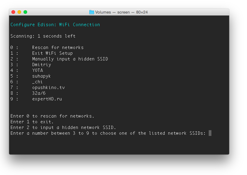
Done. Now you can safely disconnect Edison from the computer and connect it with a power supply (7-15V). The device starts automatically and connects to the selected wireless network.
Now Intel Edison can be controlled via SSH (IP address, login / password - everything is already defined in the previous steps).
You can repeat the settings that we have already made in one of the previous parts of the Workshop .
In addition, you can connect a memory card (microSD) and use it at your discretion.
Blink LED with Arduino IDE
From the moment of writing the previous parts of the "workshop", the version of the Arduino IDE has grown a bit to 1.6.0 . In general, there is nothing fundamentally different from what was in the example with Intel Galileo Gen2 - you only need to select the correct board (Edison) and port (for Mac it is a port with the name of the form /dev/cu.usbmodemxxxx).
If everything is done correctly, then on the board (after loading the Blink example), the DS2 LED will blink. Now you can learn other features of Intel Edison. In order to make this quick and easy, you can purchase the Grove Starter Kit Plus Intel IoT Edition , which contains the most popular elements: various sensors, a display, etc.
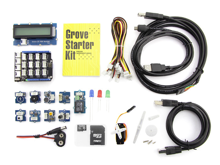
I already used a similar set earlier
To create a weather station . It is possible that you already have such a “whale” (or a similar one in meaning) is already available (the probability of this is very high if you have already started / mastering the Arduino). Anyway, all those “shields” that are used with the Arduino (with some reservations) can be used with Intel Edison and the “big” board.
And further facilitates the process of studying the presence of all the necessary examples .
Actually, as declared - the transition from Intel Galileo to Intel Edison is very simple: everything that was done for Galileo is simply transferred to the "older" device.
What's next?
You can choose any development method that you like. The choice is offered:
By the way, since the publication of the previous parts of the "workshop", the Intel IoT Developer Kit has also been updated (the current version is v1.0). During its development, numerous comments and suggestions were taken into account (including those that were touched upon in our "workshop") - it became easier to create projects in Eclipse, even more examples, more documentation (moreover, some are already in Russian) .
conclusions
Intel Galileo and Intel Edison are promising devices that allow not only to plunge into the world of developing devices on microcontrollers, but also use the serious capabilities of Linux computers (and, in the case of Edison, also quite powerful SoC equipment).
The interaction of these rich (by themselves) components significantly expand the possibilities of use: for example, on the linux component, you can raise a web server with a database to organize a convenient web interface for controlling any devices, and the “iron” (arduino) component - implements this management.
More devices are good and different.
" The first part of the" workshop ": Galileo Gen2 - The first acquaintance
" The second part of the "workshop": Galileo Gen2 - Linux & Arduino
" The third part of the" workshop ": The workshop " Intel IoT ". Galileo Gen2 - Eclipse & libmraa + UPM
Well, the latest news:
» Intel Edison officially in Russia: pre-order and competition of projects
Thank you for your attention!