GPU Particles using Compute and Geometry Shaders
- Tutorial
Hello dear reader!
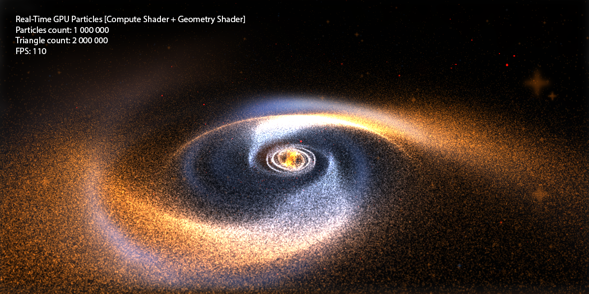
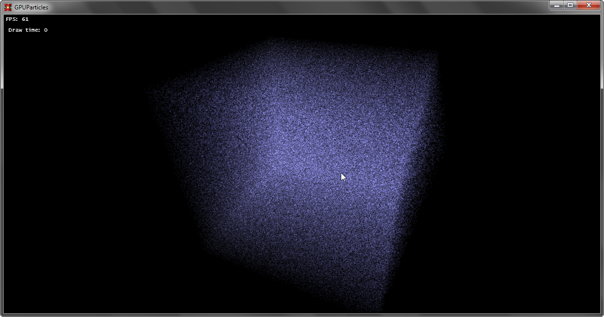
Today we will continue to study the graphics pipeline, and I will talk about such wonderful things as Compute Shader and Geometry Shader on the example of creating a system for 1,000,000+ particles, which in turn are not points, but squares ( billboard quads ) and have their own texture. In other words, we will derive 2,000,000+ textured triangles with FPS> 100 (on the budget graphics card GeForce 550 Ti ).
I wrote a lot about shaders among my articles, but we always only operated on two types: Vertex Shader , Pixel Shader . However, with the advent of DX10 + , new types of shaders appeared: Geometry Shader, Domain Shader, Hull Shader, Compute Shader . Just in case, I’ll remind you what the graphics pipeline looks like now: I’ll
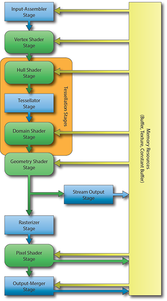
make a reservation that in this article we will not touch on Domain Shader and Hull Shader , I will write about tessellation in the following articles.
Only Geometry Shader remains unexplored . What is a Geometry Shader ?
Vertex Shader handles vertex processing, Pixel Shader handles pixel processing, and as you might guess, Geometry Shader handles primitive processing.
This shader is an optional part of the pipeline, i.e. it may not exist at all: vertexes directly enter the Primitive Assembly Stage and then the primitive is rasterized.
The Geometry Shader is between the Primitive Assembly Stage and the Rasterizer Stage .
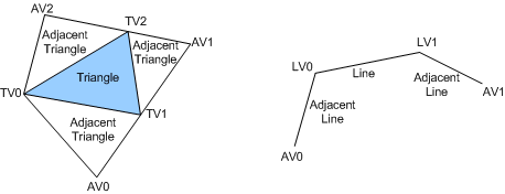
At the input, he can get information about both the assembled primitive and the neighboring primitives:
At the output, we have a stream of primitives, where we in turn add a primitive. Moreover, the type of the returned primitive may differ from the input one. For example - get Point , return Line . An example of a simple geometric shader that does nothing and simply connects an input to an output:
In DirectX10 + appeared such as the type of buffer Structured Buffer , a buffer may be described by the programmer as he pleases, i.e. in the classical sense, it is a homogeneous array of structures of a certain type, which is stored in the memory of the GPU .
Let's try to create a similar buffer for our particle system. Let us describe what properties a particle has ( on the C # side ):
And create the buffer itself ( using the SharpDX.Toolkit helper ):
Where initialParticles is an array of GPUParticleData with the size of the desired number of particles.
It is worth noting that the flags when creating the buffer are set as follows:
BufferFlags.ShaderResource - to be able to access the buffer from the shader
BufferFlags.StructuredBuffer - indicates the buffer belongs to
BufferFlags.UnorderedAccess - to change the buffer from the shader
Create a buffer of 1,000,000 elements and fill its random elements:
After that, a buffer of 1,000,000 elements with random values will be stored in our GPU memory .
Now you need to figure out how do we draw this buffer? After all, we don’t even have vertices! Vertexes we will generate on the go, based on the values of our structural buffer.
Create two shaders - Vertex Shader and Pixel Shader .
To begin with, we describe the input data for the shaders:
Well, let's take a closer look at the shaders, for starters, vertex:
In this country of magic - we just read a specific particle from the particle buffer according to the current VertexID (and it lies in the range from 0 to 999999) and using the particle position - we project into the screen space.
Well, with the Pixel Shader, it's as easy as shelling pears :
Set the color of the particle as float4 (0.1, 0.1, 0.1, 1) . Why 0.1 ? Because we have a million particles, and we will use Additive Blending .
Define the buffers and draw the geometry:
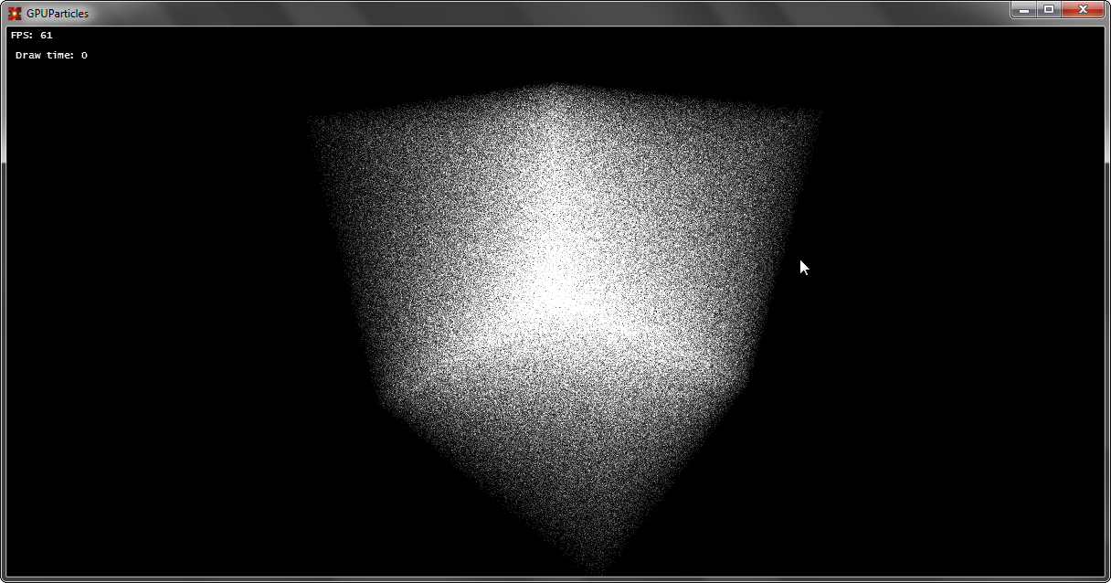
Well, let's enjoy the first victory:
If you have not forgotten the first chapter, then you can safely turn our set of points into full-fledged Billboards consisting of two triangles.
I’ll tell you a little about what QuadBillboard is : it is a square made of two triangles and this square is always turned towards the camera.
How to create this square? We need to come up with an algorithm for quickly generating such squares. Let's take a look at something in Vertex Shader . There we have three spaces when constructing SV_Position :
View Space is just what we need, because these coordinates are just relative to the camera and the plane (-1 + px, -1 + py, pz) -> (1 + px, 1 + py, pz) created in this space will always have a normal that is aimed at the camera.
Therefore, we’ll change something in the shader:
The output of SV_Position will not be transferred to ProjectionSpace-position , but to ViewSpace-position , in order to create new primitives in the Geometry Shader in ViewSpace .
Add a new stage:
Well, as we now have UV - we can read the texture in the pixel shader:
Additionally, set the sampler and particle texture for rendering:
We check, test:
Now, everything is ready, we have a special buffer in the GPU memory and there is a particle renderer built using the Geometry Shader , but a similar system is static. You can, of course, change the position on the CPU , just read the buffer data from the GPU every time , change it, and then load it back, but what kind of GPU Power can it be? Such a system will not withstand 100,000 particles.
And to work on the GPU with such buffers, you can use a special shader - Compute Shader . It is outside the traditional render-pipeline and can be used separately.
What is a Compute Shader ?
In your own words, a computational shader (Compute Shader ) is a special stage of the pipeline that replaces all the traditional ones (however, it can still be used with it), allows you to execute arbitrary code using the GPU , and read / write data to buffers (including texture buffers). Moreover, the execution of this code occurs as parallel as the developer sets up.
Let's look at the execution of the simplest code:
At the very beginning of the code there is a numthreads field that indicates the number of threads in the group. Until we use group streams and make one stream per group.
uint3 DTiD.xyz points to the current stream.
The next stage is the launch of such a shader, it is performed as follows:
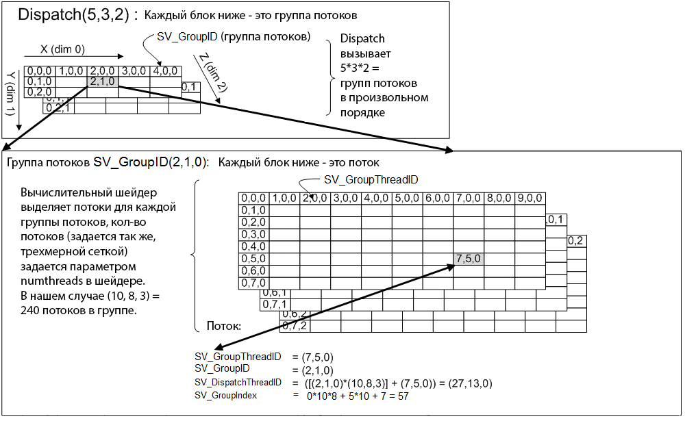
In the Dispatch method, we indicate how many stream groups we should have, and the maximum number of each dimension is limited to 65536 . And if we execute such code, then the shader code on the GPU will be executed once, because we have 1 group of threads, each group has 1 thread. If you put, for example, Dispatch (5, 1, 1) - the shader code on the GPU will be executed five times, 5 groups of threads, each group has 1 thread. If you also change numthreads -> (5, 1, 1) , then the code will execute 25 times, and in 5 groups of threads, in each group of 5 threads. In more detail you can consider if you look at the picture:
Now, back to the particle system, what do we have? We have a one-dimensional array of 1,000,000 elements and the task is to process the particle positions. Because particles move independently of each other, then this problem can be very well parallelized.
In DX10 (this is the version of CS we use to support DX10 cards) the maximum number of streams per group of streams is 768 , and in all three dimensions. I create 32 * 24 * 1 = 768 threads in total for each thread group, i.e. our one group is able to process 768 particles (1 stream - 1 particle). Next, it is necessary to calculate how many groups of flows are needed (taking into account the fact that one group will process 768 particles) in order to processNth particle count.
This can be calculated by the formula:
After that - we can call Dispatch (_groupSizeX, _groupSizeY, 1) , and the shader will be able to process the Nth number of elements in parallel.
To access a specific element, use the formula:
The following is the updated shader code:
Another magic happens here, we use our particle buffer as a special resource: RWStructuredBuffer , which means that we can read and write to this buffer.
(!) Prerequisite for writing - this buffer must be marked with the UnorderedAccess flag when creating .
Well, the final stage, we set the resource for the shader as UnorderedAccessView our buffer and call Dispatch :
After completion of the code execution, it is necessary to remove the UnorderedAccessView from the shader, otherwise we will not be able to use it!
Let's do something with particles, write a simple solver:
We set the Attractor in the constant buffer.
Compile, run and enjoy:
Speaking of particles, nothing prevents creating a complete and powerful system of particles: the points are easy enough to sort (to ensure transparency), apply the soft particles technique when drawing, and also take into account the lighting of "non-luminous" particles. Computing shaders are mainly used to create the Bokeh Blur effect (here you need more geometric ones), to create a Tiled Deferred Renderer , etc. Geometric shaders, for example, can be used when you need to generate a lot of geometry. The most striking example is grass and particles. By the way, the use of GS and CS are unlimited and limited only by the imagination of the developer.
Traditionally, I attach the full source code and demo to the post .
PS to run the demo - you need a video card with support for DX10 and Compute Shader.
I am very pleased when people show interest in what I write. And for me, the reaction to the article is very important, be it in the form of a plus or minus with a constructive comment. So I can determine which topics are more interesting to the habrasociety and which are not.
Today we will continue to study the graphics pipeline, and I will talk about such wonderful things as Compute Shader and Geometry Shader on the example of creating a system for 1,000,000+ particles, which in turn are not points, but squares ( billboard quads ) and have their own texture. In other words, we will derive 2,000,000+ textured triangles with FPS> 100 (on the budget graphics card GeForce 550 Ti ).
Introduction
I wrote a lot about shaders among my articles, but we always only operated on two types: Vertex Shader , Pixel Shader . However, with the advent of DX10 + , new types of shaders appeared: Geometry Shader, Domain Shader, Hull Shader, Compute Shader . Just in case, I’ll remind you what the graphics pipeline looks like now: I’ll
make a reservation that in this article we will not touch on Domain Shader and Hull Shader , I will write about tessellation in the following articles.
Only Geometry Shader remains unexplored . What is a Geometry Shader ?
Chapter 1: Geometry Shader
Vertex Shader handles vertex processing, Pixel Shader handles pixel processing, and as you might guess, Geometry Shader handles primitive processing.
This shader is an optional part of the pipeline, i.e. it may not exist at all: vertexes directly enter the Primitive Assembly Stage and then the primitive is rasterized.
The Geometry Shader is between the Primitive Assembly Stage and the Rasterizer Stage .
At the input, he can get information about both the assembled primitive and the neighboring primitives:
At the output, we have a stream of primitives, where we in turn add a primitive. Moreover, the type of the returned primitive may differ from the input one. For example - get Point , return Line . An example of a simple geometric shader that does nothing and simply connects an input to an output:
struct PixelInput
{
	float4 Position : SV_POSITION; // стандартный System-Value для вертекса
};
[maxvertexcount(1)] // максимальное кол-во вертексов, которое мы можем добавить
void SimpleGS( point PixelInput input[1], inout PointStream stream )
{
	PixelInput pointOut = input[0]; // получение вертекса
	stream.Append(pointOut); // добавление вертекса
	stream.RestartStrip(); // создаем примитив (для Point – требуется один вертекс)
}
Chapter 2: StructuredBuffer
In DirectX10 + appeared such as the type of buffer Structured Buffer , a buffer may be described by the programmer as he pleases, i.e. in the classical sense, it is a homogeneous array of structures of a certain type, which is stored in the memory of the GPU .
Let's try to create a similar buffer for our particle system. Let us describe what properties a particle has ( on the C # side ):
public struct GPUParticleData
{
     public Vector3 Position;
     public Vector3 Velocity;
};
And create the buffer itself ( using the SharpDX.Toolkit helper ):
_particlesBuffer = Buffer.Structured.New(graphics, initialParticles, true); Where initialParticles is an array of GPUParticleData with the size of the desired number of particles.
It is worth noting that the flags when creating the buffer are set as follows:
BufferFlags.ShaderResource - to be able to access the buffer from the shader
BufferFlags.StructuredBuffer - indicates the buffer belongs to
BufferFlags.UnorderedAccess - to change the buffer from the shader
Create a buffer of 1,000,000 elements and fill its random elements:
GPUParticleData[] initialParticles = new GPUParticleData[PARTICLES_COUNT];
for (int i = 0; i < PARTICLES_COUNT; i++)
{
	initialParticles[i].Position = random.NextVector3(new Vector3(-30f, -30f, -30f), new Vector3(30f, 30f, 30f));
}
After that, a buffer of 1,000,000 elements with random values will be stored in our GPU memory .
Chapter 3. Rendering Point-Particles
Now you need to figure out how do we draw this buffer? After all, we don’t even have vertices! Vertexes we will generate on the go, based on the values of our structural buffer.
Create two shaders - Vertex Shader and Pixel Shader .
To begin with, we describe the input data for the shaders:
struct Particle // описание структуры на GPU
{
    float3 Position;
    float3 Velocity;
};
StructuredBuffer Particles : register(t0); // буфер частиц
cbuffer Params : register(b0) // матрицы вида и проекции
{
	float4x4 View;
	float4x4 Projection;
};
// т.к. вертексов у нас нет, мы можем получить текущий ID вертекса при рисовании без использования Vertex Buffer
struct VertexInput
{
 	uint VertexID : SV_VertexID;
};
struct PixelInput // описывает вертекс на выходе из Vertex Shader
{
	float4 Position : SV_POSITION;
};
struct PixelOutput // цвет результирующего пикселя
{
    float4 Color : SV_TARGET0;
};
Well, let's take a closer look at the shaders, for starters, vertex:
PixelInput DefaultVS(VertexInput input)
{
	PixelInput output = (PixelInput)0;
	Particle particle = Particles[input.VertexID];
	float4 worldPosition = float4(particle.Position, 1);
	float4 viewPosition = mul(worldPosition, View);
	output.Position = mul(viewPosition, Projection);
	return output;
}
In this country of magic - we just read a specific particle from the particle buffer according to the current VertexID (and it lies in the range from 0 to 999999) and using the particle position - we project into the screen space.
Well, with the Pixel Shader, it's as easy as shelling pears :
PixelOutput DefaultPS(PixelInput input)
{
	PixelOutput output = (PixelOutput)0;
	output.Color = float4((float3)0.1, 1);
	return output;
}
Set the color of the particle as float4 (0.1, 0.1, 0.1, 1) . Why 0.1 ? Because we have a million particles, and we will use Additive Blending .
Define the buffers and draw the geometry:
graphics.ResetVertexBuffers(); // на всякий случай сбросим буферы
graphics.SetBlendState(_additiveBlendState); // включим Additive Blend State
// и установим наш буфер частиц как SRV (только чтение).
_particlesRender.Parameters["Particles"].SetResource(0, _particlesBuffer);
// матрицы
_particlesRender.Parameters["View"].SetValue(camera.View);
_particlesRender.Parameters["Projection"].SetValue(camera.Projection);
// установим шейдер
_particlesRender.CurrentTechnique.Passes[0].Apply();
// выполним отрисвоку 1000000 частиц в виде точек
graphics.Draw(PrimitiveType.PointList, PARTICLES_COUNT);
Well, let's enjoy the first victory:
Chapter 4: Rendering QuadBillboard Particles
If you have not forgotten the first chapter, then you can safely turn our set of points into full-fledged Billboards consisting of two triangles.
I’ll tell you a little about what QuadBillboard is : it is a square made of two triangles and this square is always turned towards the camera.
How to create this square? We need to come up with an algorithm for quickly generating such squares. Let's take a look at something in Vertex Shader . There we have three spaces when constructing SV_Position :
- World Space - vertex position in world coordinates
- View Space - vertex position in view coordinates
- Projection Space - vertex position in screen coordinates
View Space is just what we need, because these coordinates are just relative to the camera and the plane (-1 + px, -1 + py, pz) -> (1 + px, 1 + py, pz) created in this space will always have a normal that is aimed at the camera.
Therefore, we’ll change something in the shader:
PixelInput TriangleVS(VertexInput input)
{
	PixelInput output = (PixelInput)0;
	Particle particle = Particles[input.VertexID];
	float4 worldPosition = float4(particle.Position, 1);
	float4 viewPosition = mul(worldPosition, View);
	output.Position = viewPosition;
	output.UV = 0;
	return output;
}
The output of SV_Position will not be transferred to ProjectionSpace-position , but to ViewSpace-position , in order to create new primitives in the Geometry Shader in ViewSpace .
Add a new stage:
// функция изменения вертекса и последующая проекция его в Projection Space
PixelInput _offsetNprojected(PixelInput data, float2 offset, float2 uv)
{
	data.Position.xy += offset;
	data.Position = mul(data.Position, Projection);
	data.UV = uv;
	return data;
}
[maxvertexcount(4)] // результат работы GS – 4 вертекса, которые образуют TriangleStrip
void TriangleGS( point PixelInput input[1], inout TriangleStream stream )
{
	PixelInput pointOut = input[0];
	const float size = 0.1f; // размер конченого квадрата
	// описание квадрата
	stream.Append( _offsetNprojected(pointOut, float2(-1,-1) * size, float2(0, 0)) );
	stream.Append( _offsetNprojected(pointOut, float2(-1, 1) * size, float2(0, 1)) );
	stream.Append( _offsetNprojected(pointOut, float2( 1,-1) * size, float2(1, 0)) );
	stream.Append( _offsetNprojected(pointOut, float2( 1, 1) * size, float2(1, 1)) );
	// создать TriangleStrip
	stream.RestartStrip();
}
Well, as we now have UV - we can read the texture in the pixel shader:
PixelOutput TrianglePS(PixelInput input)
{
	PixelOutput output = (PixelOutput)0;
	float particle = ParticleTexture.Sample(ParticleSampler, input.UV).x * 0.3;
        output.Color = float4((float3)particle, 1);
	return output;
}
Additionally, set the sampler and particle texture for rendering:
_particlesRender.Parameters["ParticleSampler"].SetResource(_particleSampler);
_particlesRender.Parameters["ParticleTexture"].SetResource(_particleTexture);
We check, test:
Chapter 5: Particle Motion
Now, everything is ready, we have a special buffer in the GPU memory and there is a particle renderer built using the Geometry Shader , but a similar system is static. You can, of course, change the position on the CPU , just read the buffer data from the GPU every time , change it, and then load it back, but what kind of GPU Power can it be? Such a system will not withstand 100,000 particles.
And to work on the GPU with such buffers, you can use a special shader - Compute Shader . It is outside the traditional render-pipeline and can be used separately.
What is a Compute Shader ?
In your own words, a computational shader (Compute Shader ) is a special stage of the pipeline that replaces all the traditional ones (however, it can still be used with it), allows you to execute arbitrary code using the GPU , and read / write data to buffers (including texture buffers). Moreover, the execution of this code occurs as parallel as the developer sets up.
Let's look at the execution of the simplest code:
[numthreads(1, 1, 1)]
void DefaultCS( uint3 DTiD: SV_DispatchThreadID )
{
	// DTiD.xyz - текущий поток
	// ... произвольный код
}
technique ComputeShader
{
	pass DefaultPass
	{
		Profile = 10.0;
		ComputeShader = DefaultCS;
	}
}
At the very beginning of the code there is a numthreads field that indicates the number of threads in the group. Until we use group streams and make one stream per group.
uint3 DTiD.xyz points to the current stream.
The next stage is the launch of such a shader, it is performed as follows:
_effect.CurrentTechnique.Passes[0].Apply();
graphics.Dispatch(1, 1, 1);
In the Dispatch method, we indicate how many stream groups we should have, and the maximum number of each dimension is limited to 65536 . And if we execute such code, then the shader code on the GPU will be executed once, because we have 1 group of threads, each group has 1 thread. If you put, for example, Dispatch (5, 1, 1) - the shader code on the GPU will be executed five times, 5 groups of threads, each group has 1 thread. If you also change numthreads -> (5, 1, 1) , then the code will execute 25 times, and in 5 groups of threads, in each group of 5 threads. In more detail you can consider if you look at the picture:
Now, back to the particle system, what do we have? We have a one-dimensional array of 1,000,000 elements and the task is to process the particle positions. Because particles move independently of each other, then this problem can be very well parallelized.
In DX10 (this is the version of CS we use to support DX10 cards) the maximum number of streams per group of streams is 768 , and in all three dimensions. I create 32 * 24 * 1 = 768 threads in total for each thread group, i.e. our one group is able to process 768 particles (1 stream - 1 particle). Next, it is necessary to calculate how many groups of flows are needed (taking into account the fact that one group will process 768 particles) in order to processNth particle count.
This can be calculated by the formula:
int numGroups = (PARTICLES_COUNT % 768 != 0) ? ((PARTICLES_COUNT / 768) + 1) : (PARTICLES_COUNT / 768);
double secondRoot= System.Math.Pow((double)numGroups, (double)(1.0 / 2.0));
secondRoot= System.Math.Ceiling(secondRoot);
_groupSizeX = _groupSizeY = (int)secondRoot;
After that - we can call Dispatch (_groupSizeX, _groupSizeY, 1) , and the shader will be able to process the Nth number of elements in parallel.
To access a specific element, use the formula:
uint index = groupID.x * THREAD_IN_GROUP_TOTAL + groupID.y * GROUP_COUNT_Y * THREAD_IN_GROUP_TOTAL + groupIndex; The following is the updated shader code:
struct Particle
{
    float3 Position;
    float3 Velocity;
};
cbuffer Handler : register(c0)
{
	int GroupDim;
	uint MaxParticles;
	float DeltaTime;
};
RWStructuredBuffer Particles : register(u0);
#define THREAD_GROUP_X 32
#define THREAD_GROUP_Y 24
#define THREAD_GROUP_TOTAL 768
[numthreads(THREAD_GROUP_X, THREAD_GROUP_Y, 1)]
void DefaultCS( uint3 groupID : SV_GroupID, uint groupIndex : SV_GroupIndex )
{
	uint index = groupID.x * THREAD_GROUP_TOTAL + groupID.y * GroupDim * THREAD_GROUP_TOTAL + groupIndex;
	[flatten]
	if(index >= MaxParticles)
		return;
	Particle particle = Particles[index];
	float3 position = particle.Position;
	float3 velocity = particle.Velocity;
        // payload
	particle.Position = position + velocity * DeltaTime;
	particle.Velocity = velocity;
	Particles[index] = particle;
}
technique ParticleSolver
{
	pass DefaultPass
	{
		Profile = 10.0;
		ComputeShader = DefaultCS;
	}
}
Another magic happens here, we use our particle buffer as a special resource: RWStructuredBuffer , which means that we can read and write to this buffer.
(!) Prerequisite for writing - this buffer must be marked with the UnorderedAccess flag when creating .
Well, the final stage, we set the resource for the shader as UnorderedAccessView our buffer and call Dispatch :
/* SOLVE PARTICLES */
_particlesSolver.Parameters["GroupDim"].SetValue(_threadGroupSize);
_particlesSolver.Parameters["MaxParticles"].SetValue(PARTICLES_COUNT);
_particlesSolver.Parameters["DeltaTime"].SetValue(deltaTime);
_particlesSolver.Parameters["Particles"].SetResource(0, _particlesBuffer);
_particlesSolver.CurrentTechnique.Passes[0].Apply();
graphics.Dispatch(
	_threadSize,
	_threadSize,
	1);
_particlesSolver.CurrentTechnique.Passes[0].UnApply(false);
After completion of the code execution, it is necessary to remove the UnorderedAccessView from the shader, otherwise we will not be able to use it!
Let's do something with particles, write a simple solver:
float3 _calculate(float3 anchor, float3 position)
{
	float3 direction = anchor - position;
	float distance = length(direction);
	direction /= distance;
	return direction * max(0.01, (1 / (distance*distance)));
}
// main
{
...
velocity += _calculate(Attractor, position);
velocity += _calculate(-Attractor, position);
...
}
We set the Attractor in the constant buffer.
Compile, run and enjoy:
Conclusion 1
Speaking of particles, nothing prevents creating a complete and powerful system of particles: the points are easy enough to sort (to ensure transparency), apply the soft particles technique when drawing, and also take into account the lighting of "non-luminous" particles. Computing shaders are mainly used to create the Bokeh Blur effect (here you need more geometric ones), to create a Tiled Deferred Renderer , etc. Geometric shaders, for example, can be used when you need to generate a lot of geometry. The most striking example is grass and particles. By the way, the use of GS and CS are unlimited and limited only by the imagination of the developer.
Conclusion 2
Traditionally, I attach the full source code and demo to the post .
PS to run the demo - you need a video card with support for DX10 and Compute Shader.
Conclusion 3
I am very pleased when people show interest in what I write. And for me, the reaction to the article is very important, be it in the form of a plus or minus with a constructive comment. So I can determine which topics are more interesting to the habrasociety and which are not.