Development of angular stabilization of a quadrocopter
This article is rather a logical continuation of my article on the balancer: “Creating a robot balancer on arduino” .
It will cover very briefly: a simple model of angular stabilization of a quadrocopter using quaternions, linearization, building control for an object and checking it in Matlab Simulink, as well as checking on a real object. Crazyflie 1.0 will be the test subject.
Now it flies like this (at the time of filming, I did not set the control very correctly):
We introduce 2 coordinate systems: a local one, tied to the ground, and a second one associated with the copter.

The rotation of the body is more convenient to imagine using quaternions, due to the smaller number of necessary calculations. A lot of articles have been written about them, including on the Habr. I recommend reading the book “Branets V.N., Shmyglevsky I.P. Application of quaternions in orientation problems ”, thanks to Slovak from the MathWorks Competence Center for the tip.
We use the basic law of the dynamics of rotational motion:,
 where
where
 are the moments acting on the body,
I is the inertia tensor, and
 are the angular velocities along the main axes (in a connected coordinate system).
Thus:
 .
.
By the theorem on the reduction of the inertia tensor to the principal axes of the inertia tensor can be represented as: .
.
We define external moments through controls:, where
where

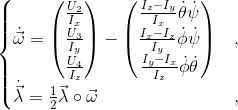
Thus, the equations of angular velocities in a coupled coordinate system:

I note that if we took into account the position of the copter, we could not introduce separate control functions, but immediately use the traction forces as them, which is more convenient and faster when calculating. In this case, the stabilization system does not have any data on the required amount of traction, therefore it is necessary to use just such controls ...
The propeller traction can be roughly described as . Then the equations can be written through the angular frequencies of the propellers, if you can directly control the frequency of the motors and know the specific b:
 where
where
 are the Euler angles.
I note that the selection of the coefficient b was done manually, by a simple selection.
It is also necessary to write the equation for the quaternion of rotation. From the properties of quaternions it follows that
 , where
  are the angular velocities in the coordinate system associated with the aircraft, in it gyroscopes measure the angular velocity [1].
Let's try to stabilize only the angles and angular velocities:

Or more

We introduce the vector of state space:
 .
.
It should be noted that if a component enters the space vector, the system ceases to be controllable. However, we can assume that
  and remove it from the state vector, thereby reducing the number of coordinates [2].

Vector Control:
 ,
,
The system is representable in standard form
 .
.
In our case
 , and
, and

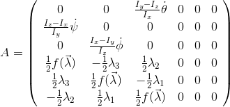
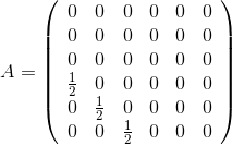
Lineariziruya system near the origin, we obtain the following matrices A and B:
 ,
,

As in the last time using linear-quadratic regulator. Let me remind you the Matlab team for its calculation:
Matrices Q and R are weight matrices. Q fines for deviating from zero, and R fines for power consumption by control.
As a result, we obtained the matrix K. In my matrix of coefficients, all off-diagonal elements were very small (of the order of 10 ^ -4) and I did not take them into account.
Let me remind you that to obtain control it is necessary to multiply the matrix K by the vector X. Of course, in the code you can not enter the concept of a matrix and just multiply each coordinate by a certain coefficient for speed.
To verify the results, a model was created in Matlab Simulink. Run it with non-zero initial conditions.

The first graph shows how the angular velocities behave, the second shows the change in the components of the quaternion. Note that the scalar quaternion value comes to unity, despite the fact that it does not enter into the equations of the linearized system. As can be seen from the graphs - the model is stabilizing.
Crazyflie uses the Free RTOS system, where all the code is divided into modules, we are interested in the sensfusion6.c and stabilizer.c code.
Fortunately, the readings of the accelerometer and gyroscope are filtered in quaternions, the problem is that the sensors on the copter are located for the + circuit. I calculated the model for the X circuit. The difference is only in the choice of controls U1 and U2.

You must add the quaternion get code in sensfusion6.c:
I did not add a separate module for the LQR controller; instead, I changed stabilizer.c. Yes, perhaps this is not the most intelligent way, but it is suitable for testing the model.
You should start by adding the variables of the current and desired position of the device, as well as the controls:
We do not indicate the desired position in q0 due to the fact that we do not need to stabilize it.
We make changes to the code for receiving commands. A copter gets an angle in degrees, it is mathematically more correct to do this:
Change the “fast” cycle (250Hz) of the stabilizer:
The selection of the coefficients was carried out empirically, since it was not possible to find out the relationship between the command sent to the motors and the force that the engine produces.
I also changed the power distribution function of the motors:
Based on the fact that the copter stabilizes its angles, we can conclude that the mathematical model is developed correctly. Unfortunately, there is still no way to get your coordinates and speeds (integration of the accelerometer gives a huge error), so the copter does not extinguish the initial speed and does not return to the initial position.
To solve this problem, MIT, for example, uses cameras and tags on its copters.
PS Unfortunately, I can’t share the model, as well as talk about the extended model with autopilot and coordinate stabilization due to the fact that this is part of my future diploma, and all diplomas are now checked for novelty and anti-plagiarism.
PPS I publish this article on the hub, and not on the new GT due to the fact that the rest of my articles of a similar subject remained on the hub.
It will cover very briefly: a simple model of angular stabilization of a quadrocopter using quaternions, linearization, building control for an object and checking it in Matlab Simulink, as well as checking on a real object. Crazyflie 1.0 will be the test subject.
Now it flies like this (at the time of filming, I did not set the control very correctly):
Building a dynamic system
We introduce 2 coordinate systems: a local one, tied to the ground, and a second one associated with the copter.

The rotation of the body is more convenient to imagine using quaternions, due to the smaller number of necessary calculations. A lot of articles have been written about them, including on the Habr. I recommend reading the book “Branets V.N., Shmyglevsky I.P. Application of quaternions in orientation problems ”, thanks to Slovak from the MathWorks Competence Center for the tip.
We use the basic law of the dynamics of rotational motion:,
 where
where  are the moments acting on the body,
 I is the inertia tensor, and
 are the angular velocities along the main axes (in a connected coordinate system).
 Thus:
 .
.By the theorem on the reduction of the inertia tensor to the principal axes of the inertia tensor can be represented as:
 .
. We define external moments through controls:,
 where
where 
Thus, the equations of angular velocities in a coupled coordinate system:

I note that if we took into account the position of the copter, we could not introduce separate control functions, but immediately use the traction forces as them, which is more convenient and faster when calculating. In this case, the stabilization system does not have any data on the required amount of traction, therefore it is necessary to use just such controls ...
The propeller traction can be roughly described as
 . Then the equations can be written through the angular frequencies of the propellers, if you can directly control the frequency of the motors and know the specific b:
 where
where  are the Euler angles.
 I note that the selection of the coefficient b was done manually, by a simple selection.
It is also necessary to write the equation for the quaternion of rotation. From the properties of quaternions it follows that
 , where
  are the angular velocities in the coordinate system associated with the aircraft, in it gyroscopes measure the angular velocity [1].
 Let's try to stabilize only the angles and angular velocities:

Or more

We introduce the vector of state space:
 .
. It should be noted that if a component enters the space vector, the
 system ceases to be controllable. However, we can assume that
  and remove it from the state vector, thereby reducing the number of coordinates [2].
Vector Control:
 ,
,The system is representable in standard form
 .
. In our case
 , and
, and
Linearization and control construction
Lineariziruya system near the origin, we obtain the following matrices A and B:
 ,
, 
As in the last time using linear-quadratic regulator. Let me remind you the Matlab team for its calculation:
[K,S,e]=lqr(A,B,Q,R)
Matrices Q and R are weight matrices. Q fines for deviating from zero, and R fines for power consumption by control.
As a result, we obtained the matrix K. In my matrix of coefficients, all off-diagonal elements were very small (of the order of 10 ^ -4) and I did not take them into account.
Let me remind you that to obtain control it is necessary to multiply the matrix K by the vector X. Of course, in the code you can not enter the concept of a matrix and just multiply each coordinate by a certain coefficient for speed.
Model check
To verify the results, a model was created in Matlab Simulink. Run it with non-zero initial conditions.

The first graph shows how the angular velocities behave, the second shows the change in the components of the quaternion. Note that the scalar quaternion value comes to unity, despite the fact that it does not enter into the equations of the linearized system. As can be seen from the graphs - the model is stabilizing.
The code
Crazyflie uses the Free RTOS system, where all the code is divided into modules, we are interested in the sensfusion6.c and stabilizer.c code.
Fortunately, the readings of the accelerometer and gyroscope are filtered in quaternions, the problem is that the sensors on the copter are located for the + circuit. I calculated the model for the X circuit. The difference is only in the choice of controls U1 and U2.

You must add the quaternion get code in sensfusion6.c:
void sensfusion6GetQuaternion(float* rq0,float* rq1,float* rq2,float* rq3){
  *rq0=q0;
  *rq1=q1;
  *rq2=q2;
  *rq3=q3;
}
I did not add a separate module for the LQR controller; instead, I changed stabilizer.c. Yes, perhaps this is not the most intelligent way, but it is suitable for testing the model.
You should start by adding the variables of the current and desired position of the device, as well as the controls:
static float q0Actual;
static float q1Actual;
static float q2Actual;
static float q3Actual;
static float q1Desired;
static float q2Desired;
static float q3Desired;
int16_t  actuatorU1;
int16_t  actuatorU2;
int16_t  actuatorU3;
We do not indicate the desired position in q0 due to the fact that we do not need to stabilize it.
We make changes to the code for receiving commands. A copter gets an angle in degrees, it is mathematically more correct to do this:
сommanderGetRPY(&q1Desired, &q2Desired, &q3Desired);
      q1Desired=cos((-q1Desired/2+90)*0.01745);//*3.14/180/2;
      q2Desired=cos((q2Desired/2+90)*0.01745);
      q3Desired=cos((q3Desired/2+90)*0.01745);
Change the “fast” cycle (250Hz) of the stabilizer:
sensfusion6UpdateQ(gyro.x, gyro.y, gyro.z, acc.x, acc.y, acc.z, FUSION_UPDATE_DT);
sensfusion6GetEulerRPY(&eulerRollActual, &eulerPitchActual, &eulerYawActual);
sensfusion6GetQuaternion(&q0Actual, &q1Actual,&q2Actual,&q3Actual);
sensfusion6UpdateP(FUSION_UPDATE_DT);
sensfusion6UpdateV(acc.x, acc.y, acc.z, FUSION_UPDATE_DT);
actuatorU1=50*(1*(-gyro.x)+245*(q1Actual-q1Desired));
actuatorU2=50*(1*(gyro.y)-200*(q2Actual-q2Desired));
actuatorU3=50*(1.5*(gyro.z)+0*(q3Actual-q3Desired));
The selection of the coefficients was carried out empirically, since it was not possible to find out the relationship between the command sent to the motors and the force that the engine produces.
I also changed the power distribution function of the motors:
static void distributePower(const uint16_t thrust, const int16_t u2, const int16_t u3, const int16_t u4)
{
  motorPowerM1=limitThrust((thrust/4+u3/2+u4/4)*5);
  motorPowerM2=limitThrust((thrust/4-u2/2-u4/4)*5);
  motorPowerM3=limitThrust((thrust/4-u3/2+u4/4)*5);
  motorPowerM4=limitThrust((thrust/4+u2/2-u4/4)*5);
  motorsSetRatio(MOTOR_M1, motorPowerM1);
  motorsSetRatio(MOTOR_M2, motorPowerM2);
  motorsSetRatio(MOTOR_M3, motorPowerM3);
  motorsSetRatio(MOTOR_M4, motorPowerM4);
}
Conclusion
Based on the fact that the copter stabilizes its angles, we can conclude that the mathematical model is developed correctly. Unfortunately, there is still no way to get your coordinates and speeds (integration of the accelerometer gives a huge error), so the copter does not extinguish the initial speed and does not return to the initial position.
To solve this problem, MIT, for example, uses cameras and tags on its copters.
Additional materials and sources
- Branets V.N., Shmyglevsky I.P. “The use of quaternions in orientation problems”
- Yaguang Yang "Analytic LQR Design for Spacecraft Control System Based on Quaternion Model"
- Branch modified firmware on github
PS Unfortunately, I can’t share the model, as well as talk about the extended model with autopilot and coordinate stabilization due to the fact that this is part of my future diploma, and all diplomas are now checked for novelty and anti-plagiarism.
PPS I publish this article on the hub, and not on the new GT due to the fact that the rest of my articles of a similar subject remained on the hub.
