Making a modular multi-channel ADC
In various projects, it is often necessary to monitor many parameters that are represented by analog values. Of course, a microcontroller is often enough, but sometimes the processing algorithm is too complicated for it and the use of a full-fledged computer is required. In addition, it is much easier to organize log saving and beautiful data visualization on it. In this case, either a ready-made industrial solution is taken (which, of course, is expensive, but is often redundant), or something home-made is done. In the most common case, it could be an Arduino board with an infinite loop from analogRead and serial.write. If there is a lot of input data (more than analog inputs), then you will need several boards, figure out how to correctly interrogate them from a computer, etc. In many cases, the solution I developed (the
To understand whether this solution is suitable for you, I suggest that you familiarize yourself with its characteristics:
Maximum number of channels: 44;
Sampling Rate: 1000 Hertz;
Resolution: 8 bit.
Characteristics are rather mediocre, but for many tasks they may be suitable. This is not an oscilloscope, but a sensor interrogation system. Moreover, on her example, you can get acquainted with the use of USART for other purposes.
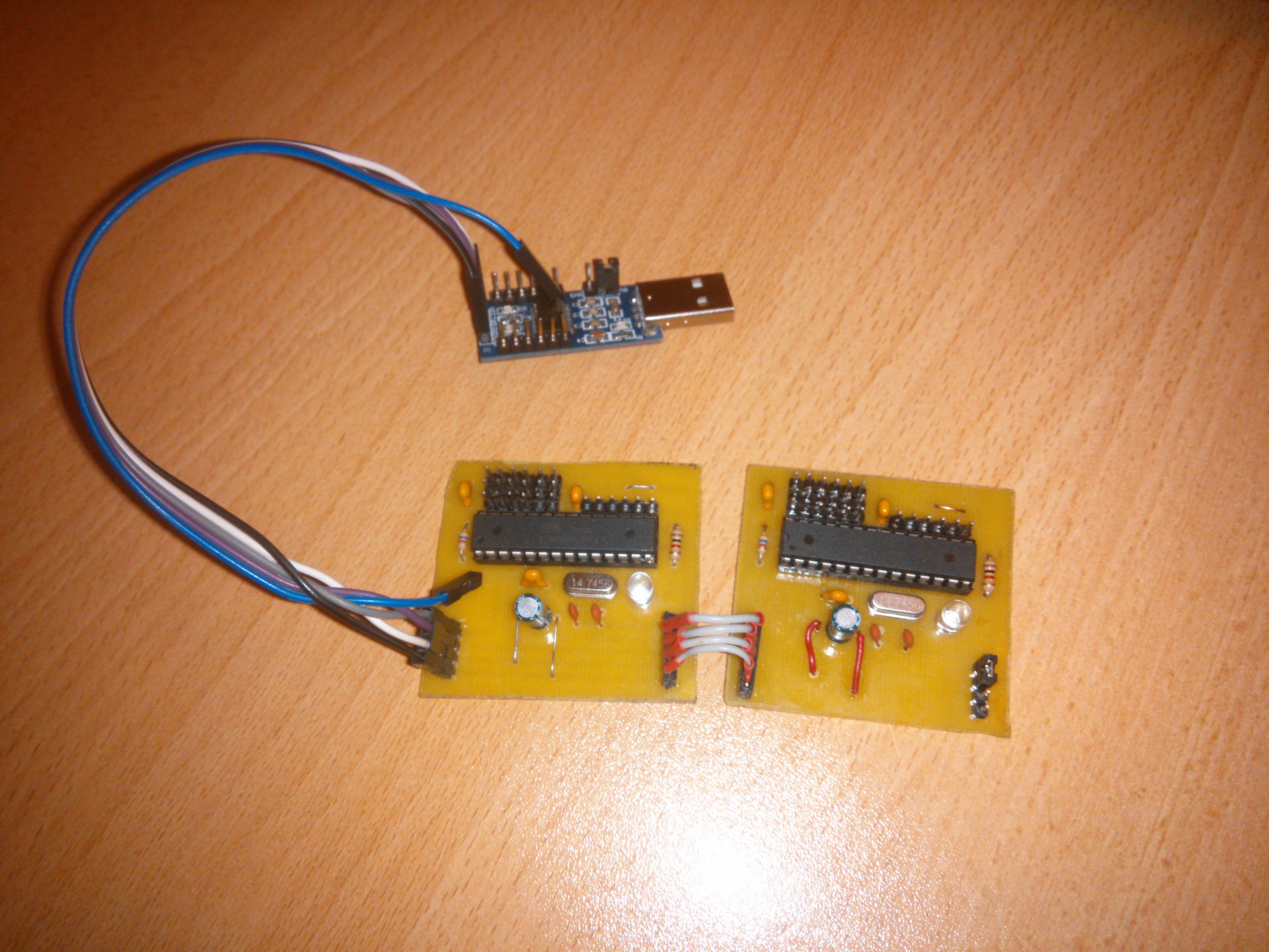
The system consists of separate ADC modules based on the ATMEGA8 microcontroller (you can use another MK of the AVR family with the ADC and the USART hardware module if you change the firmware a little). There can be one or several modules, each provides 6 or 8 ADCs depending on the case of the microcontroller (the output version has 6 ADCs, and for surface mounting 8), only the total number of channels should not exceed 44. The main feature is that regardless of the number of modules requires only one USART from the computer side (it can be a USB adapter or a hardware COM port). This is achieved due to the fact that the USARTs of all microcontrollers are connected in series (RX of one to TX of the other), and the RX and TX pins of the last in the chain are already connected to the computer.
Here it should be noted that the resolution of my ADC is not exactly 8 bits - maybe only 255 gradations instead of 256. The value 0xFF is reserved for a special purpose. If the microcontroller receives it, it starts issuing a value each time from the next channel of its ADC, and when they end, it relayes 0xFF further down the chain. If a value other than 0xFF arrives at the USART input, the microcircuit simply sends the byte further. Thus, passing one arbitrary value and 44 0xFF, you can get values from all channels of all ADCs (if the ADC is less, then the extra channels will be 0xFF). An arbitrary value is needed so that all modules reset the pointer to the current ADC channel, which must be transmitted when 0xFF is received. In reality, it is more convenient to transmit 45 0xFF in order to reliably determine the end of reception (if you received 0xFF, then the channels have ended).
The circuit diagram does not contain very many details:

The program for AVR looks extremely simple and takes up slightly less than 300 bytes of memory:
In the repository on GitHub you can find the KiCad circuit and circuit board files, as well as an example program for a computer that reads data from this system and outputs them in CSV format.
It’s convenient that the serial port is used almost to the limit of its capabilities, so it doesn’t have to worry about data synchronization (I just send 1000 commands to read the ADC every second) - if we transfer 46 kilobytes of data every second at a speed of 460800 bits per second, then you can Be completely sure that blocks of 46 bytes of data (one measurement) will arrive every millisecond (although buffering with the OS kernel and USB adapter will, of course, introduce a delay, but measurements will always be performed at the right frequency).
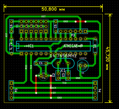
The circuit board was designed at KiCad:
All boards are connected in a chain, at the last board RX and TX are connected by a jumper.
The quality of the ADC can be estimated from this image of a 10 Hz saw:
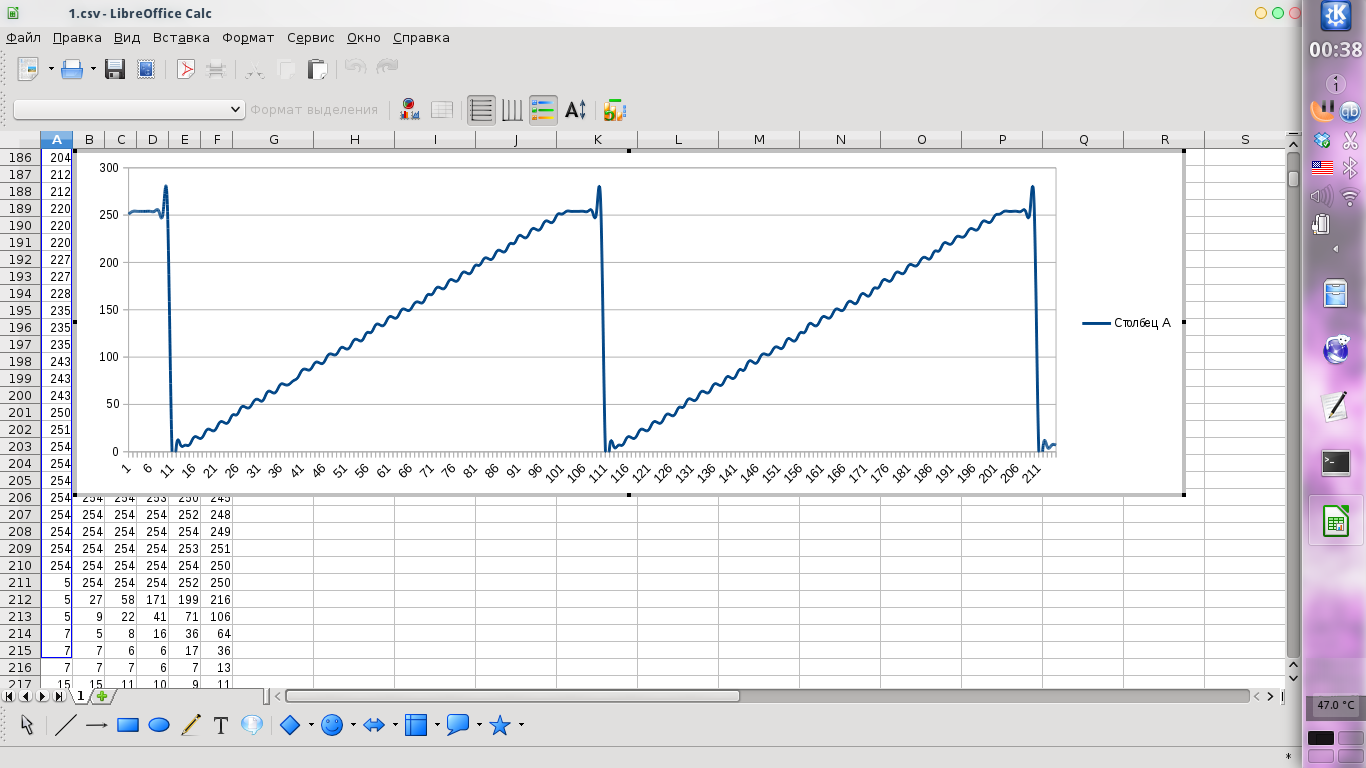
For comparison, the image from the DS203 oscilloscope (it also acts as a generator):

Unfortunately, I do not have a better signal source, but for low-frequency signals my system should work.
It should be noted that not every USART-USB converter provides a speed of 460800 bps with a full channel load. The CP2102-based converter made me look for an error in my own code for a long time, until I tried FT232. Also, a loss of about 0.17% of data is observed (measures were taken in the computer program so that data synchronization was not lost). Most likely this is due to a bad USART line, or a flaw in the program. In general, for 90% of applications it should not be critical, but most likely it is not worth putting on nuclear power plants.
And finally, I’ll say that the cost of one module is about 50-60 rubles if you order all the parts from China, so the solution should be attractive enough.
To understand whether this solution is suitable for you, I suggest that you familiarize yourself with its characteristics:
Maximum number of channels: 44;
Sampling Rate: 1000 Hertz;
Resolution: 8 bit.
Characteristics are rather mediocre, but for many tasks they may be suitable. This is not an oscilloscope, but a sensor interrogation system. Moreover, on her example, you can get acquainted with the use of USART for other purposes.
The system consists of separate ADC modules based on the ATMEGA8 microcontroller (you can use another MK of the AVR family with the ADC and the USART hardware module if you change the firmware a little). There can be one or several modules, each provides 6 or 8 ADCs depending on the case of the microcontroller (the output version has 6 ADCs, and for surface mounting 8), only the total number of channels should not exceed 44. The main feature is that regardless of the number of modules requires only one USART from the computer side (it can be a USB adapter or a hardware COM port). This is achieved due to the fact that the USARTs of all microcontrollers are connected in series (RX of one to TX of the other), and the RX and TX pins of the last in the chain are already connected to the computer.
Here it should be noted that the resolution of my ADC is not exactly 8 bits - maybe only 255 gradations instead of 256. The value 0xFF is reserved for a special purpose. If the microcontroller receives it, it starts issuing a value each time from the next channel of its ADC, and when they end, it relayes 0xFF further down the chain. If a value other than 0xFF arrives at the USART input, the microcircuit simply sends the byte further. Thus, passing one arbitrary value and 44 0xFF, you can get values from all channels of all ADCs (if the ADC is less, then the extra channels will be 0xFF). An arbitrary value is needed so that all modules reset the pointer to the current ADC channel, which must be transmitted when 0xFF is received. In reality, it is more convenient to transmit 45 0xFF in order to reliably determine the end of reception (if you received 0xFF, then the channels have ended).
The circuit diagram does not contain very many details:
The program for AVR looks extremely simple and takes up slightly less than 300 bytes of memory:
#include
#include
#include
#include
// Firmware options
#define USART_BAUDRATE 460800
#define LED_PIN 1
#define ADC_COUNT 6
#define STARTUP_DELAY 1000
// Calculated UBRR value
#define UBRR (F_CPU / (16 * (uint32_t)USART_BAUDRATE) - 1)
// Global variables
uint8_t adc[ADC_COUNT]; // Buffer
uint8_t cur_in_adc; // Input byte index
uint8_t cur_out_adc; // Output byte index
// USART interrupt handler
ISR(USART_RXC_vect) {
	// Read data from USART
	uint8_t buffer = UDR;
	if (buffer == 0xFF) {
		if (cur_out_adc < ADC_COUNT) {
			// Return data byte from buffer
			UDR = adc[cur_out_adc];
			cur_out_adc++;
			// Activate led
			PORTB |= _BV(LED_PIN);
		} else {
			// Chain 0xFF
			UDR = 0xFF;
			// Deactivate led
			PORTB &= ~_BV(LED_PIN);
		}
	} else {
		// Chain data byte
		UDR = buffer;
		// Reset byte counter
		cur_out_adc = 0;
		// Deactivate led
		PORTB &= ~_BV(LED_PIN);
	}
}
// Main function
void main() {
	// Setup watchdog timer
	wdt_enable(WDTO_15MS);
	// Setup pin for led
	DDRB |= _BV(LED_PIN);
	// Blink led
	PORTB |= _BV(LED_PIN);
	for (uint8_t i = 0; i < STARTUP_DELAY / 5; i++) {
		_delay_ms(5);
		wdt_reset();
	}
	PORTB &= ~_BV(LED_PIN);
	// Setup ADC
	ADMUX = _BV(REFS1) | _BV(REFS0) | _BV(ADLAR);
	ADCSRA = _BV(ADEN) | _BV(ADPS2) | _BV(ADPS1) | _BV(ADPS0);
	// Setup USART
	UBRRL = UBRR & 0xFF;
	UBRRH = UBRR >> 8;
	UCSRA = 0;
	UCSRB = _BV(RXCIE) | _BV(RXEN) | _BV(TXEN);
	UCSRC = _BV(URSEL) | _BV(UCSZ1) | _BV(UCSZ0);
	// Enable interrupts
	sei();
	// Main loop
	while (1) {
		// Reset watchdog timer
		wdt_reset();
		// Select ADC channel
		ADMUX = _BV(REFS1) | _BV(REFS0) | _BV(ADLAR) | cur_in_adc;
		// Start conversion and wait until it performed
		ADCSRA |= _BV(ADIF) | _BV(ADSC);
		while (ADCSRA & _BV(ADSC));
		// Put value from ADC to buffer
		uint8_t value = ADCH;
		adc[cur_in_adc] = (value != 0xFF) ? value : 0xFE;
		// Switch to next channel
		cur_in_adc++;
		if (cur_in_adc >= ADC_COUNT) {
			cur_in_adc = 0;
		}
	}
}
In the repository on GitHub you can find the KiCad circuit and circuit board files, as well as an example program for a computer that reads data from this system and outputs them in CSV format.
It’s convenient that the serial port is used almost to the limit of its capabilities, so it doesn’t have to worry about data synchronization (I just send 1000 commands to read the ADC every second) - if we transfer 46 kilobytes of data every second at a speed of 460800 bits per second, then you can Be completely sure that blocks of 46 bytes of data (one measurement) will arrive every millisecond (although buffering with the OS kernel and USB adapter will, of course, introduce a delay, but measurements will always be performed at the right frequency).
The circuit board was designed at KiCad:
All boards are connected in a chain, at the last board RX and TX are connected by a jumper.
The quality of the ADC can be estimated from this image of a 10 Hz saw:
For comparison, the image from the DS203 oscilloscope (it also acts as a generator):
Unfortunately, I do not have a better signal source, but for low-frequency signals my system should work.
It should be noted that not every USART-USB converter provides a speed of 460800 bps with a full channel load. The CP2102-based converter made me look for an error in my own code for a long time, until I tried FT232. Also, a loss of about 0.17% of data is observed (measures were taken in the computer program so that data synchronization was not lost). Most likely this is due to a bad USART line, or a flaw in the program. In general, for 90% of applications it should not be critical, but most likely it is not worth putting on nuclear power plants.
And finally, I’ll say that the cost of one module is about 50-60 rubles if you order all the parts from China, so the solution should be attractive enough.