Background
Like many habruppeli, possessing some skills and good imagination, somehow stumbled upon a site, then it still hung on the people, and was dedicated to pairing homemade devices with a PC. It was then that a seed of unbridled interest arose in order to do something and manage it from a computer. Then, of course, it all started with the lpt port of the printer and gradually grew to a com port and eventually to usb. Everything would be fine until I came across a site dedicated to creating a smart home system. Then I realized that I was really interested. Let's skip the long and interesting story and go straight to the topic. I am writing this article as an amateur, not a pro, and I hope it helps you create your network from scratch, or draw useful experience for your network. In this article I want to describe the creation of my 1wire network with scratch, including all stages of construction and useful tips.
- Design, printing, etching, tinning and soldering of the printed circuit board;
- Installation of 1wire industrial bus;
- Software and hardware management and monitoring.
So, the easiest way to create a network is a network wizard and any device running on this protocol. Typically, you have to do the device yourself (except for temperature sensors) or buy for a lot of money. For a beginner, you need a master of the usb / com network and a pair of temperature sensors. All this can be connected using the standard power supply of the port, the so-called stray power, or connected to an additional power supply in case of a large number of devices and the length of the loop. For example, I use the ready-made network master on the usb port (DS9490R):
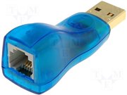
As you can see, one end is inserted into the usb port of the serving system, it can be a computer or a wi-fi router, or unicameral solutions. The other end is the “mother” of the RJ-11 connector (standard telephone jack). I also use calibrated temperature sensors (DS18B20 +):
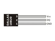
I also use and plan to use:
- Calibrated temperature sensors (DS18B20 +);
- 4-channel Analog-to-Digital Converters (DS2450S);
- 8-channel input / output chips (DS2408 +).
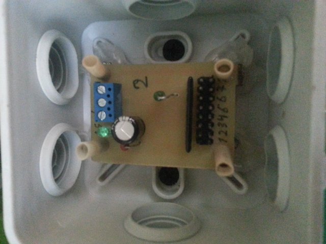
Unfortunately, these are all chips, I had to create boards myself, especially in the manual for each chip you can find standard usage schemes with element ratings and connection options. Here are a few boards that I have already created. The boards do not pull on the five, so you should not literally copy them: VANIL-1880: (a small board of 8 inputs / outputs for any needs - reed switches, motion sensors, control of low-current systems, etc. ...)
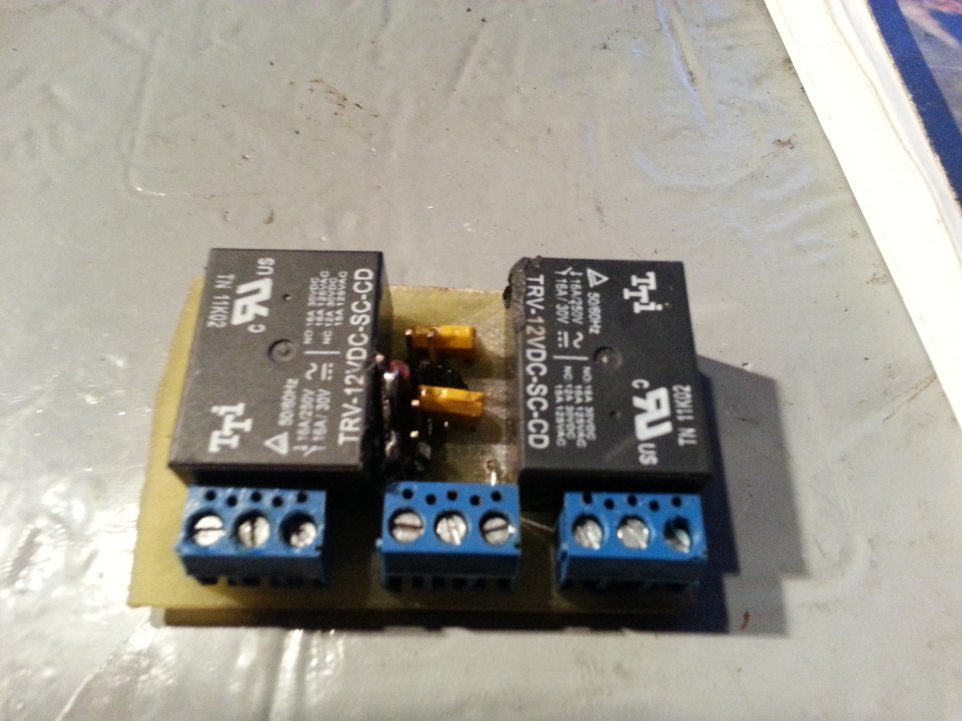
VANIL-1853S (board with 5 inputs / outputs and 3 triacs for connecting high-voltage devices, I did not use radiators, therefore only through relays or magnetic starters, the range of applications is very wide):
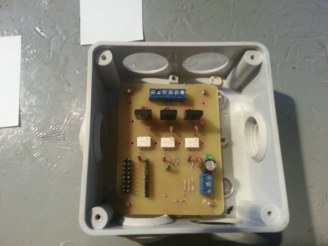
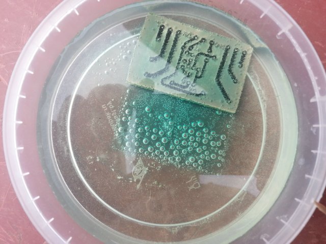
As you can see, everything is neatly placed in standard plastic soldered boxes using screws and hot melt adhesive. At the moment I use a network of only 20 temperature sensors, to monitor the temperature in the country, everything is connected to the server on Gentoo Linux. Software for working with the owfs network. This first part of the article is intended for familiarization, the rest of the detailed information will be added later and at the request of the habrowser. I would also like to know your experience and listen to criticism. About etching boards: today I switched from ferric chloride to salt + citric acid + hydrogen peroxide. While there is no information about the quality of etching, the board is still etched:
The composition is this: 100ml peroxide, 30 grams of citric acid and 5-6 grams of table salt. And so after a while I want to add to the article, and first of all I will say that I liked the new method of etching the boards, a little longer but the effect is not worse than from ferric chloride. I etched a board to control the liquid level in a well with technical water, there are two sensors installed, one just above the nose and the second at the very top, there is also a semi-automatic control, start and stop manually, indicators in the form of bulbs that indicate work system. Liquid level sensors are usually expensive, so I made them myself, unfortunately there is no way to photograph, they are already immersed in the well. But with pleasure I will describe the components and design.
List of used components:
- Reed switch for metal doors, round, sealed insides
- A piece of HDPE pipe about 10-15 cm
- Silicone, for roofing
- Eraser from a soldered box with a hole
- A piece of UTP wire, 4-core (less was not) the desired length
- Float material, I used polystyrene
Here are the photographs of the components (this sensor implementation has not yet been tested by time): also a lay tool for cutting PND is attached:


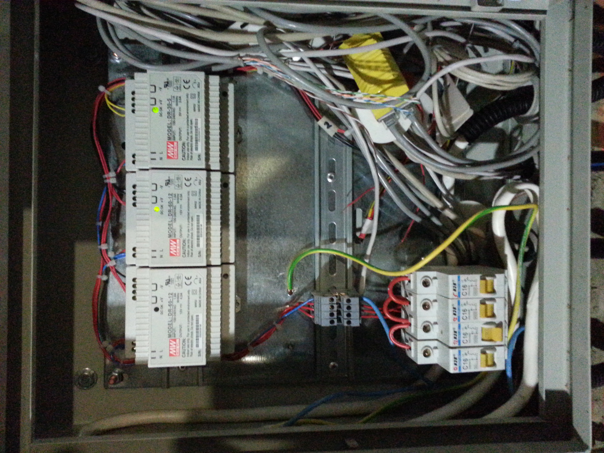
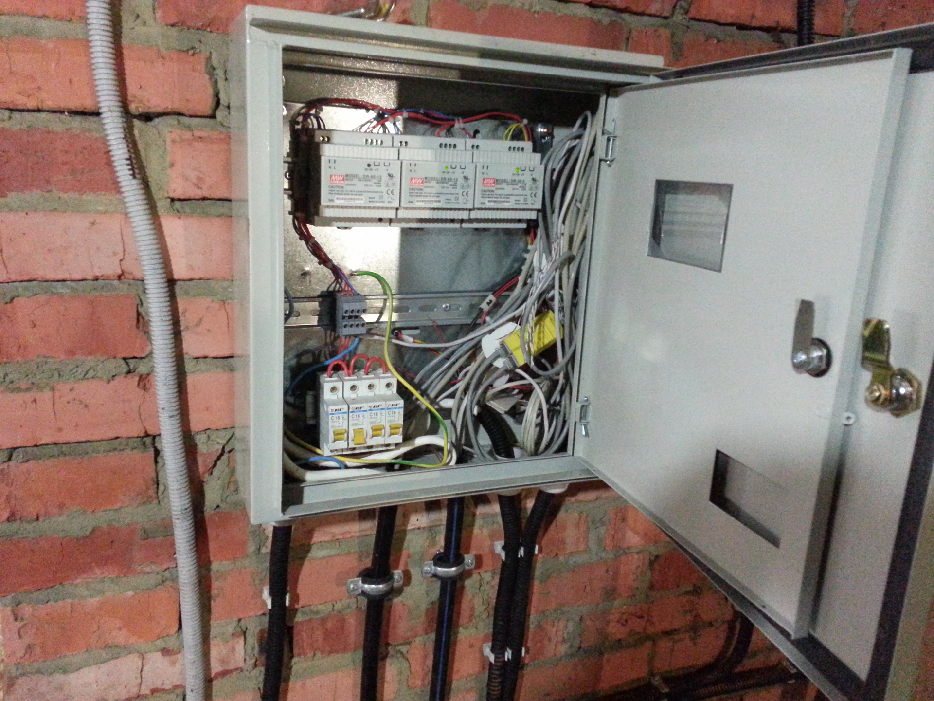
This system does not work directly with 1wire, you can only read the status of its operation. Which is actually enough, although by simply connecting to one of the 8 inputs / outputs, you can simulate the well filling and start pumping from the computer. Everything is mounted in a sealed box, including power supplies for the DIN rail. I
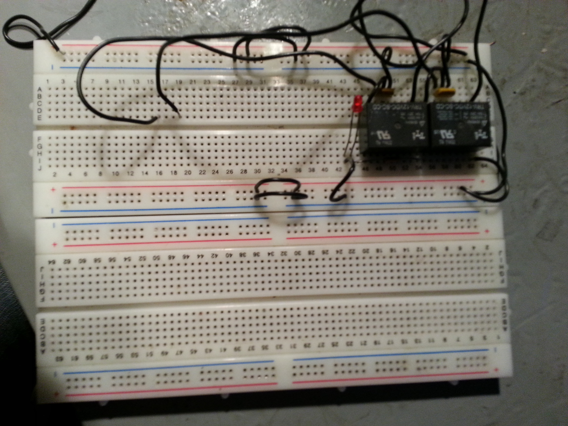
also advise newcomers to buy a debug board, it looks like this:
Here are the photos of the box:

I use the SLayer5 program for designing boards. The only thing I have not put here is the layout of all the boards, as well as those that I have not yet implemented. But this topic is not the final product, it’s just my experience, and I’m going to develop it. Now the silent software part, I did everything under Gentoo Linux therefore, the kernel had to build fuse for owfs to work, if you know Linux, then it will be easy for you to include a couple of new items when compiling the kernel. This is for the sofa. I’m asking for sensors every 15 minutes through the crowns, then I’ll print the charts by 4, that is, the readings in an hour. I’m sorry I can’t fit everything in this article, so I will write the rest in the next part, look for the 1wire tag