Automatically shutdown computer peripherals
I want to talk about a device that automatically disconnects all peripherals that are connected to the system unit.
For those who have fast Internet, you can immediately watch the video, which explains how the automatic shutdown of peripherals works and how to implement this device:
Everyone else welcome under cat.
A device for disconnecting peripherals is a set of the following components:
1. “Pilot” or extension cord for connecting peripherals.
2. Relay operating on a voltage of 5 volts.
3. A wire for connecting a relay, ie a wire with a usb connector on one end.
4. Skillful pens, where without them.
So, let's start with the selection of the relay, I chose this: The
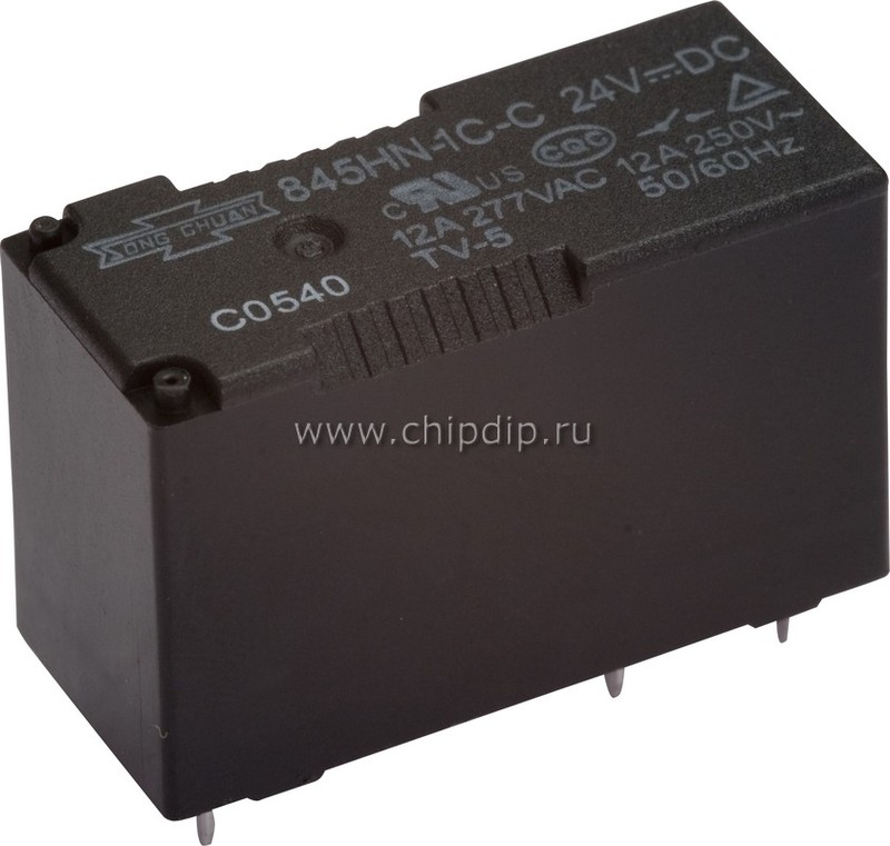
full name of this relay for ordering is 845HN-1C-C 05VDC, i.e. you need to pay attention to the fact that in the picture we have a version of the relay with 24 volts, we need a relay with 5 volts.
Next, we need a wire with a USB connector, I had a wire from a laptop mouse, you can pick up something like that or just buy the cheapest mouse and pull a wire from it.
In addition, it is necessary to prepare the following tools and materials:
1. Soldering iron
2. Multi-tester
3. Tin and rosin
4. Phase screwdriver (optional, I will explain later why)
So, we begin work on the manufacture of a device to automatically turn off the computer’s peripherals.
To begin with,
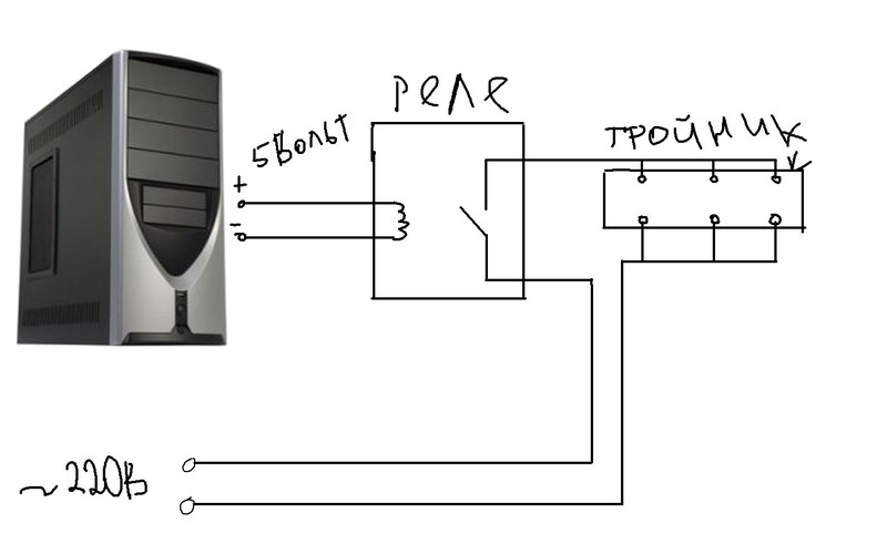
we’ll get acquainted with the device’s diagram: As we can see from this diagram, one of the 220-volt wires goes directly to the extension cord contacts, the other we break and let through the relay.
I hope there will be no problems with disassembling the extension cord.
For those who do not quite understand how the relay works, I want to show the following picture: The

relay is a coil on which a wire is wound (shown in yellow in the figure), in the middle of the coil there is an iron core. There is a so-called anchor above the coil, i.e. metal rocker. The passive state of the relay, i.e. This is the condition when power to the relay is not supplied.
What happens when we power the coil? The relay core is magnetized and draws the armature to itself. As a result of this, the anchor squeezes out contacts that close together, this relay position is shown at the bottom of the picture.
We need information from which Usb contacts to take power for our relay. The following image will help us with this:
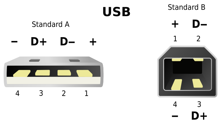
We need two extreme contacts, plus and minus to activate our relay.
On the relay itself, we need to find the contacts, they look something like this:

If you turn the relay upside down, you will see the image as in the picture above. To two legs that are closed by a wavy line (coil designation), we connect power from a USB cable. Then we need to find two contacts, one of them looks like in the picture, with a diagonal line - this is the first wire to connect the 220 volt wire. We connect the second wire to the contact, which will conditionally be connected if the diagonal line is thrown to the right. Using a phase screwdriver, you can connect a named phase wire to the relay.
The sequence of work is simple:
Notes
PS. If someone knows how to ensure usb power off on the connectors on the rear panel after turning off the computer, write in the comments.
Upgrade
For someone whose USB power does not turn off, take 12 volts per molecule from the system unit.
Relay I think this is suitable - www.gsm.msk.ru/catalog.html?itemid=46 . For safety reasons, you can put such a relay with two changeover contacts - www.21vek-220v.ru/goods2/rele-s-2-perekidnymi-kontaktami-12v-dc-8a and put both pilot wires through the relay.
For those who have fast Internet, you can immediately watch the video, which explains how the automatic shutdown of peripherals works and how to implement this device:
Everyone else welcome under cat.
Components
A device for disconnecting peripherals is a set of the following components:
1. “Pilot” or extension cord for connecting peripherals.
2. Relay operating on a voltage of 5 volts.
3. A wire for connecting a relay, ie a wire with a usb connector on one end.
4. Skillful pens, where without them.
Materials and tools
So, let's start with the selection of the relay, I chose this: The
full name of this relay for ordering is 845HN-1C-C 05VDC, i.e. you need to pay attention to the fact that in the picture we have a version of the relay with 24 volts, we need a relay with 5 volts.
Next, we need a wire with a USB connector, I had a wire from a laptop mouse, you can pick up something like that or just buy the cheapest mouse and pull a wire from it.
In addition, it is necessary to prepare the following tools and materials:
1. Soldering iron
2. Multi-tester
3. Tin and rosin
4. Phase screwdriver (optional, I will explain later why)
Assembly
So, we begin work on the manufacture of a device to automatically turn off the computer’s peripherals.
To begin with,
we’ll get acquainted with the device’s diagram: As we can see from this diagram, one of the 220-volt wires goes directly to the extension cord contacts, the other we break and let through the relay.
I hope there will be no problems with disassembling the extension cord.
For those who do not quite understand how the relay works, I want to show the following picture: The
relay is a coil on which a wire is wound (shown in yellow in the figure), in the middle of the coil there is an iron core. There is a so-called anchor above the coil, i.e. metal rocker. The passive state of the relay, i.e. This is the condition when power to the relay is not supplied.
What happens when we power the coil? The relay core is magnetized and draws the armature to itself. As a result of this, the anchor squeezes out contacts that close together, this relay position is shown at the bottom of the picture.
We need information from which Usb contacts to take power for our relay. The following image will help us with this:
We need two extreme contacts, plus and minus to activate our relay.
On the relay itself, we need to find the contacts, they look something like this:
If you turn the relay upside down, you will see the image as in the picture above. To two legs that are closed by a wavy line (coil designation), we connect power from a USB cable. Then we need to find two contacts, one of them looks like in the picture, with a diagonal line - this is the first wire to connect the 220 volt wire. We connect the second wire to the contact, which will conditionally be connected if the diagonal line is thrown to the right. Using a phase screwdriver, you can connect a named phase wire to the relay.
The sequence of work is simple:
- In a usb wire we determine the necessary wires using a tester
- We open the extension cord
- Cut one of the wires inside the extension cord
- We solder the usb wire to the relay, isolate the soldering places using a heat shrink tube
- We solder 220 volt wires to the relay, carefully isolate the solder points using a heat shrink tube
- Usb and 220 volt wires can be fixed to the relay housing using tape or tape to prevent soldering
- We test the device for operability, note that the Usb wire must be connected to the front panel, because there is voltage on the rear panel Usb connectors even after turning off the computer
- We fix the relay in the case, I used hot glue
- Putting the pilot together
- We plug the pilot into the socket, check with a phase screwdriver that we have broken the phase wire, if this is not so, just turn the plug 180 degrees
Notes
- Do not exceed the recommended load on the extension cord made, the load is calculated as the operating voltage indicated on the relay multiplied by the current strength, in our case 220V * 12A = 3000 W or 3 kW.
- Remember that you break only one wire in the extension cord, if you broke the neutral wire, operations with the extension cord supposedly turned off can be life-threatening. If you want to make a safer extension cord, look for a relay with two changeover contacts.
- Alternatively, if you want to make a button for direct use of the extension cord (i.e., without activation from Usb), you need to connect it as follows (circled in red):

PS. If someone knows how to ensure usb power off on the connectors on the rear panel after turning off the computer, write in the comments.
Upgrade
For someone whose USB power does not turn off, take 12 volts per molecule from the system unit.
Relay I think this is suitable - www.gsm.msk.ru/catalog.html?itemid=46 . For safety reasons, you can put such a relay with two changeover contacts - www.21vek-220v.ru/goods2/rele-s-2-perekidnymi-kontaktami-12v-dc-8a and put both pilot wires through the relay.