Clever watering of a flower on the Attiny13A microcontroller
Good day, Habrausers. Sometimes in life there are times when you want to do something with your own hands. Programming and electronics are a very fun way to spend time, and a flower watering system can even be beneficial. I tried to make everything simple and detailed to explain each stage. I hope this will be useful and exciting for both readers and those who decide to treat themselves and do something like that.
I bring to your attention a device for automatic watering of flowers based on the Attiny13a microcontroller, details under the cut.
Let's start with the technical specifications
- We will make a device that can water indoor plants without human intervention for at least 5 days.
- The device must take into account soil moisture.
- The cost of the device should not exceed 1000r.
Element base selection
I blinded him from what was
The choice of the microcontroller was obvious, I had Attiny13А , and I took it, he has 1Kb of memory for the program, but oh well, that’s enough. I got it for 115 rubles in a retail electronics store.
Attiny13А datasheet

Figure 1 (microcontroller Attiny13А)
Microcontroller, contains the basic logic of work.
For an analog sensor:
Pause between irrigation for 3 hours, if the signal from the humidity sensor decreases (to 2V or even 1V), the duration of the break is reduced, the minimum break is 1 hour. The watering cycle is 6-12 seconds, the first 6 seconds the watering will be in any case, then when the signal from the 3V humidity sensor is exceeded, watering stops, or lasts 12 seconds if the humidity is not reached. When you click on the (reset) button, watering occurs right now.
For a sensor with a comparator (high signal at low humidity):
Pause between irrigation for 3 hours, if the signal from the humidity sensor is higher than 3V, the duration of the break is reduced, the minimum break is 1 hour. The watering cycle is 6-12 seconds, the first 6 seconds the watering will be in any case, then when the signal from the humidity sensor decreases less than 3V, the watering stops, or it lasts 12 seconds if the humidity is not reached. When you click on the (reset) button, watering occurs right now.
ULN2003A

Figure 2 (ULN2003A chip)
Darlington transistor assembly is needed in order to control the relay and blink the LED. On the controller, the current from the legs is very small, 20mA, maybe even less, and the relay needs 100mA and protection against inductive load by a diode with this circuit is unnecessary, because everything is already provided inside. Bought for 20 rubles.
Soil moisture sensor (power supply 5V, threshold output), 150 r

Figure 3 (soil moisture sensor with comparator)
It works like this: twist the resistor, set it to the desired humidity.
If the humidity is above the threshold, it gives a low level, if lower, then high.
Soil moisture sensor (power 5V, analog output), 230 rubles.

Figure 3_1 (analog soil moisture sensor)
And this one works like this: it produces an analog signal from small at low humidity to large at high (maximum 4.2V with 5V supply, current consumption 35mA).
There are also those in which the relay from the comparator is triggered.
Relays with control voltage 5V 200mW, switching current DC 5A 12V or more, I used this one - TR99-5VDC-SB-CD. 90 rub

Figure 4 (relay TR99-5VDC-SB-CD)
(DC-DC 6-36V / 5V 2000mA and power supply for 12V 5A) or a battery from a 4.2V phone with constantly on charging. I used a Philips x100 phone for power, which crashed the screen, a usb - miniusb wire is suitable for charging it. This is the most expensive item, the phone cost 1200r new, but because Because you only need a charging function, you can buy it on the market for a lot of second-hand for 300 rubles.
He will be careful, the controller and the pump can discharge the battery to 3V, the phone at 3.2V and below will think that the battery is dead, and the phone will stop charging it.
Instead of a phone, you can connect a charging controller, the discharge is not terrible with it, it even charges a battery that is discharged at 0. It costs 59 rubles to dx, and you still need a battery.

Figure 5 (1A Lithium Battery Charger)
Button, when pressed, emergency watering will occur.

Figure 6 (button)
Diode for protection against incorrect switching (optional).
Capacitors to taste (3300 mkF for operation from the mobile phone’s battery so that when the motor is switched on, the drawdown does not restart, 0.1-200 mkF in parallel with each consumer to suppress interference).
Resistors (10k for power supply to Reset, 0.2k-0.3k current-limiting for LED).
A glass washer pump for a VAZ (the cheapest, along with a tube, a stick and clamps for fastening a tube, a water tank). There is one important point, before throwing it into the water, you need to cover all the holes through which the water can reach the motochik or contacts, seal it, leaving only those through which the water enters and exits. Of course, you can quit it, it will even work, but it will last longer if you seal it.

Figure 7 (VAZ washer pump in a yellow bucket of water)
The board is a breadboard, or with ready-made tracks and holes for parts. If someone draws a board and attaches it in the comments, it will be great, I used the mock-up.

Figure 8 (breadboard)
To program the controller, you will need the following software: PonyProg2000, LPT programmer (or another one), hex firmware, which is attached.
If you want to correct the source and compile your hex, then you need another compiler, for example CV AVR.
Work order
First you need to prepare the controller for programming, for this you need to output the legs for programming on the programmer, according to the controller datasheet and lpt programmer.
Like this:

Figure 9 (foot controller for programming)

Figure 9_1 (general view of the programmer)

Figure 10 (lpt programmer)
The program for the controller on C (option with an analog humidity sensor 0-5V)
#define F_CPU 1200000UL
#include
#include
#define PUMP PORTB.0           //Выход на насос
#define LED PORTB.1              //Выход на светодиод
#define MIN_WORKSEC 6       //Минимальное время полива в секундах
#define WORKSEC 12              //Максимальное время полива в секундах
#define DELAYSEC 10800      //Максимальное время Паузы между поливами в секундах
#define ADC_VREF_TYPE 0x00
// Read the AD conversion result
unsigned int read_adc(unsigned char adc_input)
{
ADMUX=adc_input | (ADC_VREF_TYPE & 0xff);
// Delay needed for the stabilization of the ADC input voltage
delay_us(10);
// Start the AD conversion
ADCSRA|=0x40;
// Wait for the AD conversion to complete
while ((ADCSRA & 0x10)==0);
ADCSRA|=0x10;
return ADCW;
}
// Declare your global variables here
void main(void)
{
// Declare your local variables here
int i=0, led_delay=0;
float humidity=0;
unsigned int flagreset=0;
if(MCUSR==0x02)
{
    flagreset=1;
}
MCUSR = 0x00;
// Crystal Oscillator division factor: 8
#pragma optsize-
CLKPR=0x80;
CLKPR=0x03;
#ifdef _OPTIMIZE_SIZE_
#pragma optsize+
#endif
// Input/Output Ports initialization
// Port B initialization
// Func5=In Func4=In Func3=In Func2=In Func1=Out Func0=Out
// State5=T State4=T State3=T State2=T State1=0 State0=0
PORTB=0x00;
DDRB=0x03;
// Timer/Counter 0 initialization
// Clock source: System Clock
// Clock value: Timer 0 Stopped
// Mode: Normal top=FFh
// OC0A output: Disconnected
// OC0B output: Disconnected
TCCR0A=0x00;
TCCR0B=0x00;
TCNT0=0x00;
OCR0A=0x00;
OCR0B=0x00;
// External Interrupt(s) initialization
// INT0: Off
// Interrupt on any change on pins PCINT0-5: Off
GIMSK=0x00;
MCUCR=0x00;
// Timer/Counter 0 Interrupt(s) initialization
TIMSK0=0x04;
// Analog Comparator initialization
// Analog Comparator: Off
ACSR=0x80;
ADCSRB=0x00;
// ADC initialization
// ADC Clock frequency: 75,000 kHz
// ADC Bandgap Voltage Reference: Off
// ADC Auto Trigger Source: Free Running
// Digital input buffers on ADC0: On, ADC1: On, ADC2: On, ADC3: On
DIDR0&=0x03;
DIDR0|=0x00;
ADMUX=ADC_VREF_TYPE & 0xff;
ADCSRA=0xA1;
ADCSRB&=0xF8;
// Global enable interrupts
#asm("sei")
while (1)
      {
         PUMP=0;
         LED=1;
         delay_ms(5000);
         LED=0;
         if(flagreset == 1)
         {
            PUMP=1;
            for(i=0; iMIN_WORKSEC)
                {
                    humidity = read_adc(2)/204;
                    if(humidity>3)
                    {
                        PUMP=0;
                    }
                }
            }
            PUMP=0;
            flagreset=0;
         }
         led_delay = (DELAYSEC - 60)/12;
         for(i=0; i<(DELAYSEC/12); i++)
         {
            humidity = read_adc(2)/204;
            delay_ms(1000);
            LED=0;
            if(i>led_delay)
            {
                LED=1;
            }
            else
            {
                LED=0;
            }
            if(humidity<1)
            {
                delay_ms(3000);
            }
            else if(humidity<2)
            {
                delay_ms(5000);
            }
            else if(humidity<3)
            {
                delay_ms(8000);
            }
            else
            {
                delay_ms(10000);
            }
            delay_ms(150);
            LED=1;
            delay_ms(25);
            LED=0;
            delay_ms(150);
            LED=1;
            delay_ms(50);
            LED=0;
            delay_ms(100);
            if(humidity<2)
            {
                LED=1;
                delay_ms(150);
                LED=0;
            }
            else
            {
                delay_ms(550);
            }
         }
         LED=0;
         PUMP=1;
         for(i=0; iMIN_WORKSEC)
            {
              if(humidity>3)
              {
                PUMP=0;
              }
            }
         }
         PUMP=0;
      };
}
hex for ponyprog2000
:0E00000009C0FECFFDCFFCCFFBCFFACFF9CF6A

:10000E00F8CFF7CFF6CFF894EE27ECBBE5BFF8E1CB

:10001E00A4B7A77FA4BFF1BDE1BD8DE0A2E0ED9333

:10002E008A95E9F780E4A0E6ED938A95E9F7EFE982

:10003E00EDBFC0E70DC0E881E7B984E08A95F1F71E

:10004E00369A349BFECF349AE4B1F5B121960895D9

:10005E002497E0E0E883E983EA83EB83AFD020E0E6

:10006E0030E040E050E0E4B7E23011F441E050E01F

:10007E00E0E0E4BFE0E8E6BDE3E0E6BDE0E0E8BBDB

:10008E00E3E0E7BBE0E0EFBDE3BFE2BFE6BFE9BD03

:10009E00EBBFE5BFE4E0E9BFE0E8E8B9E0E0E3B9D3

:1000AE00E4B3E370E4BBE4B3E4BBE0E0E7B9E1EA58

:1000BE00E6B9E3B1E87FE3B97894C098C19AE8E86D

:1000CE00F3E17FD0C198E1E0F0E0E417F507C1F469

:1000DE00C09A74D00C30E0E01E077CF475D0073067

:1000EE00E0E01E073CF073D07FD080D009F008F41A

:1000FE0001C0C0980F5F1F4FEDCFC09840E050E099

:10010E002FE733E05BD00438E3E01E07F4F55FD051

:10011E005BD0C1982017310714F4C19A01C0C19861

:10012E0063D0E0E0F0E060E87FE3BED018F4E8EBE7

:10013E00FBE00DC061D018F4E8E8F3E108C054D03C

:10014E0055D018F4E0E4FFE102C0E0E1F7E2FA93E3

:10015E00EA935CD058D0C19AE9E1F0E032D0C19870

:10016E0052D0C19AE2E3F0E02CD0C198E4E6F0E080

:10017E0028D042D020F4C19A46D0C19803C0E6E2FE

:10018E00F2E01FD00F5F1F4FBECFC198C09A16D09E

:10019E000C30E0E01E077CF41AD016D00730E0E0F9

:1001AE001E0734F021D022D009F008F401C0C09807

:1001BE000F5F1F4FEDCFC09880CFFFCF00E010E054

:1001CE000895FA93EA9322C0E8EEF3E0FACFE2E064

:1001DE00EA9331DFAE2FBF2FECECF0E092D0662722

:1001EE00772734D0A8D00895A1D00895E0E0F0E0AC

:1001FE0060E470E459D00895F7DFE0E0F0E060E0ED

:10020E0070E452D00895E6E9F0E0DBCFE991F99180

:10021E00309639F08CE291E00197F1F7A89531977D

:10022E00C9F7089550E8572711F45F932BC05F3F2D

:10023E0031F0660F000C57956795752F08955F93F3

:10024E0000200AF02BC024C0689401C0E8943097B7

:10025E0060407040B1F0002426F0772312F4009431

:10026E0043D0172E7EE1112032F07A95EE0FFF1F4C

:10027E00661F111CF9CFEF2FF62F612D5F93D2DF82

:10028E005F910895EE27FF27662777275F910895E0

:10029E00EFEFFFEF6FE77FEF5F910895EFEFFFEF67

:1002AE006FE77FE75F91089599239AF0772342F0E5

:1002BE00971748F029F4AE17BF07860720F031F0E4

:1002CE00989488940895989408940895189488940E

:1002DE0008957723C2F7971798F3A9F7EA17FB0744

:1002EE00680788F399F3ECCFF09560957095E195DA

:1002FE00FF4F6F4F7F4F08956F2F660F660B762F50

:10030E0008950024112490E1AA0FBB1F001C111C9C

:10031E000E1A1F0A18F40E0E1F1E01C0A1609A9528

:10032E0099F7EA2FFB2FA02DB12D0895A881B98141

:10033E008A819B810895E883F9836A837B8308957C

:00000001FF
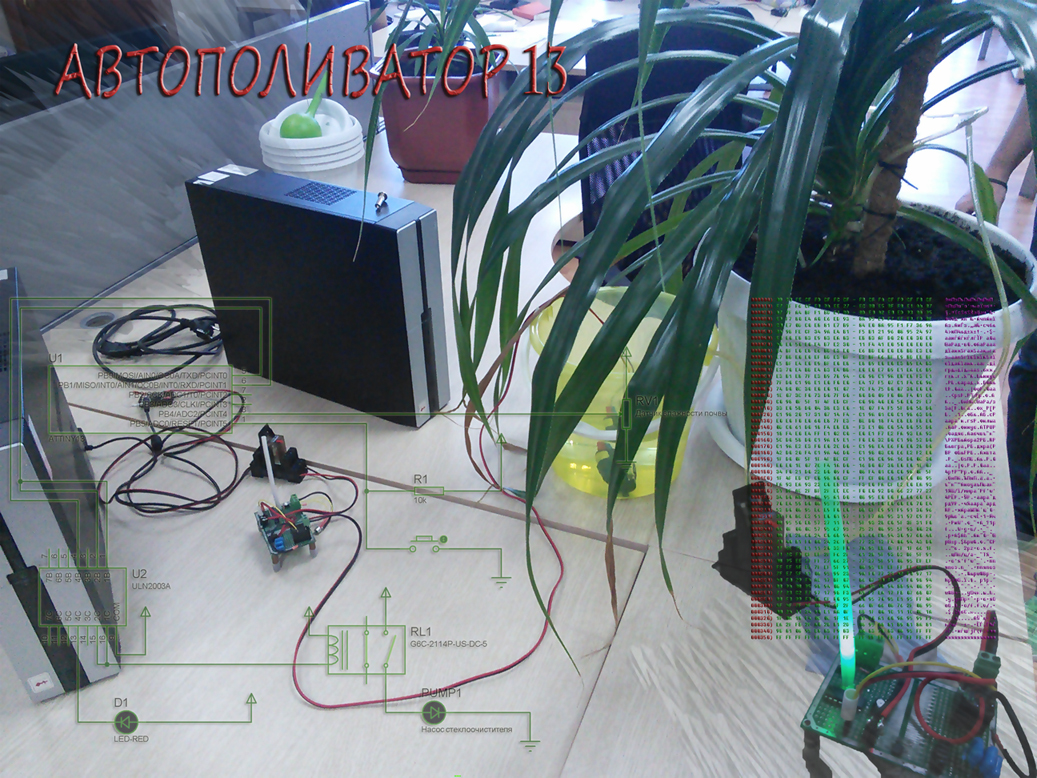
Then you can assemble the watering circuit, the capacitors are not indicated on the circuit, they are placed next to the consumers between the ground and the power:

Figure 11 (circuit in the proteus)
Well, something like this:
