Like we did a small security system on RPi. Part 1
Hello Hawkers!
I think many of you have heard about the Raspberry Pi, moreover, I think a fairly large number of you have seen it live. In early 2014, I decided that it was time for me to order a couple of RPi myself and do something interesting on them. Since I am an iOS developer, I got the idea to attach an iOS application to this project. Well, because RPi is pretty good at working with third-party hardware, I decided that I would make a small security system for personal use.
The first thing to do in this case was to determine what I want from this system. I believe that for such a task there is nothing better than a map of thoughts. In general, after 5 minutes of deep reflection, this is what happened:

About a month later, I received two RPi models A from the UK, i.e. with one USB, and without Ethernet. I bought a 16GB flash drive and installed Raspbian on it. And then the first of the pitfalls began to emerge - drivers and the Internet. I already had a 3G router that I won at a competition a couple of years ago, and I planned to connect it to RPi in order for the Internet to appear there. How wrong I was.
After half an hour, I was already in the store looking for a USB-Ethernet adapter, the seller hardly found me one copy of the D-Link company. Just before the exit, I decided to play it safe and buy a wifi adapter from ASUS, as well. the time was later, and I really wanted to start work today, so there was simply no right to make a mistake. On both devices, Linux support flaunted naturally.

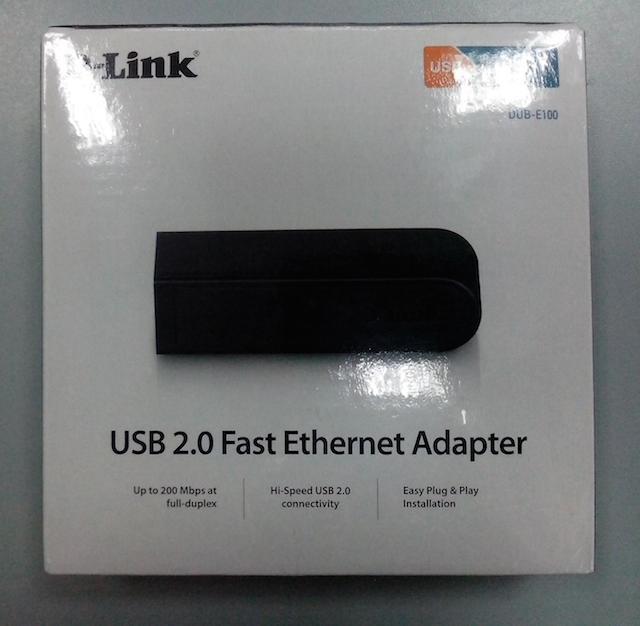
Arriving home, I killed a good hour in an attempt to install from the disk, and then find the latest drivers for D-Link on the Internet. It turned out that the guys from this company just stopped supporting this device 2 years ago! I realized that they sold me junk ( which I successfully exchanged the next day for two more flash drives) There was plan B, which worked surprisingly without any drivers, I just inserted the adapter from ASUS into USB and it was immediately identified in the system as a network card. I must say right away that it is simply impossible to work on the RPi model A in the graphic shell mode, everything is very slow, after the MacBook with SSD it's about hell. So I decided not to torment him, I just set up ssh for myself.
Then the question arose about the language in which I will write a system for working with hardware. Of all I chose Python, since there is work with hardware out of the box, there is no need to install any libraries or the like, well, plus, I have long wanted to learn this language.
In about a week, I mastered everything I needed from Python, it was a very interesting week. Remember in episode 9 of the first season of “The Big Bang Theories” the main characters attached switches to some devices in their apartment that could be controlled via the Internet, and anyone who wanted could turn on / off their lights or audio systems? I did the same with the LED connected to the RPi. This is certainly not an audio system, but when the LED lit up with a mouse click on the opposite hemisphere of the planet, the sensations were indescribable :)

The next question I had to solve was how to connect and control the iron, because the motion and smoke sensor is not an LED, everything is somewhat more complicated there. With this question, I turned to my good friend, who simply knows a lot about circuitry and is friends with a soldering iron better than me.
From that moment on, two people began to work on the project, and I became a frequent visitor to the amateur radio store.
I’ll tell you more about the operation of the circuit in another article, but for now I’ll briefly talk about how everything works.
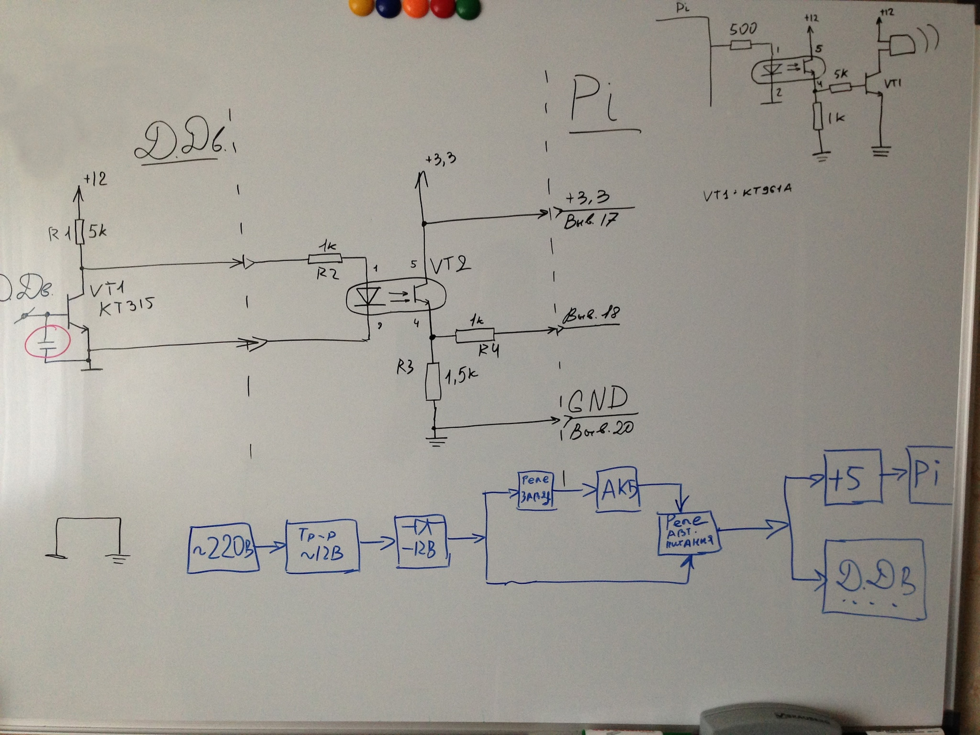
In this diagram, there is a motion sensor on the left, a car alarm on the right, and a connection to a power source below.
Looking ahead, I want to say that the automation of switching to battery power has been excluded from the circuit, because a battery was purchased that connects simply in parallel with mains power and automatically starts powering the circuit when 220V disappears. And it was decided to replace the limit switch for the door with reed switches.
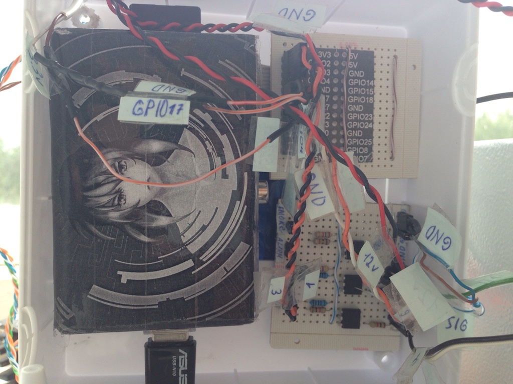
To connect and power the entire circuit, two separate boards were made, on one, work with iron was realized through optocouplers, and on the other, the conversion of the mains voltage of 220V to DC 12V and 5V. From 12V we have sensors and sirens, and from 5V respectively RPi.
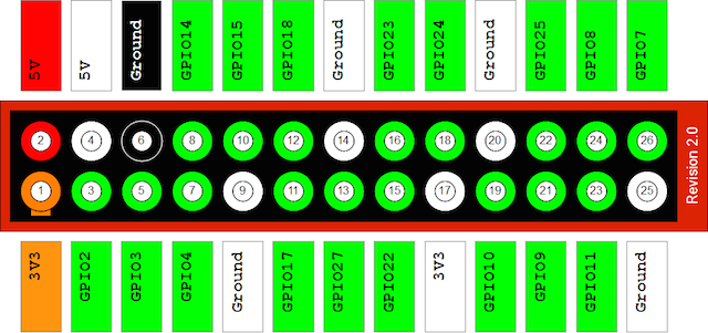
All this is good, but the next question was even more interesting, how do we get data from the sensors. We decided to do all the work with hardware via GPIO, to be honest, I think this is the only way, the rest of the inputs / outputs are for specific equipment, and we just need to get a status of 1 or 0 from the sensors. The
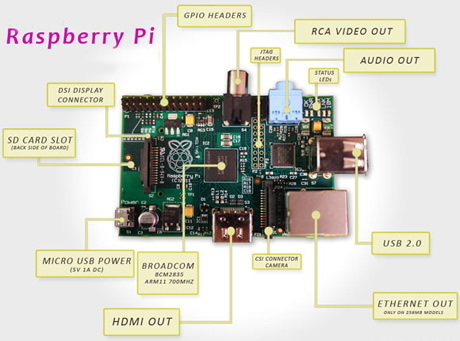
GPIO has 26 contacts, of which 2 are 5V, 2 to 3V, 5 ground, the rest can be either inputs or outputs, depending on the configuration you specify.
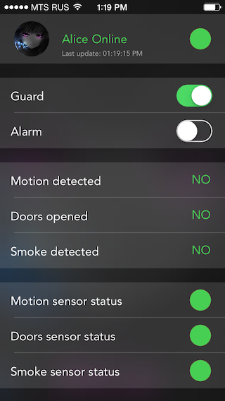
I decided to make a three-tier architecture: RPi - Web Server - iOS . Firstly, to increase fault tolerance, as if you exclude the server from the chain, the whole system becomes very vulnerable due to the fact that RPi can fail and we won’t know about it. Secondly, I decided to refuse to send SMS and dialers in favor of push notifications, which of course the server will send.
So, for programming the system of working with hardware, I chose Python 2.5. The first thing to do is install WebIOPi. This is an excellent open-source project that allows you to conveniently debug work with equipment through a browser. It shows the status of the GPIO ports, allows you to configure them for input / output and manually set it to output 0 or 1. It is installed very simply, on the Internet, there is even a detailed instruction in Russian.
As I wrote above, in Python out of the box there is work with GPIO, for this you just need to connect a special library.
GPIO has two contact numbering modes, by account on the board and by internal contact number. I recommend using account numbering, it's just easier.
Before starting the system, we need to initialize all the necessary ports, namely, specify how they will work, input or output, as well as indicate the initial value of the port.
To read the port, use the following code:
To install on the output of port 1 or 0:
Since the motion sensor gives a signal for a very short period of time, we need to read the ports constantly, and here it must be said that in RPi.GPIO this is implemented very conveniently. You can make sure that when you receive input 1 or 0, a certain function is called. Also, a read frequency is set for each port.
Some important pitfalls. You must make sleep (1) in the program loop, otherwise the processor will always be 100% loaded, and it is recommended that GPIO.cleanup () be executed when exiting the program.
Next, I’ll tell you about an even stranger problem, the reasons for which I did not find, but found a completely adequate solution. After about 6 hours of continuous operation, the script stops responding to the sensors. Most likely the very convenient system falls off, which calls callback functions when a certain event occurs. This is solved very simply, the script needs to be reloaded sometimes, for example using cron. For greater reliability, on my system, cron reloads the script every hour, plus every minute it checks whether the script is working and runs it if it is not.
I made the program work in the form of a demon, I think there is no need to explain anything here, this is a pretty standard thing. If desired, you can find examples on the Internet.
Let's talk a little about the system architecture. I put the work with each piece of iron into a separate module. Each module can initialize ports, turn on / off its hardware, conduct self-diagnostics, send messages to the server, for example, when a motion sensor is triggered, and of course, write its status in the log.
Self-diagnosis is done quite simply, during initialization, all the iron must have one at the output, so if we have zero there, then the sensor does not work or is not in the closed position (reed switch). Accordingly, the whole system is based on the fact that the sensors have 1 in a calm state, and accordingly 0 when they are triggered or something breaks.
In general, the system consists of 4 sensors: 360 ° motion sensor, smoke sensor, 2 reed switches. And of course, the siren, voiced, car, in a closed room just breaks his ears.
On this, the first part comes to an end, next time I will tell you how the server part and the iOS application were made. Thank you all for your attention, if possible I will answer all questions about hardware and software in the comments.
Well, in conclusion, a small spoiler for the second part :)
I think many of you have heard about the Raspberry Pi, moreover, I think a fairly large number of you have seen it live. In early 2014, I decided that it was time for me to order a couple of RPi myself and do something interesting on them. Since I am an iOS developer, I got the idea to attach an iOS application to this project. Well, because RPi is pretty good at working with third-party hardware, I decided that I would make a small security system for personal use.
Introduction
The first thing to do in this case was to determine what I want from this system. I believe that for such a task there is nothing better than a map of thoughts. In general, after 5 minutes of deep reflection, this is what happened:
About a month later, I received two RPi models A from the UK, i.e. with one USB, and without Ethernet. I bought a 16GB flash drive and installed Raspbian on it. And then the first of the pitfalls began to emerge - drivers and the Internet. I already had a 3G router that I won at a competition a couple of years ago, and I planned to connect it to RPi in order for the Internet to appear there. How wrong I was.
After half an hour, I was already in the store looking for a USB-Ethernet adapter, the seller hardly found me one copy of the D-Link company. Just before the exit, I decided to play it safe and buy a wifi adapter from ASUS, as well. the time was later, and I really wanted to start work today, so there was simply no right to make a mistake. On both devices, Linux support flaunted naturally.
Arriving home, I killed a good hour in an attempt to install from the disk, and then find the latest drivers for D-Link on the Internet. It turned out that the guys from this company just stopped supporting this device 2 years ago! I realized that they sold me junk ( which I successfully exchanged the next day for two more flash drives) There was plan B, which worked surprisingly without any drivers, I just inserted the adapter from ASUS into USB and it was immediately identified in the system as a network card. I must say right away that it is simply impossible to work on the RPi model A in the graphic shell mode, everything is very slow, after the MacBook with SSD it's about hell. So I decided not to torment him, I just set up ssh for myself.
Then the question arose about the language in which I will write a system for working with hardware. Of all I chose Python, since there is work with hardware out of the box, there is no need to install any libraries or the like, well, plus, I have long wanted to learn this language.
In about a week, I mastered everything I needed from Python, it was a very interesting week. Remember in episode 9 of the first season of “The Big Bang Theories” the main characters attached switches to some devices in their apartment that could be controlled via the Internet, and anyone who wanted could turn on / off their lights or audio systems? I did the same with the LED connected to the RPi. This is certainly not an audio system, but when the LED lit up with a mouse click on the opposite hemisphere of the planet, the sensations were indescribable :)
Work with iron
The next question I had to solve was how to connect and control the iron, because the motion and smoke sensor is not an LED, everything is somewhat more complicated there. With this question, I turned to my good friend, who simply knows a lot about circuitry and is friends with a soldering iron better than me.
From that moment on, two people began to work on the project, and I became a frequent visitor to the amateur radio store.
I’ll tell you more about the operation of the circuit in another article, but for now I’ll briefly talk about how everything works.
In this diagram, there is a motion sensor on the left, a car alarm on the right, and a connection to a power source below.
Looking ahead, I want to say that the automation of switching to battery power has been excluded from the circuit, because a battery was purchased that connects simply in parallel with mains power and automatically starts powering the circuit when 220V disappears. And it was decided to replace the limit switch for the door with reed switches.
To connect and power the entire circuit, two separate boards were made, on one, work with iron was realized through optocouplers, and on the other, the conversion of the mains voltage of 220V to DC 12V and 5V. From 12V we have sensors and sirens, and from 5V respectively RPi.
All this is good, but the next question was even more interesting, how do we get data from the sensors. We decided to do all the work with hardware via GPIO, to be honest, I think this is the only way, the rest of the inputs / outputs are for specific equipment, and we just need to get a status of 1 or 0 from the sensors. The
GPIO has 26 contacts, of which 2 are 5V, 2 to 3V, 5 ground, the rest can be either inputs or outputs, depending on the configuration you specify.
Programming a hardware system
I decided to make a three-tier architecture: RPi - Web Server - iOS . Firstly, to increase fault tolerance, as if you exclude the server from the chain, the whole system becomes very vulnerable due to the fact that RPi can fail and we won’t know about it. Secondly, I decided to refuse to send SMS and dialers in favor of push notifications, which of course the server will send.
So, for programming the system of working with hardware, I chose Python 2.5. The first thing to do is install WebIOPi. This is an excellent open-source project that allows you to conveniently debug work with equipment through a browser. It shows the status of the GPIO ports, allows you to configure them for input / output and manually set it to output 0 or 1. It is installed very simply, on the Internet, there is even a detailed instruction in Russian.
As I wrote above, in Python out of the box there is work with GPIO, for this you just need to connect a special library.
import RPi.GPIO as GPIOGPIO has two contact numbering modes, by account on the board and by internal contact number. I recommend using account numbering, it's just easier.
GPIO.setmode(GPIO.BOARD)Before starting the system, we need to initialize all the necessary ports, namely, specify how they will work, input or output, as well as indicate the initial value of the port.
GPIO.setup(12, GPIO.OUT, initial=GPIO.LOW)
GPIO.setup(11, GPIO.IN, pull_up_down=GPIO.PUD_DOWN)
To read the port, use the following code:
if (GPIO.input(11) == GPIO.HIGH)To install on the output of port 1 or 0:
GPIO.output(12, GPIO.HIGH)
GPIO.output(12, GPIO.LOW)
Since the motion sensor gives a signal for a very short period of time, we need to read the ports constantly, and here it must be said that in RPi.GPIO this is implemented very conveniently. You can make sure that when you receive input 1 or 0, a certain function is called. Also, a read frequency is set for each port.
GPIO.add_event_detect(11, GPIO.FALLING, callback=move_sensor_callback, bouncetime=500)
Some important pitfalls. You must make sleep (1) in the program loop, otherwise the processor will always be 100% loaded, and it is recommended that GPIO.cleanup () be executed when exiting the program.
try:
    while True:
        sleep(1)
finally:
	GPIO.cleanup()
Next, I’ll tell you about an even stranger problem, the reasons for which I did not find, but found a completely adequate solution. After about 6 hours of continuous operation, the script stops responding to the sensors. Most likely the very convenient system falls off, which calls callback functions when a certain event occurs. This is solved very simply, the script needs to be reloaded sometimes, for example using cron. For greater reliability, on my system, cron reloads the script every hour, plus every minute it checks whether the script is working and runs it if it is not.
I made the program work in the form of a demon, I think there is no need to explain anything here, this is a pretty standard thing. If desired, you can find examples on the Internet.
Let's talk a little about the system architecture. I put the work with each piece of iron into a separate module. Each module can initialize ports, turn on / off its hardware, conduct self-diagnostics, send messages to the server, for example, when a motion sensor is triggered, and of course, write its status in the log.
Self-diagnosis is done quite simply, during initialization, all the iron must have one at the output, so if we have zero there, then the sensor does not work or is not in the closed position (reed switch). Accordingly, the whole system is based on the fact that the sensors have 1 in a calm state, and accordingly 0 when they are triggered or something breaks.
In general, the system consists of 4 sensors: 360 ° motion sensor, smoke sensor, 2 reed switches. And of course, the siren, voiced, car, in a closed room just breaks his ears.
On this, the first part comes to an end, next time I will tell you how the server part and the iOS application were made. Thank you all for your attention, if possible I will answer all questions about hardware and software in the comments.
Well, in conclusion, a small spoiler for the second part :)