Making a small, self-powered monitor
In my spare time from IT, I am engaged in shooting video and designing radio-controlled machines.
In this article I will tell you how these interests intersected in the monitor.
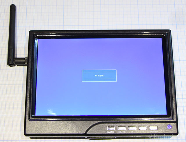
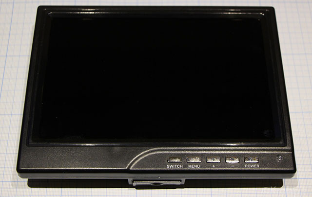
For greater convenience of monitoring video on a DSLR, a simple Chinese IPS monitor with a diagonal of 7 "bought the camera:

Main technical specifications:
Video inputs: HDMI, VGA, RCA;
Resolution: 1280x800;
Power supply: 5-30V DC (also works from a pair of computer USB outputs) ;
Power consumption: 6 W.
The monitor has good resolution for this size, IPS matrix with a large viewing angle and good color reproduction. The
monitor was powered from the outlet through an external adapter, but this is completely inconvenient for video recording.
First I found a ready-made solution - a VESA 75x75 compatible fastener for a standard battery from the camera is attached to the back of the monitor.

But this solution turned out to have many shortcomings: it is necessary to use an external charger, the battery capacity is enough for about 40 minutes, it is necessary to disconnect the battery, because in the “power off” mode, the monitor consumes a lot of energy, the battery module doubles the thickness of the monitor.
Although even in this version, I have a new direction of use.
Often in the data centers, rack sealing is used and it is difficult to connect the console to the front of the rack - there is no power for the monitor.
You have to connect the console from the back of the rack, making your way to the ports through cable organizers and then work in the hot corridor. Of course, things are not so bad with us and the vast majority of equipment uses ipKVM, but the situations are different, sometimes ipKVM itself requires configuration.
And then a solution appeared - from the front of the rack you hang the monitor by the hook (you can do it on a magnet, it doesn’t weigh much), you connect the VGA cable from the front of the server.
Then came another application.
I decided to put the FPV system on the RC car.
This monitor is connected to the receiver and secured to the radio remote control.
But in this decision, I did not like the bundle of wires connecting the monitor and the receiver, and the receiver also needed power.
In addition, the battery capacity of the camera was rather weak.
It was decided to do a deep tuning - put all the components inside the monitor case, getting rid of external wires as much as possible. Ideally, place the FPV receiver, battery and charger to it.
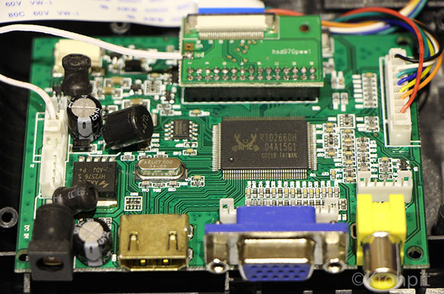
Dismantled the monitor - it turned out that half of the internal volume is free.

Disassembled and FPV receiver:
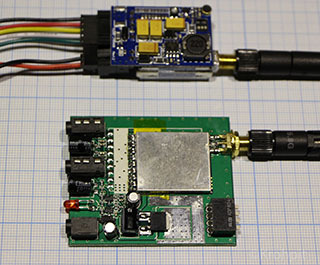
On top of the photo transmitter, bottom receiver.
The FPV receiver board consists of a standard receiver module (a small board in a metal screen) and a board on which the connectors and the power regulator are soldered.
The stabilizer turned out to be a linear type at 5V, i.e. all that is above the necessary goes into heat, high heating was associated with this. Current consumption about 200mA.
But the transmitter uses a more modern switching power supply stabilizer.
The standard receiving module can be powered in the range of 3.3-5V.
The receiving module is easily soldered. Carefully insert a thin knife or screwdriver between the main board and the receiving module, then unsolder the antenna and slightly raise the module with a knife. Next, gently lift the module by hand, and heat up the remaining leads with a soldering iron. I used a 100W soldering iron with a widely sharpened tip.

This module can be purchased separately, but I already had a ready-made kit.
In order not to reinvent the wheel to control the charge / discharge, the LiPo battery decided to use the standard Power Bank device for charging mobile devices.
I found on ebay suitable in size, capacity, return currents, equipped with a solar battery.
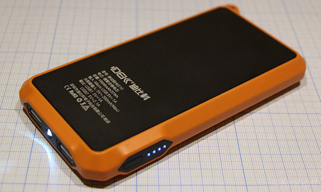
Why with a solar battery - as a rule, all Power Banks are recharged via a USB connector, and I would like to make a more universal solution. It will be possible to charge both from the USB connector and from the standard power connector on the monitor using an external power supply.
To begin with, I disassembled Power Bank, the insides fully met my expectations.
I must say that even though the device is Chinese, the case and the filling are made soundly.
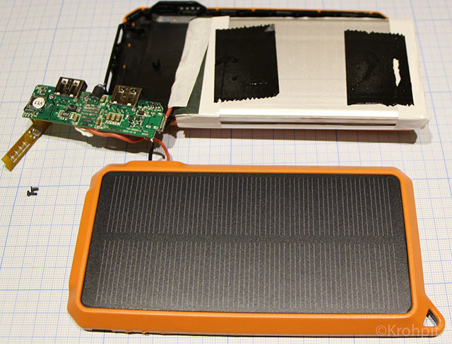
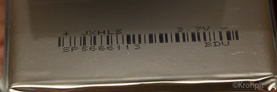
The LiPo battery consists of two flat rectangular cells. Only voltage is indicated in the marking. Elements are connected in parallel. The wires are connected through a small board with a protective controller.
Claimed battery capacity 10000mAh
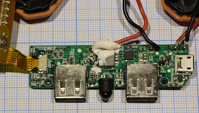
The board with a power controller and connectors is quite compact.

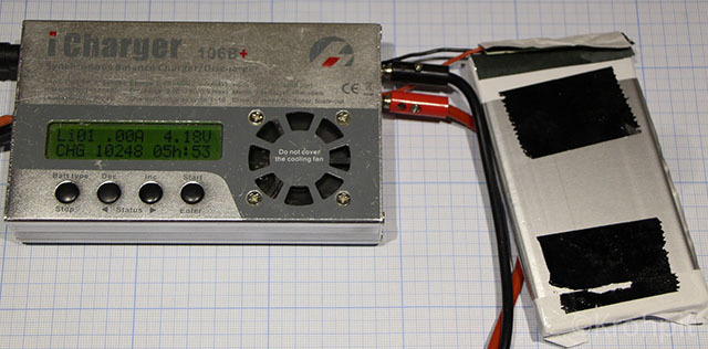
The first thing I decided to check the battery capacity, because in such devices, often declared characteristics are not true.
I soldered off the battery and connected it to an external charger.
Charged and discharged with a current of 2A, the capacity was slightly higher than the nominal.
I was pleasantly surprised that it corresponds to the declared capacity.
So, back to the monitor.
First, I had to take a Dremel hand milling cutter and a cutting wheel and saw off various plastic fasteners in the compartment where the receiver, the battery controller and the battery itself will be located.
Next was painstaking soldering.
On the monitor board, it is necessary to solder the input filter choke, the one immediately after the power connector, instead of it, solder the positive wire from the USB output connector to 2A of the battery controller. I soldered the wires at the places where the USB connectors were connected to the board.
The negative wire must be soldered to the common bus of the monitor controller. (for example, all the metal cases of the external connectors are soldered to minus)
To the second USB connector, which is 1A soldered to the positive input of the receiver.
The negative wire is also soldered to the common monitor bus.
Video output of the receiver to the central pin of the RCA connector.
A four-section switch of radio channels was dropped out of the receiver board, it was glued next to the antenna and connected with wires to the board.
To switch radio channels, you need three sections. They should be shorted to the common negative bus (for example, to the antenna connector housing).
I used the fourth section to turn on the radio receiver module. It consumes about 1W of energy, and this is a lot when powered by a battery.
Power Bank has its own power button, and at the same time an LED scale for the charge level.
The monitor itself turns on when the power is turned on, if it was de-energized when it was turned on (it remembers the previous state of its power button), so I unsoldered the two wires from the monitor’s power button and soldered this button parallel to the Power Bank button (it is located on a flexible cable with LEDs charge level).
I drilled small holes for the capacity indicator on the back cover and glued this cable with superglue. The battery controller board is glued with USB connectors to the back cover.
A mini-USB connector for charging comes out from the bottom of the monitor.


Everything is very tightly packed, there is no free space left.
There is a slight drawback - the battery significantly shifted the center of gravity.
The final mass is - 500g.
The battery life with the radio module on is 4.5 hours.
The monitor is quite warm during operation, at some points the temperature is about 55 degrees Celsius.
Thermal photos show the main places of heating: on top of the matrix (matrix controller), receiver module, battery controller, monitor power stabilizer.


That's all, thanks for your attention.
In this article I will tell you how these interests intersected in the monitor.
For greater convenience of monitoring video on a DSLR, a simple Chinese IPS monitor with a diagonal of 7 "bought the camera:
Main technical specifications:
Video inputs: HDMI, VGA, RCA;
Resolution: 1280x800;
Power supply: 5-30V DC (also works from a pair of computer USB outputs) ;
Power consumption: 6 W.
The monitor has good resolution for this size, IPS matrix with a large viewing angle and good color reproduction. The
monitor was powered from the outlet through an external adapter, but this is completely inconvenient for video recording.
First I found a ready-made solution - a VESA 75x75 compatible fastener for a standard battery from the camera is attached to the back of the monitor.
But this solution turned out to have many shortcomings: it is necessary to use an external charger, the battery capacity is enough for about 40 minutes, it is necessary to disconnect the battery, because in the “power off” mode, the monitor consumes a lot of energy, the battery module doubles the thickness of the monitor.
Although even in this version, I have a new direction of use.
Often in the data centers, rack sealing is used and it is difficult to connect the console to the front of the rack - there is no power for the monitor.
You have to connect the console from the back of the rack, making your way to the ports through cable organizers and then work in the hot corridor. Of course, things are not so bad with us and the vast majority of equipment uses ipKVM, but the situations are different, sometimes ipKVM itself requires configuration.
And then a solution appeared - from the front of the rack you hang the monitor by the hook (you can do it on a magnet, it doesn’t weigh much), you connect the VGA cable from the front of the server.
Then came another application.
I decided to put the FPV system on the RC car.
This monitor is connected to the receiver and secured to the radio remote control.
But in this decision, I did not like the bundle of wires connecting the monitor and the receiver, and the receiver also needed power.
In addition, the battery capacity of the camera was rather weak.
It was decided to do a deep tuning - put all the components inside the monitor case, getting rid of external wires as much as possible. Ideally, place the FPV receiver, battery and charger to it.
Dismantled the monitor - it turned out that half of the internal volume is free.
Disassembled and FPV receiver:
On top of the photo transmitter, bottom receiver.
The FPV receiver board consists of a standard receiver module (a small board in a metal screen) and a board on which the connectors and the power regulator are soldered.
The stabilizer turned out to be a linear type at 5V, i.e. all that is above the necessary goes into heat, high heating was associated with this. Current consumption about 200mA.
But the transmitter uses a more modern switching power supply stabilizer.
The standard receiving module can be powered in the range of 3.3-5V.
The receiving module is easily soldered. Carefully insert a thin knife or screwdriver between the main board and the receiving module, then unsolder the antenna and slightly raise the module with a knife. Next, gently lift the module by hand, and heat up the remaining leads with a soldering iron. I used a 100W soldering iron with a widely sharpened tip.
This module can be purchased separately, but I already had a ready-made kit.
In order not to reinvent the wheel to control the charge / discharge, the LiPo battery decided to use the standard Power Bank device for charging mobile devices.
I found on ebay suitable in size, capacity, return currents, equipped with a solar battery.
Why with a solar battery - as a rule, all Power Banks are recharged via a USB connector, and I would like to make a more universal solution. It will be possible to charge both from the USB connector and from the standard power connector on the monitor using an external power supply.
To begin with, I disassembled Power Bank, the insides fully met my expectations.
I must say that even though the device is Chinese, the case and the filling are made soundly.
The LiPo battery consists of two flat rectangular cells. Only voltage is indicated in the marking. Elements are connected in parallel. The wires are connected through a small board with a protective controller.
Claimed battery capacity 10000mAh
The board with a power controller and connectors is quite compact.
The first thing I decided to check the battery capacity, because in such devices, often declared characteristics are not true.
I soldered off the battery and connected it to an external charger.
Charged and discharged with a current of 2A, the capacity was slightly higher than the nominal.
I was pleasantly surprised that it corresponds to the declared capacity.
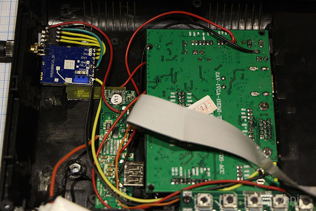
So, back to the monitor.
First, I had to take a Dremel hand milling cutter and a cutting wheel and saw off various plastic fasteners in the compartment where the receiver, the battery controller and the battery itself will be located.
Next was painstaking soldering.
On the monitor board, it is necessary to solder the input filter choke, the one immediately after the power connector, instead of it, solder the positive wire from the USB output connector to 2A of the battery controller. I soldered the wires at the places where the USB connectors were connected to the board.
The negative wire must be soldered to the common bus of the monitor controller. (for example, all the metal cases of the external connectors are soldered to minus)
To the second USB connector, which is 1A soldered to the positive input of the receiver.
The negative wire is also soldered to the common monitor bus.
Video output of the receiver to the central pin of the RCA connector.
A four-section switch of radio channels was dropped out of the receiver board, it was glued next to the antenna and connected with wires to the board.
To switch radio channels, you need three sections. They should be shorted to the common negative bus (for example, to the antenna connector housing).
I used the fourth section to turn on the radio receiver module. It consumes about 1W of energy, and this is a lot when powered by a battery.
Power Bank has its own power button, and at the same time an LED scale for the charge level.
The monitor itself turns on when the power is turned on, if it was de-energized when it was turned on (it remembers the previous state of its power button), so I unsoldered the two wires from the monitor’s power button and soldered this button parallel to the Power Bank button (it is located on a flexible cable with LEDs charge level).
I drilled small holes for the capacity indicator on the back cover and glued this cable with superglue. The battery controller board is glued with USB connectors to the back cover.
A mini-USB connector for charging comes out from the bottom of the monitor.
Everything is very tightly packed, there is no free space left.
There is a slight drawback - the battery significantly shifted the center of gravity.
The final mass is - 500g.
The battery life with the radio module on is 4.5 hours.
The monitor is quite warm during operation, at some points the temperature is about 55 degrees Celsius.
Thermal photos show the main places of heating: on top of the matrix (matrix controller), receiver module, battery controller, monitor power stabilizer.
That's all, thanks for your attention.