Configuring a Mikrotik router for various tasks in SOHO
- Tutorial
This article is a tracing-paper with my own internal instructions written by me, according to which we configure new routers in the company. Items will be arranged in a more or less chronological order, but each of them is an independent mini-instruction for one of the services used in our company.
The first thing to do is connect to the device. By default, the configuration on the router is configured for the subnet

We start
Double-click on the MAC address and connect with a name
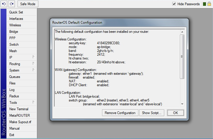
At the first login, the system will warn that an automatic router configuration script has been launched. We press the button
After that, we wait until the console
Having connected, we select on the left

We go in
We go in
For external interfaces, specify 11.11.11.11 with a distance of 4 and 22.22.22.22 with a distance of 3 as gateways.

After adding three routes (2 for external channels and 1 for the internal network), the router can be connected to the network and connected via IP 192.168.3.101 using the internal IP.
The configuration created above allows you to create 2 external interfaces, of which only one can work per unit of time - that is, the one with the distance shorter and the one with the largest one will work only when the cable is pulled from the first interface. For obvious reasons, this does not suit us - we need the simultaneous operation of two gateways. To do this, you need to teach the router to return traffic to the interface from which the request came. This is done by creating two additional routes and setting up a firewall. First, create the necessary routes. Previously created routes are also useful, but they can be cloned, because they will change slightly. To do this, click on the previously created route, press the button

go to
Create rules:
These steps must be repeated twice - for 2 external interfaces (brand
Next, you need to create 2 more rules that will direct outgoing traffic with notes
So, we have achieved the presence of two simultaneously working gateways, one of which has a higher priority than the second. The problem with this setting is that switching between gateways will be carried out exclusively when the physical link on the device interface falls. But there are other situations: the money on the account has run out, problems on the provider’s side, and so on — situations in which even the main gateway is accessible, but traffic does not go further than it and normally in this case the main gateway will not be switched. For auto-
We go in
Go to
Create a new rule:
To each of the hosts (8.8.8.8 and 8.8.4.4), we prescribe a unique route with a reduced distance through different gateways (11.11.11.11 and 22.22.22.22).
You
Go to
Create 2 rules for each of the external interfaces:
You can verify NAT by sending ping to one of the sites on the Internet from a computer connected to the internal interface of the router. If you disable one of the two NAT rules on the router, you can see how the trace changes to the selected host on the Internet.
In the company’s network, it was decided to use the 192.168.168.0/22 subnet, with client addresses starting with 192.168.170.2 and the gateway address (of the router itself) 192.168.170.1
Go to
We go to the menu item
Go to the tab
Go to the tab
For batch creation of secrets (accounts) VPN you can use a script.
You need to go into

After creating the script, just create a file in which to adhere to the following syntax:
Please note that the last line is empty. If it is not left empty, then the last filled line will not be processed.
Next you need to open the menu item
After these preparations, you can go into

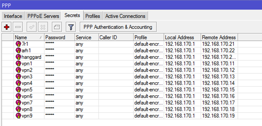
As a result of the script,
SSTP requires certificates to work . I used self-signed certificates issued by the OpenVPN snap-in . To obtain certificates, you do not need to install all the components,
Next, run cmd as administrator and go to the directory
Then, for convenience, I edited the file
After that, run in the following sequence:
For questions from the last command in, you can simply press enter (the
In the
Next,
Go to
Specify the profile name
Then,
Since when creating secrets (logins / passwords) for
Due to the fact that this article is about setting up a router, not a client, I will not consider ways to import this certificate into various OSs and setting up a client SSTP connection in this article. I only mention that the received certificate must be added to the trusted root certification authorities.
We go in
8.1. Access to the router
Create a rule:
Create 2 rules:
Go to
This rule is necessary to create access without using routing on the client machine, because 2.82 machine will have an additional
Go to
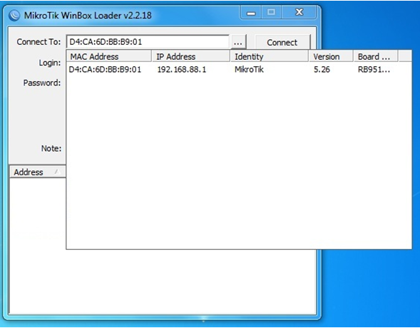
1. Power on, initial setup
The first thing to do is connect to the device. By default, the configuration on the router is configured for the subnet
192.168.88.0/24. Open in the browser address is downloaded and saved on the computer Winbox.exe. We start
Winbox, On the contrary, Connect topress the button "…", and after a few seconds your router should appear in the list. Double-click on the MAC address and connect with a name
adminwithout a password. At the first login, the system will warn that an automatic router configuration script has been launched. We press the button
Remove Configuration: After that, we wait until the console
Winboxcloses, and after a few seconds we start it again Winbox(from where you saved it) and again connect to the MAC address.Having connected, we select on the left
Interfacesand remove unnecessary interfaces - VLAN, Bridge. We go into the settings of each interface (there are only 5 of them on the company's router) and turn off Master-portand proxy-arp, leading the settings to the following form:2. Issue IP
We go in
IP — Addresses. We give the necessary interfaces the necessary addresses. In the case of using a router in the Escort network, 2 Internet providers and an internal network are connected to it. The second internal network is formed through a VPN. We indicate to each interface the necessary IP.[admin@Mikrotik] /ip address> print
Flags: X - disabled, I - invalid, D - dynamic
# ADDRESS NETWORK INTERFACE
0 I ;;; , !!!
10.0.33.1/24 10.0.33.0 ether4-hosting-network
1 22.22.22.17/29 22.22.22.16 ether2-gateway2
2 11.11.11.1/28 11.11.11.0 ether1-gateway1
3 192.168.3.101/22 192.168.0.0 ether3-internal-network
4 I 192.168.4.2/22 192.168.4.0 ether4-hosting-network
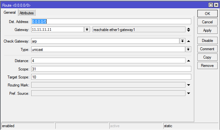
3. Routing
3.1. Create master and slave routes
We go in
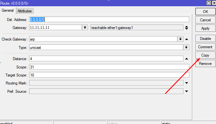
IP — Routes. By default, interfaces are used instead of hosts for routing. It is recommended to delete all static routes, and dynamic ones after changing the statics will change themselves. Attention: in order to delete everything painlessly, you need to connect to the router via a local network, without using routes, otherwise the connection will be disconnected when the main one is deleted . Next, create new routes: in the field, Dst.Addressspecify 0.0.0.0/0, in the Gateway field, specify the IP of the main gateway. Do not forget about the distance - on which route it is shorter, that will be the main one. In general, the route settings should look like this: For external interfaces, specify 11.11.11.11 with a distance of 4 and 22.22.22.22 with a distance of 3 as gateways.
After adding three routes (2 for external channels and 1 for the internal network), the router can be connected to the network and connected via IP 192.168.3.101 using the internal IP.
3.2. Create table routing
The configuration created above allows you to create 2 external interfaces, of which only one can work per unit of time - that is, the one with the distance shorter and the one with the largest one will work only when the cable is pulled from the first interface. For obvious reasons, this does not suit us - we need the simultaneous operation of two gateways. To do this, you need to teach the router to return traffic to the interface from which the request came. This is done by creating two additional routes and setting up a firewall. First, create the necessary routes. Previously created routes are also useful, but they can be cloned, because they will change slightly. To do this, click on the previously created route, press the button
Copyand addRouting Mark- mark the routes with the interface name, respectively. I called them to_ISP1and then to_ISP2go to
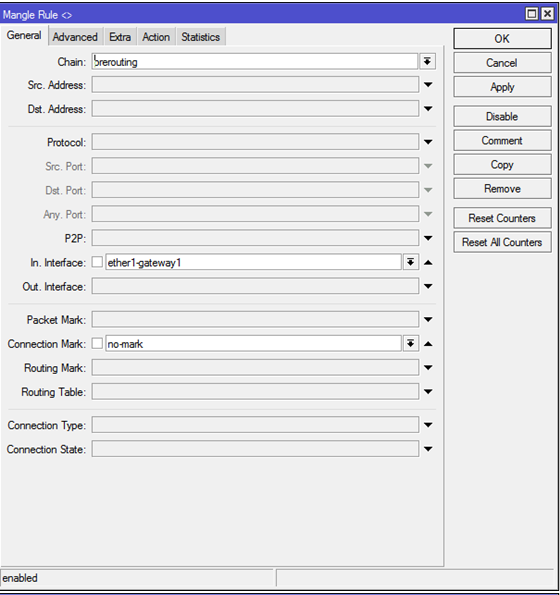
IP - Firewall - Mangle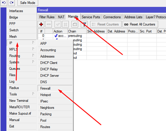
Create rules:
Вкладка General:
Chain: prerouting
In-interface: указываем один из входящих интерфейсов
Connection Mark: no-mark
Далее, на вкладке Action:
Action: mark connection
New Connection Mark: ISP1_conn
Passthrough: убираем галку.
Pictures for fastening material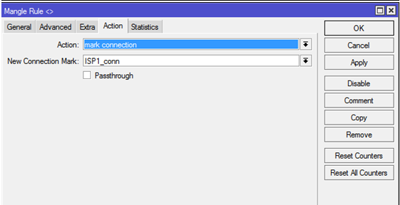
These steps must be repeated twice - for 2 external interfaces (brand
ISP1_connand, ISP2_connrespectively). Next, you need to create 2 more rules that will direct outgoing traffic with notes
ISP1_connand ISP2_connto the routes marked above. Create a rule:General:
Chain: output
Connection Mark: ISP1_conn
Action: mark routing
New Routing Mark: to_ISP1
Passthrough: убираем галку.
Images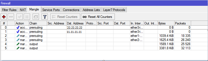

4. Route balancing in Master-Slave mode
So, we have achieved the presence of two simultaneously working gateways, one of which has a higher priority than the second. The problem with this setting is that switching between gateways will be carried out exclusively when the physical link on the device interface falls. But there are other situations: the money on the account has run out, problems on the provider’s side, and so on — situations in which even the main gateway is accessible, but traffic does not go further than it and normally in this case the main gateway will not be switched. For auto-
Netwatchswitching, you must use a function that monitors the presence of traffic on the interfaces and switches the traffic depending on the rules. Setting up this functionality consists of 3 stages.4.1. Create switch scripts
We go in
System — Scripts. We create 4 scripts with names ISP1-DOWN, ISP1-UP, ISP2-DOWN, ISP2-UP. All scripts are granted maximum rights.Script content
ISP1-DOWN:
ISP1-UP:
ISP2-DOWN:
ISP2-UP:
/ip route disable [find dst-address=0.0.0.0/0 and gateway=11.11.11.11 and distance >=4];
ISP1-UP:
/ip route enable [find dst-address=0.0.0.0/0 and gateway=11.11.11.11 and distance >= 4];
ISP2-DOWN:
/ip route disable [find dst-address=0.0.0.0/0 and gateway=22.22.22.22 and distance >=3];
ISP2-UP:
/ip route enable [find dst-address=0.0.0.0/0 and gateway=22.22.22.22 and distance >=3];
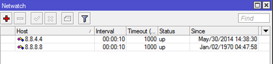
4.2. Create Netwatch Rules
Go to
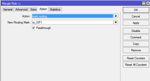
Tools — NetwatchCreate a new rule:
host: 8.8.4.4
Interval: 00:00:10
timeout: 1000ms
Up: ISP2-UP
Down: ISP2-DOWN
и второе правило:
host: 8.8.8.8
Interval: 00:00:10
timeout: 1000ms
Up: ISP1-UP
Down: ISP1-DOWN
Images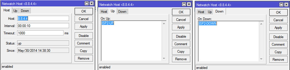
4.3. We create permanent independent routes
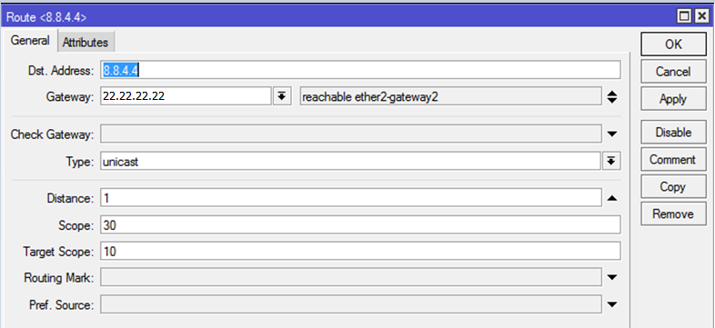
To each of the hosts (8.8.8.8 and 8.8.4.4), we prescribe a unique route with a reduced distance through different gateways (11.11.11.11 and 22.22.22.22).
You
netwatchcan check the operation by breaking the logical (not physical) link on one of the external interfaces. My company used a managed switch for this, which extinguished a port that was not adjacent to a router. Thus, ping to the host 8.8.8.8 was interrupted, but the physical link was active. After the ping stopped, Netwatch put out the necessary routes and the internal network got Internet access through the backup interface.5. Create NAT
Go to
IP — Firewall, go to the tab NATCreate 2 rules for each of the external interfaces:
Chain: srcnat
Out-Interface: указываем нужный внешний интерфейс
Action: masquerade
Picture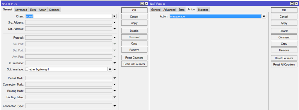
You can verify NAT by sending ping to one of the sites on the Internet from a computer connected to the internal interface of the router. If you disable one of the two NAT rules on the router, you can see how the trace changes to the selected host on the Internet.
6. Create a VPN server
6.1. We create the pool of IP addresses we need.
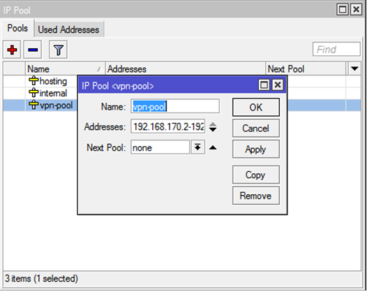
In the company’s network, it was decided to use the 192.168.168.0/22 subnet, with client addresses starting with 192.168.170.2 and the gateway address (of the router itself) 192.168.170.1
Go to
IP — Pooland create a new pool vpn-poolwith a range of 192.168.170.2-192.168.171.254:6.2. Turn on the PPTP server
We go to the menu item
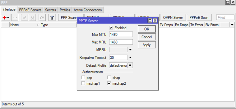
PPP, then on the tab Interfaceswe find the button PPTP Server. We put daws Enabled, mschap2and choose Default Profile: default-encoding.6.3. Configure Encryption
Go to the tab
PPP Profile. Tab Generalspecify Local Address: 192.168.170.1, Remote Address: vpn-pool. On the tab Protocolson the options Use Encryptionwe put the answer option Yes.6.4. Create Accounts
Go to the tab
Secrets. Create a user:Name: указываем логин
Password: Указываем пароль
Service: any
Profile: default-encryption
Local Address: 192.168.170.1
Remote Address: указываем, если необходимо, адрес из диапазона, созданного в vpn-pool. Если не указать адрес, то при подключении VPN будет выдаваться первый свободный.
Picture
6.5. Batch Account Creation
For batch creation of secrets (accounts) VPN you can use a script.
You need to go into
System — Scripts, click "create new" and paste the script text we need there.Script text
:global content [/file get [/file find name=vpnusers.txt] contents] ;
:global contentLen [ :len $content ] ;
:global lineEnd 0;
:global line "";
:global lastEnd 0;
:do {
       :set lineEnd [:find $content "\r\n" $lastEnd ] ;
       :set line [:pick $content $lastEnd $lineEnd] ;
       :set lastEnd ( $lineEnd + 2 ) ;
       :local tmpArray [:toarray $line] ;
	:if ( [:pick $tmpArray 0] != "" ) do={
	:put $tmpArray;
         /ppp secret add name=[:pick $tmpArray 0] password=[:pick $tmpArray 1] \
             local-address=[:pick $tmpArray 2] remote-address=[:pick $tmpArray 3] \
             profile=[:pick $tmpArray 4] service=[:pick $tmpArray 5];
}
} while ($lineEnd < $contentLen)
After creating the script, just create a file in which to adhere to the following syntax:
логин,пароль,IP_шлюза,IP_клиента,тип_шифрования,сервисThe finished file should look something like this
Please note that the last line is empty. If it is not left empty, then the last filled line will not be processed.
Next you need to open the menu item
Files. The created file must be dragged with the mouse into the resulting window. The file must be named vpnusers.txt, otherwise the script will not work. After these preparations, you can go into
System — Scripts, highlight with the mouse the script we need and click Run Script: As a result of the script,
PPP — Secretsyou can see the added accounts in7. Configure SSTP
SSTP requires certificates to work . I used self-signed certificates issued by the OpenVPN snap-in . To obtain certificates, you do not need to install all the components,
just the screenshots are enough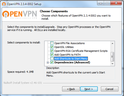
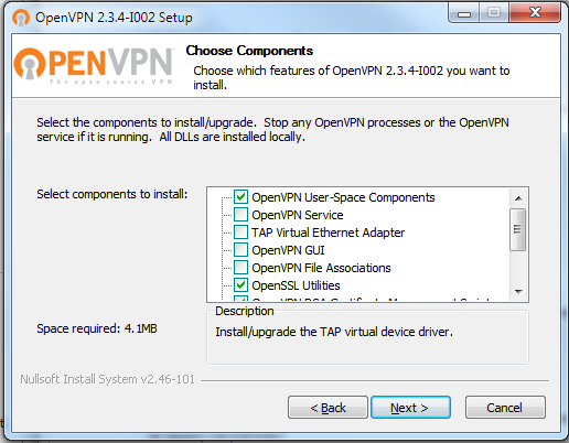
Next, run cmd as administrator and go to the directory
c:\Program Files\OpenVPN\easy-rsa\(or Program Files (x86)if you installed the 32-bit version of OpenVPN on 64-bit Windows). Open the file for editing vars.bat. If it is not, then rename it vars.bat.sampleto vars.batand bring it to the form:vars.bat
@echo off
rem Edit this variable to point to
rem the openssl.cnf file included
rem with easy-rsa.
set HOME=%ProgramFiles%\OpenVPN\easy-rsa
set KEY_CONFIG=openssl-1.0.0.cnf
rem Edit this variable to point to
rem your soon-to-be-created key
rem directory.
rem
rem WARNING: clean-all will do
rem a rm -rf on this directory
rem so make sure you define
rem it correctly!
set KEY_DIR=keys
rem Increase this to 2048 if you
rem are paranoid.  This will slow
rem down TLS negotiation performance
rem as well as the one-time DH parms
rem generation process.
set KEY_SIZE=1024
rem These are the default values for fields
rem which will be placed in the certificate.
rem Change these to reflect your site.
rem Don't leave any of these parms blank.
set KEY_COUNTRY=RU
set KEY_PROVINCE=Nsk
set KEY_CITY=Novosibirsk
set KEY_ORG=Escort
set KEY_EMAIL=i_nichupienko@soft-escort.ru
set KEY_CN=87.245.176.183
set KEY_NAME=temp_nie
set KEY_OU=changeme
set PKCS11_MODULE_PATH=changeme
set PKCS11_PIN=1234
Then, for convenience, I edited the file
build-ca.bat:build-ca.bat
@echo off
cd %HOME%
rem build a cert authority valid for ten years, starting now
"c:\Program Files\OpenVPN\bin\openssl.exe" req -days 3650 -nodes -new -x509 -keyout %KEY_DIR%\%1.key -out %KEY_DIR%\%1.crt -config %KEY_CONFIG%
After that, run in the following sequence:
c:\Program Files\OpenVPN\easy-rsa>vars.bat
c:\Program Files\OpenVPN\easy-rsa>clean-all.bat
c:\Program Files\OpenVPN\easy-rsa>build-ca.bat newuser
For questions from the last command in, you can simply press enter (the
vars.batdata entered in the file will be used ), or you can enter new data. In general, how convenient.Command execution
Result
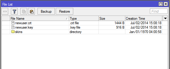
In the
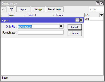
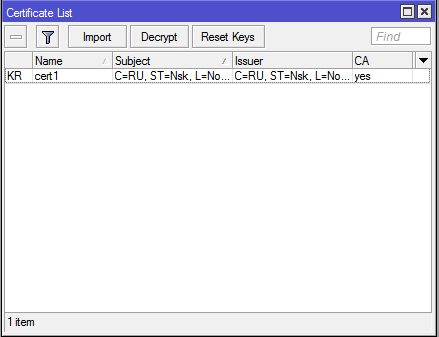
Winboxrouter, click the button Filesand copy the resulting files from the folder there using the Drag'n'Drop method. Next,
Winboxgo to System — Certificates. Click Import, select one file first, then the second: Go to
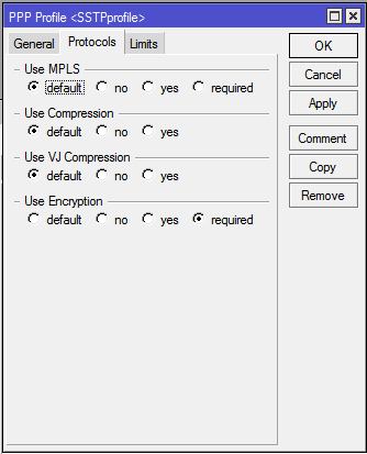
PPP — Profile, open the previously created one default-encryption, click Copyand on the tab Protocolchange the value of the field Use Encryptionfrom Yesto Required: Specify the profile name
SSTPprofile. Then,
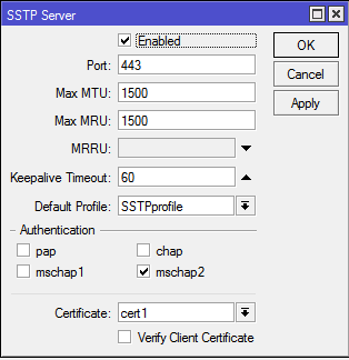
System — PPPgo to the tab Interfaceand click the button there SSTP-Server. We put a daw Enabled, select SSTPProfilein quality Default Profileand specify the certificate we need. As an authentication method, select only mschap2.Since when creating secrets (logins / passwords) for
PPPwe initially indicated the type of service Any, now we do not need to create anything additional. The connection is ready. Due to the fact that this article is about setting up a router, not a client, I will not consider ways to import this certificate into various OSs and setting up a client SSTP connection in this article. I only mention that the received certificate must be added to the trusted root certification authorities.
8. Configuring key firewall rules
We go in
IP — Firewall — Filter Rules8.1. Access to the router Winboxfrom the internal network
Create a rule:
Chain: Input
Protocol: tcp
Dst.Port: 8291
In. Interface: ether3-internal
Action: accept
Picture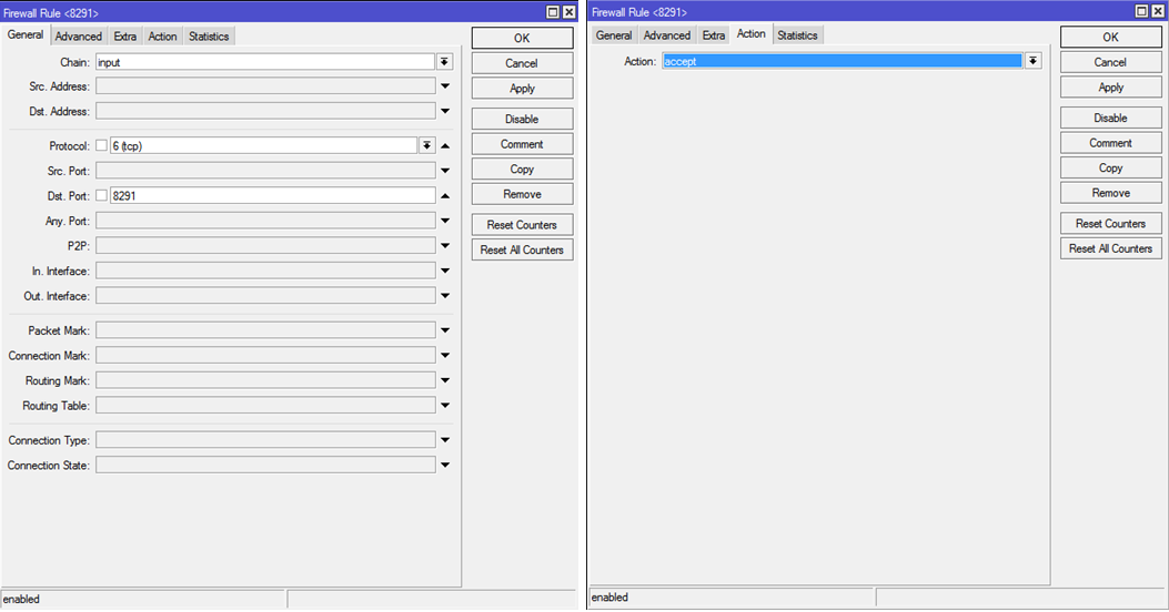
8.2. Ping out from the internal network
Create 2 rules:
Chain: forward
Protocol: icmp
Out. Interface: ether1-gateway1 и ether2-gateway2 (либо можно не указывать интерфейсы, т.к. вовнутрь пинг все равно будет закрыт натом. Тогда нужно одно правило, а не 2)
Action: accept
Picture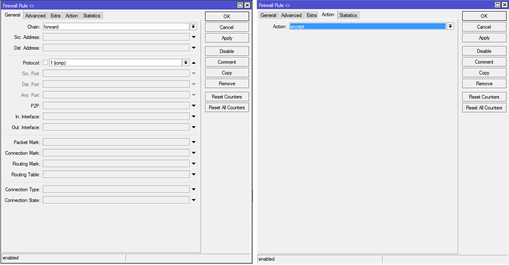
8.3. Ping an internal network from a VPN
Chain: forward
Protocol: icmp
Src.Address: 192.168.170.0/24
Dst.Address: 192.168.0.0/22
Action: accept
Picture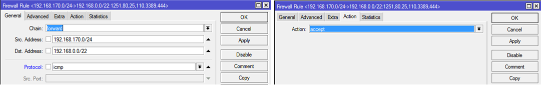
8.4. RDP access from VPN to internal network
Chain: forward
Protocol: tcp
Src.Address: 192.168.170.0/24
Dst.Address: 192.168.0.0/22
Dst.Port: 3389
Action: accept
Picture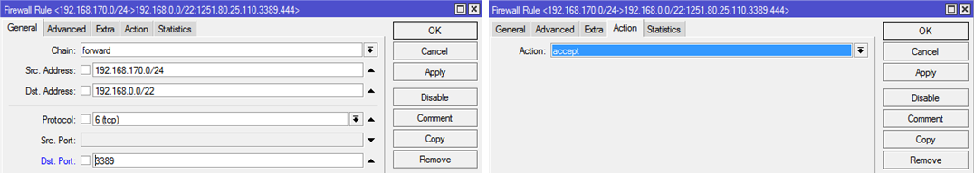
9. Publication of port 80 of machine 192.168.2.82 out
Go to
IP — Firewall — NATChain: dstnat
Protocol: tcp
Dst.Port: 80
In.Interface: ether1-gateway1 (для ether2-gateway2 надо создать точно такое же правило)
Action: netmap
To Addresses: 192.168.2.82
To Ports: 80
Picture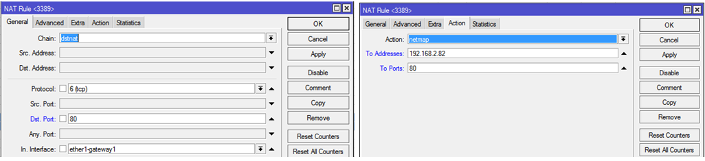
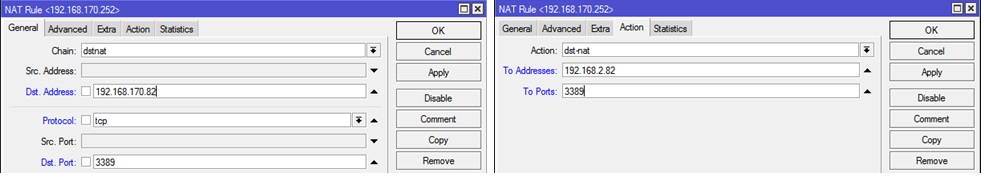
10. Publishing port 3389 of machine 192.168.2.82 to a VPN
This rule is necessary to create access without using routing on the client machine, because 2.82 machine will have an additional
IP-адрес:портfrom the same subnet segment as the VPN client. Go to
IP — Firewall — NATChain: dstnat
Dst.Address: 192.168.170.82
Protocol: tcp
Dst.Port: 3389
Action: dst-nat
To Addresses: 192.168.2.82
To Ports: 3389
Picture