Using the battery from the iPhone in the development of wearable electronics
Greetings reader.
Quite often, I have the task of developing portable devices powered by a single cell Li-ion battery. And, if the customer usually does not bother, then I, like an experienced engineer, at the sight of such TK, a shiver runs down my back. This is due to the fact that the assessment of the battery charge level, as well as the remaining operating time is a very difficult task, although at first glance it may seem different.
There are several options for action in this case, talk about them below.
- The simplest thing is not to do anything to determine the level of battery charge. The charge circuit on a simple linear memory (for example, TP4054) and a voltage converter to power the device. Turn off without warning and at the most inopportune moment.
- Measure the voltage on the battery. The result is about the same as the previous point, but it requires more effort. Typical circuit for measurement:
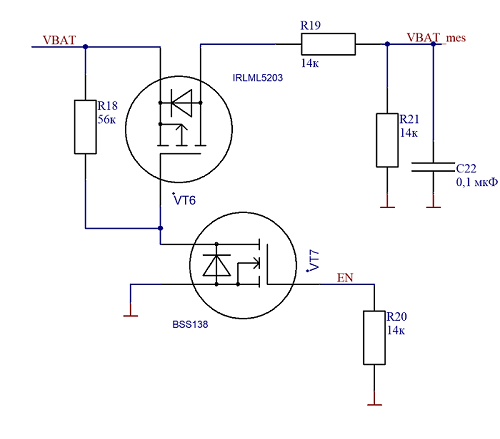
In fact, it is a voltage divider across resistors R19 and R21, connected via a VT6 switch. The VT7 transistor is needed to eliminate parasitic powering the MK through the EN output.
VBAT - battery voltage
VBAT_mes - voltage coming to the ADC
EN - divider control signal (0-off, 1-on)
Now we know the voltage of the battery, we are great fellows. BUT it gives almost nothing !!! The fact is that the typical Li-ion battery discharge curve, to put it mildly, is not linear and it depends on the current consumption and temperature of the battery itself:
Looking at these graphs, can you say what is the residual capacity of the battery at 3.5V? I think not ...
This method can be slightly improved by using the thermal sensor built into the MK to estimate the temperature of the battery, and either put a sensor to measure the current or (if the current consumption is approximately constant) build a discharge curve for a typical current consumption. This will allow at least a little justify the effort, but about any accuracy and can be no question. For charge indication on 3x LEDs - yes, it will.
In the case of a constant current consumption, you can consider the battery life and estimate the consumed charge and the time spent on charging to estimate the accumulated charge. This method gives a cumulative error, since calibration can only be at two points (full charge or full charge), but they are not always achieved. In addition, as the battery deteriorates, the maximum operating time should be adjusted, but in general, the method has the right to life.
- Make your own battery charge control system (BMS). For its implementation, we need sensors for current, temperature and battery voltage. We believe that the MK in the device already exists and it remains “only” to write software for it, which I spent a little less than a year.
-Take a ready-made Gas Gauge chip (for example, from TI or Maxim Integrated), configure it, calibrate it and work. For example, the scheme for bq27220:

There are several nuances when choosing this concept:
- To use more simple options for ready-made solutions such as CW2015:

This is the Chinese analogue of the MAX17048 chip. An absolutely simple microcircuit without temperature and current sensors, with corresponding low accuracy, but at the same time cheap, easy to use and program. It has the ability to work on the side of the device, which allows not to modify the battery itself. The chip was found on the network in the process of writing material, there is no experience with it, but there is a desire to try, because the option is really interesting. Perhaps in the next article I will talk about this chip in more detail.
-And finally, the last known method to which I want to devote today's article. In my opinion, this method is the easiest, but it gives the best result. It lies in the fact that we take the battery from the iPhone with built-in Gas Gauge and protection, we connect via HDQ or I2C, we poll and work. In this case, the battery is already assembled and calibrated. Below is a table with variants of the battery known to me: The

table is partially taken from ripitapart.com and www.macplus.ru . Please pay special attention to an unknown controller labeled A1141. This chip is manufactured by PowerFlash and this is all the information that was found. Blog author, from which I took the table, was not sure that he got the original battery from the iPhone SE. Thanks to the recall of asterix_tyumen , which dismantled the original battery from the SE, it was found that it costs sn27545. Below, we will be forced to consider A1141 in more detail. But for now look at the batteries:
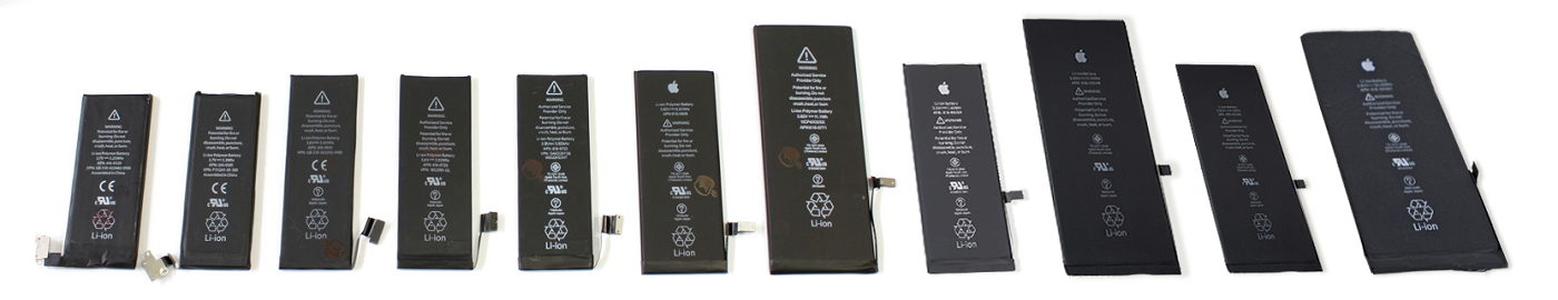
As you can see, the battery for every taste and color, with and without an apple. They can also be connected in parallel to increase capacity, with separate polling. Among the drawbacks, it is worth noting that the length / width ratio is approximately 3: 1, which is not always convenient, as well as a unique connector for connection. Due to the popularity of Apple phones, these batteries can be easily bought in many places and in large quantities (as it turned out, this is not quite true).
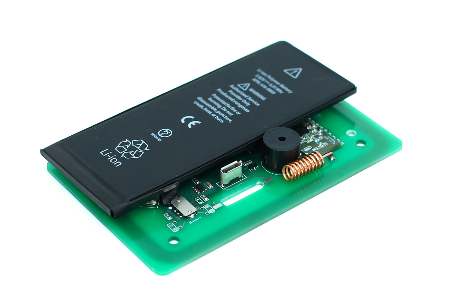
When developingWireless autonomous RFID reader, we went this way.
The battery was chosen from the iPhone 6, which suited us in terms of capacity and size. Several copies were purchased in different places for verification: the

Right was purchased in China, the rest in Moscow. Cost $ 6-11. When they are checked, quite interesting results will be obtained. Pay special attention to the box with the inscription "Orig", later we will return to it. The test was carried out using the RFID reader itself, the T23 EV2300 programmer and the Battery Management Studio program.
The power supply circuit of the RFID reader is shown in the figure:

Linear charger based on STC4054 (TP4054), charge current 500 mA, power switch with automatic pickup based on SF6 reed switch, capacitor C19, diode VD4 and resistor R15, as well as a pulse converter based on NCP1529.
First, I connected a copy from China for $ 6: The
battery responds, BUT the current was not displayed either when charged or discharged, the voltage did not match the actually measured and the degree of charge did not change. I did not answer the battery commands. There was an assumption that this copy was a fake, so I removed the protective tape from it to look at the board:

This is a turn ... I didn’t even redraw the circuit - it’s clear that the bq27545 emulator and overdischarge / overload protection circuit is worth it. Immediately there was an idea to save yourself time and open all the batteries.

The neighbor to the left of the Chinese colleague for $ 8 is similar with the difference in marking on the chips. The rest behaves the same. These 2 copies immediately in the trash. Unfortunately, I did not have an iPhone 6 on hand to check these batteries in the target device, it was very interesting to see how the phone would have behaved when working on these batteries.

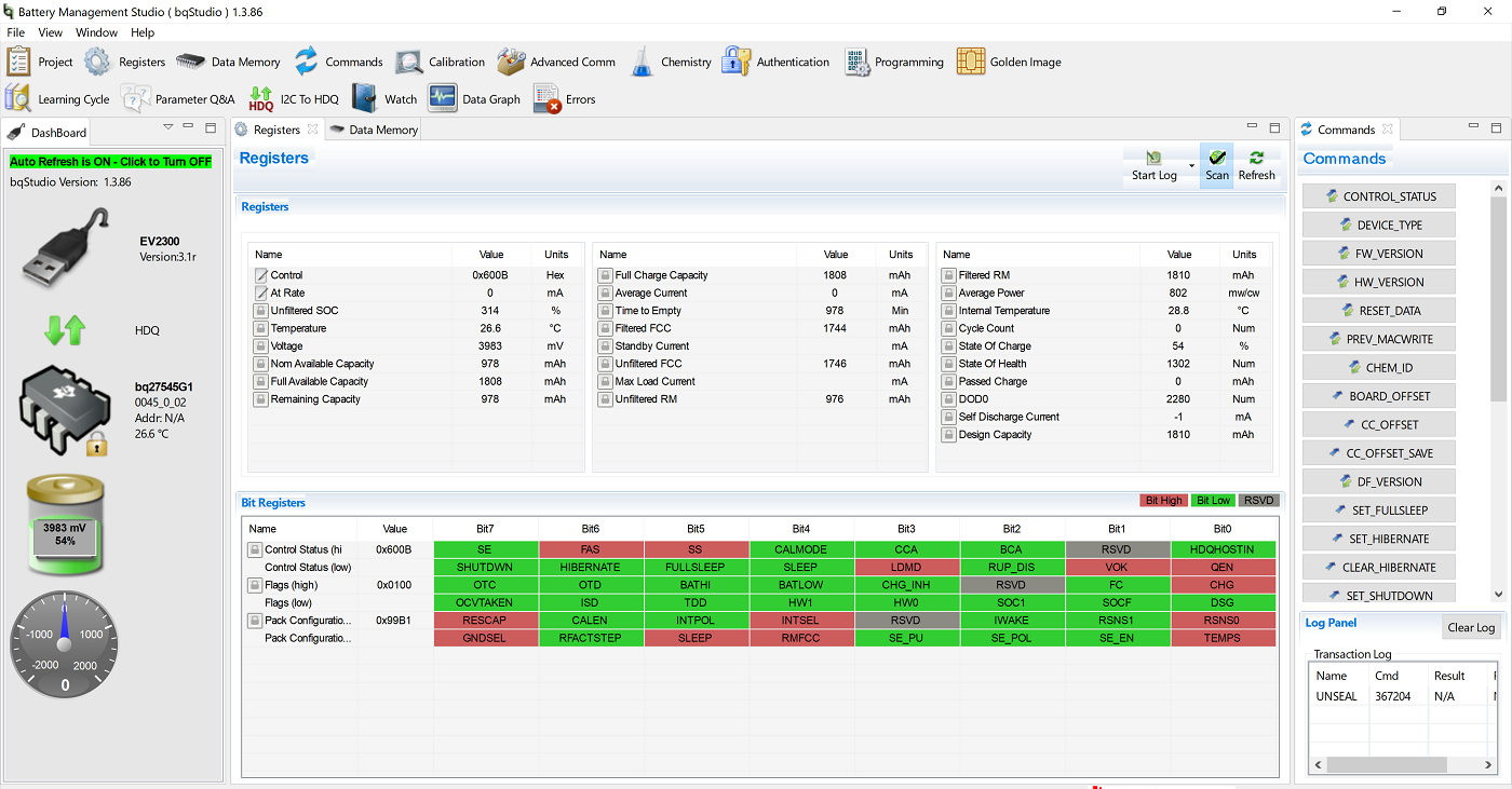
And this is a central battery, worth $ 8. It even has a current sensor and some kind of 8 pin chip with a modest 6G3 marking. In Battery Management Studio, this battery pretends to be more sophisticated bq27545. Displays charge level, correct voltage, battery current. But if all this was real, then a fake would not be a fake. In reality, the temperature was set by a constant, the current was measured very badly. The picture shows the current consumption of the RFID reader, which is measured by the battery while constantly reading the card.
In reality, it is ~ 55 mA for this mode of operation and, since the reader field is always on, it cannot be zero. When charging (when the current is constant for a long period of time), the current sensor works normally. Naturally, all other parameters are calculated incorrectly (charge level, operation time until full discharge, etc.). Flag FC (Full charge) is set at a voltage of 4.4V.

The battery is not responding to commands, the QEN and RUP_DIS flags are not set. In general, this is an unsuccessful attempt by the Chinese to write the bq27545 snag on MK (in any case, I think this is so). Also in the trash.
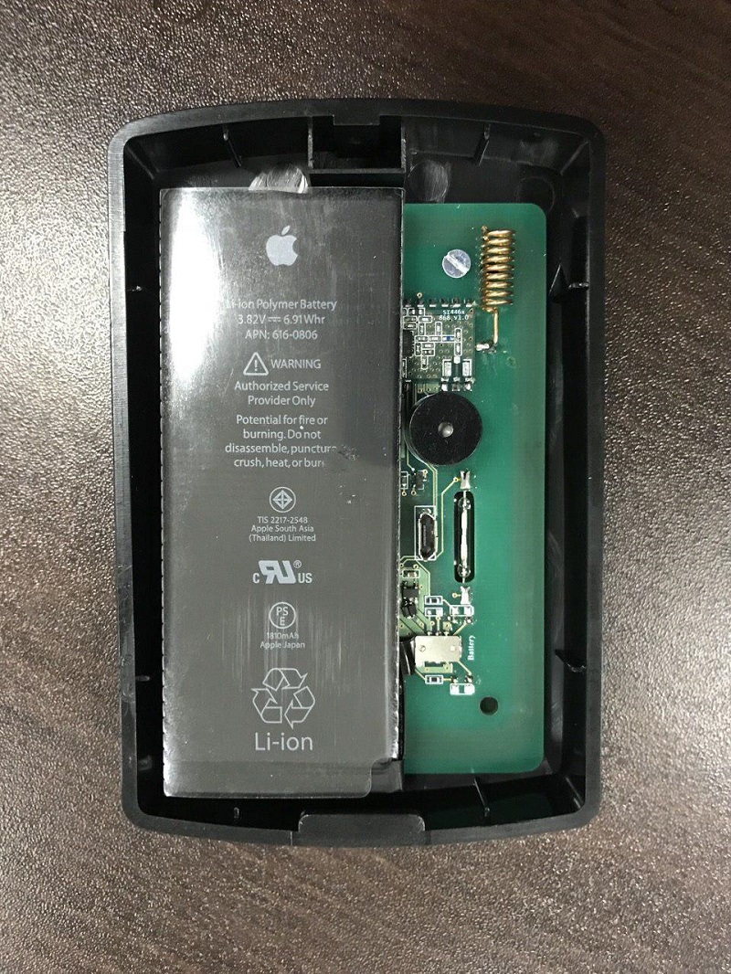
Remember, I asked to pay special attention to the copy in a box with the inscription "Orig"? It was he who turned out to be as close as possible to what we were looking for (and how can we disbelieve advertising now?):

Its cost was $ 9. In the center, the chip with the marking SN27545 is perfectly visible - this is exactly what we were looking for. With this instance, I began to work more closely. During the charge-discharge trial cycle, problems arose. I could not get the FC flag set (Full charge), which meant the end of the charge process. The charge current at a battery voltage close to 4.2V became extremely small (about 20mA) and the charging process threatened to never end. One of the possible reasons was a USB cable with a large voltage drop (it reached 4.5V before the memory chip), we replaced it with a better one with a lower voltage drop. The indicators improved, the battery charged up to 4.2V, the current dropped to 0, but SOC (State of charge) reached only 85, respectively, the FC flag was not set.

For several days I drove cycles with the expectation that the battery would learn, but this did not help. The problem turned out to be banal, but its search took 2 days. At some point, I noticed that the battery is 4.35V and this was the answer to all the questions. The memory is standard at 4.2V and I did not notice at all that the battery is 4.35V and there is an incomplete charge. Since the boards were already made, the only option to get out of the situation was to search for a replacement for the STC4054 with a voltage of 4.35V. It turned out that such microcircuits exist, but in our great country they cannot be easily bought (apparently unpopular from the word at all). Therefore, the MCP73832T-3 version was ordered with a wait of a couple of weeks.
In the meantime, the ordered rides, we will make a collective farm patch to check the concept. To do this, we make a “backup” of 0.15V for the memory chip using a diode:

It must be admitted that the collective farm has earned, the FC flag has been established, everything works, but the final voltage of the battery is 4.4 V (the drop on the diode is greater than the required 0.15 V).

It is important to note that it is possible to charge up to 4.2 V with a corresponding loss of ~ 15% of capacity, but at the same time significantly extend the life of the battery. With the copy of "Orig" we finished - it can be safely laid in the development.
Left the last copy. The most expensive ($ 11), in the coolest package and demanded the most time for yourself. Look inside:

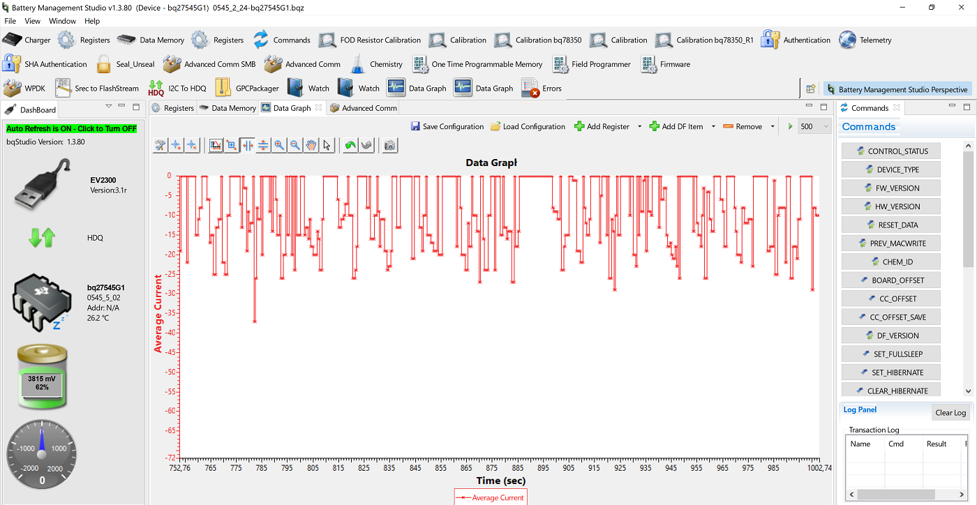
Here it is an unknown A1141 chip on which there is no documentation other than the manufacturer's page . When forcibly connected to bq27545 in Battery Management Studio, we see the following picture:

Complete trash. When trying to charge with a current of ~ 500 mA, it shows 125 mA, when discharging with a current of ~ 25 mA, it shows 214 mA. It is clear that if the A1141 has other parameter addresses or a data storage format different from bq27545, then nothing shines without documentation from this battery. Therefore, it was put aside, but at the end of the writing of the material, I decided to connect it again. I took the command table of the bq27545 chip:

And counted the voltage registers (0x08 and 0x09) through the Advanced Comm menu:

We get 0x10 << 8 | 0x38 = 4152 or 4.152V, which corresponds to a voltage of 4.15V measured by a multimeter. So if the data is correct, why does the program display 57mV ??? We notice that 57mV is exactly 0x38, that is, the value of the 0x08 register. With a battery voltage of 4.152 V, the charge level of 96% looks quite correct, it can be obtained by considering the registers 0x2c and 0x2d. Read 0x2c = 0x60, 0x2d = 0 (in the case of the SOC parameter, the upper register is always zero). It has been suggested that the program or the EV2300 cannot count (or the battery does not respond) either the high byte in the request or the byte with an odd address. To test this theory, the battery was connected directly to the RFID reader and the battery was polled through the MC. HDQ interface was implemented according to the TI document.. The bq27545 microcircuit uses the single-wire HDQ protocol for communication with the controlling controller, which is quite conveniently implemented on the STM32 based on the single-wire UART thanks to the support of the Half Duplex mode.
Because Our RFID reader works on MicroPython, we wrapped the work with HDQ into a class and got a work with a charge controller in the following form:
from hdq import HDQ
bat = HDQ (pyb.UART (1))
bat.charge () # charge
bat.read_u16 ( 0x14) # arbitrary register
In fact, it turned out that A1141 does not respond to a request to read bytes with odd addresses.

The oscillogram shows that there is a request, but there is no answer. When they added the reboot of the logic of data exchange (Break) before each request - once, but the chip began to respond correctly.

Then they compared the exchange speed of the EV2300 and the RFID reader and it turned out that the EV2300 uses a speed lower by 10-15% than the TI sets:

After reducing the HDQ speed and performing Break, each time the battery worked, it worked fine! The main battery parameters were read:

Complete victory! In fact, the A1141 turned out to be a high-quality clone bq27545 with a few drawbacks. It remains to talk about the nuances of working with the battery by the software (using sleep modes, wake-up current, etc.), but this will double the recording volume and, perhaps, I will write it another time.
As you can see, there are many options for the development of devices powered by Li-ion batteries. Honestly, it was originally planned to write material in the style came, saw, won, but in the process many nuances came out (the fight against A1141 is especially good) and the material was very interesting and extensive. From 5 copies of batteries, only 2 in fact can be used normally. Therefore, the choice of supplier in this case is very relevant. If you have seen batteries from other devices that contain BMS, then write the models in the comments. Thank you all for your attention!
Quite often, I have the task of developing portable devices powered by a single cell Li-ion battery. And, if the customer usually does not bother, then I, like an experienced engineer, at the sight of such TK, a shiver runs down my back. This is due to the fact that the assessment of the battery charge level, as well as the remaining operating time is a very difficult task, although at first glance it may seem different.
There are several options for action in this case, talk about them below.
- The simplest thing is not to do anything to determine the level of battery charge. The charge circuit on a simple linear memory (for example, TP4054) and a voltage converter to power the device. Turn off without warning and at the most inopportune moment.
- Measure the voltage on the battery. The result is about the same as the previous point, but it requires more effort. Typical circuit for measurement:
In fact, it is a voltage divider across resistors R19 and R21, connected via a VT6 switch. The VT7 transistor is needed to eliminate parasitic powering the MK through the EN output.
VBAT - battery voltage
VBAT_mes - voltage coming to the ADC
EN - divider control signal (0-off, 1-on)
Now we know the voltage of the battery, we are great fellows. BUT it gives almost nothing !!! The fact is that the typical Li-ion battery discharge curve, to put it mildly, is not linear and it depends on the current consumption and temperature of the battery itself:
Looking at these graphs, can you say what is the residual capacity of the battery at 3.5V? I think not ...
This method can be slightly improved by using the thermal sensor built into the MK to estimate the temperature of the battery, and either put a sensor to measure the current or (if the current consumption is approximately constant) build a discharge curve for a typical current consumption. This will allow at least a little justify the effort, but about any accuracy and can be no question. For charge indication on 3x LEDs - yes, it will.
In the case of a constant current consumption, you can consider the battery life and estimate the consumed charge and the time spent on charging to estimate the accumulated charge. This method gives a cumulative error, since calibration can only be at two points (full charge or full charge), but they are not always achieved. In addition, as the battery deteriorates, the maximum operating time should be adjusted, but in general, the method has the right to life.
- Make your own battery charge control system (BMS). For its implementation, we need sensors for current, temperature and battery voltage. We believe that the MK in the device already exists and it remains “only” to write software for it, which I spent a little less than a year.
-Take a ready-made Gas Gauge chip (for example, from TI or Maxim Integrated), configure it, calibrate it and work. For example, the scheme for bq27220:
There are several nuances when choosing this concept:
- In case the battery is removable, it is necessary either to install a charge determination circuit on the battery itself (otherwise it will be reset when disconnected), or to use special versions of Gas Gauge that allow the battery to be disconnected. In the first case, the battery of your device becomes unique and its replacement is possible only with your participation, which is not always convenient. In the second case, there is the problem of placing the temperature sensor on the battery.
- High cost solution. Main components: Gas Gauge microcircuit, protection microcircuit, transistors, thermistor, current sensor resistor.
- To use more simple options for ready-made solutions such as CW2015:
This is the Chinese analogue of the MAX17048 chip. An absolutely simple microcircuit without temperature and current sensors, with corresponding low accuracy, but at the same time cheap, easy to use and program. It has the ability to work on the side of the device, which allows not to modify the battery itself. The chip was found on the network in the process of writing material, there is no experience with it, but there is a desire to try, because the option is really interesting. Perhaps in the next article I will talk about this chip in more detail.
-And finally, the last known method to which I want to devote today's article. In my opinion, this method is the easiest, but it gives the best result. It lies in the fact that we take the battery from the iPhone with built-in Gas Gauge and protection, we connect via HDQ or I2C, we poll and work. In this case, the battery is already assembled and calibrated. Below is a table with variants of the battery known to me: The
table is partially taken from ripitapart.com and www.macplus.ru . Please pay special attention to an unknown controller labeled A1141. This chip is manufactured by PowerFlash and this is all the information that was found. Blog author, from which I took the table, was not sure that he got the original battery from the iPhone SE. Thanks to the recall of asterix_tyumen , which dismantled the original battery from the SE, it was found that it costs sn27545. Below, we will be forced to consider A1141 in more detail. But for now look at the batteries:
As you can see, the battery for every taste and color, with and without an apple. They can also be connected in parallel to increase capacity, with separate polling. Among the drawbacks, it is worth noting that the length / width ratio is approximately 3: 1, which is not always convenient, as well as a unique connector for connection. Due to the popularity of Apple phones, these batteries can be easily bought in many places and in large quantities (as it turned out, this is not quite true).
When developingWireless autonomous RFID reader, we went this way.
The battery was chosen from the iPhone 6, which suited us in terms of capacity and size. Several copies were purchased in different places for verification: the
Right was purchased in China, the rest in Moscow. Cost $ 6-11. When they are checked, quite interesting results will be obtained. Pay special attention to the box with the inscription "Orig", later we will return to it. The test was carried out using the RFID reader itself, the T23 EV2300 programmer and the Battery Management Studio program.
The power supply circuit of the RFID reader is shown in the figure:
Linear charger based on STC4054 (TP4054), charge current 500 mA, power switch with automatic pickup based on SF6 reed switch, capacitor C19, diode VD4 and resistor R15, as well as a pulse converter based on NCP1529.
First, I connected a copy from China for $ 6: The
battery responds, BUT the current was not displayed either when charged or discharged, the voltage did not match the actually measured and the degree of charge did not change. I did not answer the battery commands. There was an assumption that this copy was a fake, so I removed the protective tape from it to look at the board:
This is a turn ... I didn’t even redraw the circuit - it’s clear that the bq27545 emulator and overdischarge / overload protection circuit is worth it. Immediately there was an idea to save yourself time and open all the batteries.
The neighbor to the left of the Chinese colleague for $ 8 is similar with the difference in marking on the chips. The rest behaves the same. These 2 copies immediately in the trash. Unfortunately, I did not have an iPhone 6 on hand to check these batteries in the target device, it was very interesting to see how the phone would have behaved when working on these batteries.
And this is a central battery, worth $ 8. It even has a current sensor and some kind of 8 pin chip with a modest 6G3 marking. In Battery Management Studio, this battery pretends to be more sophisticated bq27545. Displays charge level, correct voltage, battery current. But if all this was real, then a fake would not be a fake. In reality, the temperature was set by a constant, the current was measured very badly. The picture shows the current consumption of the RFID reader, which is measured by the battery while constantly reading the card.
In reality, it is ~ 55 mA for this mode of operation and, since the reader field is always on, it cannot be zero. When charging (when the current is constant for a long period of time), the current sensor works normally. Naturally, all other parameters are calculated incorrectly (charge level, operation time until full discharge, etc.). Flag FC (Full charge) is set at a voltage of 4.4V.
The battery is not responding to commands, the QEN and RUP_DIS flags are not set. In general, this is an unsuccessful attempt by the Chinese to write the bq27545 snag on MK (in any case, I think this is so). Also in the trash.
Remember, I asked to pay special attention to the copy in a box with the inscription "Orig"? It was he who turned out to be as close as possible to what we were looking for (and how can we disbelieve advertising now?):
Its cost was $ 9. In the center, the chip with the marking SN27545 is perfectly visible - this is exactly what we were looking for. With this instance, I began to work more closely. During the charge-discharge trial cycle, problems arose. I could not get the FC flag set (Full charge), which meant the end of the charge process. The charge current at a battery voltage close to 4.2V became extremely small (about 20mA) and the charging process threatened to never end. One of the possible reasons was a USB cable with a large voltage drop (it reached 4.5V before the memory chip), we replaced it with a better one with a lower voltage drop. The indicators improved, the battery charged up to 4.2V, the current dropped to 0, but SOC (State of charge) reached only 85, respectively, the FC flag was not set.
For several days I drove cycles with the expectation that the battery would learn, but this did not help. The problem turned out to be banal, but its search took 2 days. At some point, I noticed that the battery is 4.35V and this was the answer to all the questions. The memory is standard at 4.2V and I did not notice at all that the battery is 4.35V and there is an incomplete charge. Since the boards were already made, the only option to get out of the situation was to search for a replacement for the STC4054 with a voltage of 4.35V. It turned out that such microcircuits exist, but in our great country they cannot be easily bought (apparently unpopular from the word at all). Therefore, the MCP73832T-3 version was ordered with a wait of a couple of weeks.
In the meantime, the ordered rides, we will make a collective farm patch to check the concept. To do this, we make a “backup” of 0.15V for the memory chip using a diode:
It must be admitted that the collective farm has earned, the FC flag has been established, everything works, but the final voltage of the battery is 4.4 V (the drop on the diode is greater than the required 0.15 V).
It is important to note that it is possible to charge up to 4.2 V with a corresponding loss of ~ 15% of capacity, but at the same time significantly extend the life of the battery. With the copy of "Orig" we finished - it can be safely laid in the development.
Left the last copy. The most expensive ($ 11), in the coolest package and demanded the most time for yourself. Look inside:
Here it is an unknown A1141 chip on which there is no documentation other than the manufacturer's page . When forcibly connected to bq27545 in Battery Management Studio, we see the following picture:
Complete trash. When trying to charge with a current of ~ 500 mA, it shows 125 mA, when discharging with a current of ~ 25 mA, it shows 214 mA. It is clear that if the A1141 has other parameter addresses or a data storage format different from bq27545, then nothing shines without documentation from this battery. Therefore, it was put aside, but at the end of the writing of the material, I decided to connect it again. I took the command table of the bq27545 chip:
And counted the voltage registers (0x08 and 0x09) through the Advanced Comm menu:
We get 0x10 << 8 | 0x38 = 4152 or 4.152V, which corresponds to a voltage of 4.15V measured by a multimeter. So if the data is correct, why does the program display 57mV ??? We notice that 57mV is exactly 0x38, that is, the value of the 0x08 register. With a battery voltage of 4.152 V, the charge level of 96% looks quite correct, it can be obtained by considering the registers 0x2c and 0x2d. Read 0x2c = 0x60, 0x2d = 0 (in the case of the SOC parameter, the upper register is always zero). It has been suggested that the program or the EV2300 cannot count (or the battery does not respond) either the high byte in the request or the byte with an odd address. To test this theory, the battery was connected directly to the RFID reader and the battery was polled through the MC. HDQ interface was implemented according to the TI document.. The bq27545 microcircuit uses the single-wire HDQ protocol for communication with the controlling controller, which is quite conveniently implemented on the STM32 based on the single-wire UART thanks to the support of the Half Duplex mode.
Because Our RFID reader works on MicroPython, we wrapped the work with HDQ into a class and got a work with a charge controller in the following form:
from hdq import HDQ
bat = HDQ (pyb.UART (1))
bat.charge () # charge
bat.read_u16 ( 0x14) # arbitrary register
In fact, it turned out that A1141 does not respond to a request to read bytes with odd addresses.
The oscillogram shows that there is a request, but there is no answer. When they added the reboot of the logic of data exchange (Break) before each request - once, but the chip began to respond correctly.
Then they compared the exchange speed of the EV2300 and the RFID reader and it turned out that the EV2300 uses a speed lower by 10-15% than the TI sets:
After reducing the HDQ speed and performing Break, each time the battery worked, it worked fine! The main battery parameters were read:
Complete victory! In fact, the A1141 turned out to be a high-quality clone bq27545 with a few drawbacks. It remains to talk about the nuances of working with the battery by the software (using sleep modes, wake-up current, etc.), but this will double the recording volume and, perhaps, I will write it another time.
findings
As you can see, there are many options for the development of devices powered by Li-ion batteries. Honestly, it was originally planned to write material in the style came, saw, won, but in the process many nuances came out (the fight against A1141 is especially good) and the material was very interesting and extensive. From 5 copies of batteries, only 2 in fact can be used normally. Therefore, the choice of supplier in this case is very relevant. If you have seen batteries from other devices that contain BMS, then write the models in the comments. Thank you all for your attention!