The possibility of increasing the recovery energy of the electric motor during mechanical braking of its shaft
The article discusses the possibility of increasing energy conservation during mechanical braking of the motor shaft. The results of the experiment showed that the energy efficiency in the newly designed design of an electric motor with a rotating stator during mechanical braking is 2.5 times greater than in a similar electric motor with a static stator.

It is known that an electric motor can generate electricity during braking. Such braking is widely used in electric cars, trams, trolleybuses, electric trains, trains, as well as in centrifuges and in hoisting-and-transport equipment (cranes, hoists, elevators), etc., but the amount of electricity generated in the mechanical brake modes is relatively small .
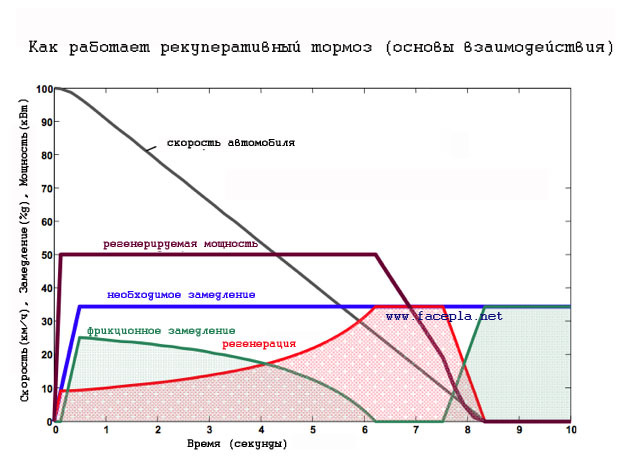
Diagrams characterizing one of the modes of recuperation energy received in conjunction with a mechanical (friction) brake for a hybrid. The graph is taken from here .
It was noted that the stator of the motor can rotate during braking, if you give it the opportunity to do this, for example, put it in a bearing. The idea came to use the energy of such a rotating stator, i.e. here the rotor stopped due to mechanical braking will act as a stator, and a rotating stator will act as a rotor. A conditional image of this process is shown in the video, first the conditional rotor rotates, with a load on the shaft, then the conditional stator:
Naturally, to achieve the right moment on the shaft, its stator must be static. The stator rotation speed, with mechanical braking, will depend on the achieved moment on the shaft, the moment of inertia of the stator itself and the friction moment, on which the stator rotation depends. Those. the formula that describes the rotation of the stator should look like this:

 - angular (rotational) acceleration of the stator
 - angular (rotational) acceleration of the shaft before braking
 - moment of inertia of the stator
 - moment of inertia of the shaft
 - moment of friction acting on the rotation of the stator
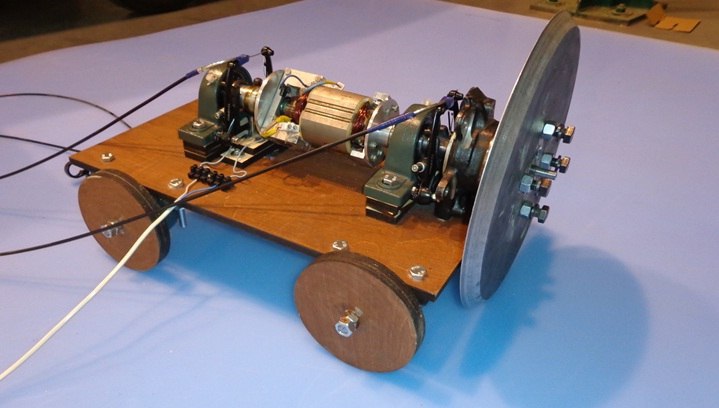
Let us describe the experiment in more detail. The experimental setup was made:
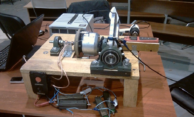
It consisted of a portable platform on which an electric motor, brakes and measuring instruments were mounted. For an electric motor with permanent magnet excitation, with a power of 250 W, an adapter made of PCB was inserted into which a steel pin was screwed, the pin was inserted into the housing bearing, the adapter allowed the stator to rotate in the bearing when the motor shaft was braking, and also, by choice, for subsequent comparisons, Leave the stator static with the help of an inserted stop.
An aluminum disk with a diameter of 300 mm and a thickness of 10 mm was attached to the shaft of the electric motor, and, in turn, a manual mechanical brake was installed.
During mechanical braking, the recovery energy was supplied to a PCS 250 two-channel USB oscilloscope, the oscilloscope gave the value of this energy to the computer.
To measure energy, several resistors with a resistance of 1 Ohm, a power of 20 and 100 W connected in parallel with each other, which were used to calculate the current in the circuit, were connected from the oscilloscope to the second channel of the oscilloscope.
Recording energy recovery data during mechanical braking of the shaft was carried out in two modes, with a non-rotating stator and a rotating stator. For these two modes, the same maximum interval of the disk rotation frequency was chosen at which the experimental data were recorded, this interval ranged from 500 to 600 rpm. In total, 12 measurements were made for each mode.
As a result, 8 measurements for each mode were taken for processing. So that the arithmetic mean value of the maximum shaft speed before braking, for the two modes were approximately the same.
By calculating the standard deviation (for each mode separately), the results of the recovered energy obtained were eliminated, which did not fall within the confidence interval.
For the rotating stator, the arithmetic mean was 558.5 (rpm), for the static stator 559.1 (rpm).
The arithmetic mean value of the recovered energy during mechanical braking for the rotating stator was 5.3 J, for the static stator 2.04 J. The

number of tests and the number of energy received for the two modes
It is worth paying attention to the polarity of the recovered energy during mechanical braking; the voltage in the new electric motor changed reverse polarity:
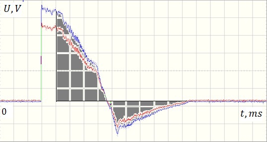
And in a design with a static stator, the voltage did not change its polarity:

The mechanical braking region is shaded in the figures. One cell in the waveform for t (time) is 200 ms, for U (voltage) it is 0.2 V.
To use the energy of reverse polarity, you can use the polarity switch for these purposes.
It is also worth noting that recovery with a rotating stator in a mode without mechanical braking will be shorter, therefore, the time to “turn on” the stator rotation before mechanical braking should be as minimal as possible, but sufficient so that the rotation energy from the rotor passes to the stator. Judging from the oscillograms, a time of about 100 ms was sufficient, and no significant losses are visible in this period of time, it is probably possible to further reduce the time to a mechanical brake. There were ideas to make a second static stator above the rotating stator in order to reduce losses during non-mechanical braking, but this will complicate the design of the electric motor.
Prior to this development, there was a design with a sequential excitation electric motor, in which the stator also carried out rotations during mechanical braking of the shaft.

Conclusion: In the experimental design of the engine with mechanical braking of the shaft with a rotating stator, 2.5 times more recovery energy is obtained than with a static stator, which clearly illustrates the possibility of increasing the energy saving of electric motors in mechanical braking modes. The amount of energy recuperation here will be greater than the moment of rotation of the shaft before braking and the less the friction moment of the rotating stator, the also the moment of inertia permissible for rotation of the stator, and the smaller the moment of rotation of the shaft and the greater the friction moment of the rotating stator, etc. the energy of recovery will be less, i.e. in spite of the effect obtained, one should ask about the payback and reliability of structural changes for a device in which an electric motor with such an effect can be used.
Project management: Yulian Baryshnikov (design, assembly, experiment, part production, article writing, idea) - iulianbaryshnikov@yandex.ru Project
assistance: Vitaly Azarov (design, assembly, experiment), Anton Alyoshkin (design, assembly, parts manufacturing) ), M.V. Yakovitskaya (edition), Alexander Troitsky (conducting the experiment), Nikolay Eremin (software for the measuring device), Alena Chumak (design), Fablab Polytech St. Petersburg (manufacturing of parts, measuring instrument, experiment).
It is known that an electric motor can generate electricity during braking. Such braking is widely used in electric cars, trams, trolleybuses, electric trains, trains, as well as in centrifuges and in hoisting-and-transport equipment (cranes, hoists, elevators), etc., but the amount of electricity generated in the mechanical brake modes is relatively small .
Diagrams characterizing one of the modes of recuperation energy received in conjunction with a mechanical (friction) brake for a hybrid. The graph is taken from here .
It was noted that the stator of the motor can rotate during braking, if you give it the opportunity to do this, for example, put it in a bearing. The idea came to use the energy of such a rotating stator, i.e. here the rotor stopped due to mechanical braking will act as a stator, and a rotating stator will act as a rotor. A conditional image of this process is shown in the video, first the conditional rotor rotates, with a load on the shaft, then the conditional stator:
Naturally, to achieve the right moment on the shaft, its stator must be static. The stator rotation speed, with mechanical braking, will depend on the achieved moment on the shaft, the moment of inertia of the stator itself and the friction moment, on which the stator rotation depends. Those. the formula that describes the rotation of the stator should look like this:
- angular (rotational) acceleration of the stator - angular (rotational) acceleration of the shaft before braking - moment of inertia of the stator - moment of inertia of the shaft - moment of friction acting on the rotation of the stator Let us describe the experiment in more detail. The experimental setup was made:
It consisted of a portable platform on which an electric motor, brakes and measuring instruments were mounted. For an electric motor with permanent magnet excitation, with a power of 250 W, an adapter made of PCB was inserted into which a steel pin was screwed, the pin was inserted into the housing bearing, the adapter allowed the stator to rotate in the bearing when the motor shaft was braking, and also, by choice, for subsequent comparisons, Leave the stator static with the help of an inserted stop.
An aluminum disk with a diameter of 300 mm and a thickness of 10 mm was attached to the shaft of the electric motor, and, in turn, a manual mechanical brake was installed.
During mechanical braking, the recovery energy was supplied to a PCS 250 two-channel USB oscilloscope, the oscilloscope gave the value of this energy to the computer.
To measure energy, several resistors with a resistance of 1 Ohm, a power of 20 and 100 W connected in parallel with each other, which were used to calculate the current in the circuit, were connected from the oscilloscope to the second channel of the oscilloscope.
Recording energy recovery data during mechanical braking of the shaft was carried out in two modes, with a non-rotating stator and a rotating stator. For these two modes, the same maximum interval of the disk rotation frequency was chosen at which the experimental data were recorded, this interval ranged from 500 to 600 rpm. In total, 12 measurements were made for each mode.
As a result, 8 measurements for each mode were taken for processing. So that the arithmetic mean value of the maximum shaft speed before braking, for the two modes were approximately the same.
By calculating the standard deviation (for each mode separately), the results of the recovered energy obtained were eliminated, which did not fall within the confidence interval.
For the rotating stator, the arithmetic mean was 558.5 (rpm), for the static stator 559.1 (rpm).
The arithmetic mean value of the recovered energy during mechanical braking for the rotating stator was 5.3 J, for the static stator 2.04 J. The
number of tests and the number of energy received for the two modes
It is worth paying attention to the polarity of the recovered energy during mechanical braking; the voltage in the new electric motor changed reverse polarity:
And in a design with a static stator, the voltage did not change its polarity:
The mechanical braking region is shaded in the figures. One cell in the waveform for t (time) is 200 ms, for U (voltage) it is 0.2 V.
To use the energy of reverse polarity, you can use the polarity switch for these purposes.
It is also worth noting that recovery with a rotating stator in a mode without mechanical braking will be shorter, therefore, the time to “turn on” the stator rotation before mechanical braking should be as minimal as possible, but sufficient so that the rotation energy from the rotor passes to the stator. Judging from the oscillograms, a time of about 100 ms was sufficient, and no significant losses are visible in this period of time, it is probably possible to further reduce the time to a mechanical brake. There were ideas to make a second static stator above the rotating stator in order to reduce losses during non-mechanical braking, but this will complicate the design of the electric motor.
Prior to this development, there was a design with a sequential excitation electric motor, in which the stator also carried out rotations during mechanical braking of the shaft.
Conclusion: In the experimental design of the engine with mechanical braking of the shaft with a rotating stator, 2.5 times more recovery energy is obtained than with a static stator, which clearly illustrates the possibility of increasing the energy saving of electric motors in mechanical braking modes. The amount of energy recuperation here will be greater than the moment of rotation of the shaft before braking and the less the friction moment of the rotating stator, the also the moment of inertia permissible for rotation of the stator, and the smaller the moment of rotation of the shaft and the greater the friction moment of the rotating stator, etc. the energy of recovery will be less, i.e. in spite of the effect obtained, one should ask about the payback and reliability of structural changes for a device in which an electric motor with such an effect can be used.
Project management: Yulian Baryshnikov (design, assembly, experiment, part production, article writing, idea) - iulianbaryshnikov@yandex.ru Project
assistance: Vitaly Azarov (design, assembly, experiment), Anton Alyoshkin (design, assembly, parts manufacturing) ), M.V. Yakovitskaya (edition), Alexander Troitsky (conducting the experiment), Nikolay Eremin (software for the measuring device), Alena Chumak (design), Fablab Polytech St. Petersburg (manufacturing of parts, measuring instrument, experiment).